EP0096831A1 - Werkzeugmaschinen für zweiflächige Fräsarbeiten - Google Patents
Werkzeugmaschinen für zweiflächige Fräsarbeiten Download PDFInfo
- Publication number
- EP0096831A1 EP0096831A1 EP19830105588 EP83105588A EP0096831A1 EP 0096831 A1 EP0096831 A1 EP 0096831A1 EP 19830105588 EP19830105588 EP 19830105588 EP 83105588 A EP83105588 A EP 83105588A EP 0096831 A1 EP0096831 A1 EP 0096831A1
- Authority
- EP
- European Patent Office
- Prior art keywords
- arbor
- cutters
- spindle
- machine tool
- power station
- Prior art date
- Legal status (The legal status is an assumption and is not a legal conclusion. Google has not performed a legal analysis and makes no representation as to the accuracy of the status listed.)
- Ceased
Links
- 238000003801 milling Methods 0.000 title claims abstract description 56
- 230000008878 coupling Effects 0.000 claims description 5
- 238000010168 coupling process Methods 0.000 claims description 5
- 238000005859 coupling reaction Methods 0.000 claims description 5
- 230000002452 interceptive effect Effects 0.000 claims 1
- 238000000926 separation method Methods 0.000 abstract description 2
- 230000000295 complement effect Effects 0.000 description 4
- 238000003754 machining Methods 0.000 description 4
- 230000005284 excitation Effects 0.000 description 2
- 238000004519 manufacturing process Methods 0.000 description 2
- 238000005520 cutting process Methods 0.000 description 1
- 230000003247 decreasing effect Effects 0.000 description 1
- 238000006073 displacement reaction Methods 0.000 description 1
- 230000037431 insertion Effects 0.000 description 1
- 238000003780 insertion Methods 0.000 description 1
- 239000002184 metal Substances 0.000 description 1
- 238000005555 metalworking Methods 0.000 description 1
- 125000006850 spacer group Chemical group 0.000 description 1
Images

Classifications
-
- B—PERFORMING OPERATIONS; TRANSPORTING
- B23—MACHINE TOOLS; METAL-WORKING NOT OTHERWISE PROVIDED FOR
- B23C—MILLING
- B23C1/00—Milling machines not designed for particular work or special operations
-
- B—PERFORMING OPERATIONS; TRANSPORTING
- B23—MACHINE TOOLS; METAL-WORKING NOT OTHERWISE PROVIDED FOR
- B23Q—DETAILS, COMPONENTS, OR ACCESSORIES FOR MACHINE TOOLS, e.g. ARRANGEMENTS FOR COPYING OR CONTROLLING; MACHINE TOOLS IN GENERAL CHARACTERISED BY THE CONSTRUCTION OF PARTICULAR DETAILS OR COMPONENTS; COMBINATIONS OR ASSOCIATIONS OF METAL-WORKING MACHINES, NOT DIRECTED TO A PARTICULAR RESULT
- B23Q17/00—Arrangements for observing, indicating or measuring on machine tools
- B23Q17/22—Arrangements for observing, indicating or measuring on machine tools for indicating or measuring existing or desired position of tool or work
- B23Q17/2283—Arrangements for observing, indicating or measuring on machine tools for indicating or measuring existing or desired position of tool or work for adjusting the distance between coaxially rotating tools
-
- B—PERFORMING OPERATIONS; TRANSPORTING
- B23—MACHINE TOOLS; METAL-WORKING NOT OTHERWISE PROVIDED FOR
- B23Q—DETAILS, COMPONENTS, OR ACCESSORIES FOR MACHINE TOOLS, e.g. ARRANGEMENTS FOR COPYING OR CONTROLLING; MACHINE TOOLS IN GENERAL CHARACTERISED BY THE CONSTRUCTION OF PARTICULAR DETAILS OR COMPONENTS; COMBINATIONS OR ASSOCIATIONS OF METAL-WORKING MACHINES, NOT DIRECTED TO A PARTICULAR RESULT
- B23Q1/00—Members which are comprised in the general build-up of a form of machine, particularly relatively large fixed members
- B23Q1/70—Stationary or movable members for carrying working-spindles for attachment of tools or work
-
- Y—GENERAL TAGGING OF NEW TECHNOLOGICAL DEVELOPMENTS; GENERAL TAGGING OF CROSS-SECTIONAL TECHNOLOGIES SPANNING OVER SEVERAL SECTIONS OF THE IPC; TECHNICAL SUBJECTS COVERED BY FORMER USPC CROSS-REFERENCE ART COLLECTIONS [XRACs] AND DIGESTS
- Y10—TECHNICAL SUBJECTS COVERED BY FORMER USPC
- Y10T—TECHNICAL SUBJECTS COVERED BY FORMER US CLASSIFICATION
- Y10T409/00—Gear cutting, milling, or planing
- Y10T409/30—Milling
- Y10T409/30084—Milling with regulation of operation by templet, card, or other replaceable information supply
- Y10T409/300896—Milling with regulation of operation by templet, card, or other replaceable information supply with sensing of numerical information and regulation without mechanical connection between sensing means and regulated means [i.e., numerical control]
-
- Y—GENERAL TAGGING OF NEW TECHNOLOGICAL DEVELOPMENTS; GENERAL TAGGING OF CROSS-SECTIONAL TECHNOLOGIES SPANNING OVER SEVERAL SECTIONS OF THE IPC; TECHNICAL SUBJECTS COVERED BY FORMER USPC CROSS-REFERENCE ART COLLECTIONS [XRACs] AND DIGESTS
- Y10—TECHNICAL SUBJECTS COVERED BY FORMER USPC
- Y10T—TECHNICAL SUBJECTS COVERED BY FORMER US CLASSIFICATION
- Y10T409/00—Gear cutting, milling, or planing
- Y10T409/30—Milling
- Y10T409/30448—Milling with detachable or auxiliary cutter support to convert cutting action
-
- Y—GENERAL TAGGING OF NEW TECHNOLOGICAL DEVELOPMENTS; GENERAL TAGGING OF CROSS-SECTIONAL TECHNOLOGIES SPANNING OVER SEVERAL SECTIONS OF THE IPC; TECHNICAL SUBJECTS COVERED BY FORMER USPC CROSS-REFERENCE ART COLLECTIONS [XRACs] AND DIGESTS
- Y10—TECHNICAL SUBJECTS COVERED BY FORMER USPC
- Y10T—TECHNICAL SUBJECTS COVERED BY FORMER US CLASSIFICATION
- Y10T409/00—Gear cutting, milling, or planing
- Y10T409/30—Milling
- Y10T409/30784—Milling including means to adustably position cutter
- Y10T409/307952—Linear adjustment
- Y10T409/308344—Plural cutters
-
- Y—GENERAL TAGGING OF NEW TECHNOLOGICAL DEVELOPMENTS; GENERAL TAGGING OF CROSS-SECTIONAL TECHNOLOGIES SPANNING OVER SEVERAL SECTIONS OF THE IPC; TECHNICAL SUBJECTS COVERED BY FORMER USPC CROSS-REFERENCE ART COLLECTIONS [XRACs] AND DIGESTS
- Y10—TECHNICAL SUBJECTS COVERED BY FORMER USPC
- Y10T—TECHNICAL SUBJECTS COVERED BY FORMER US CLASSIFICATION
- Y10T409/00—Gear cutting, milling, or planing
- Y10T409/30—Milling
- Y10T409/30784—Milling including means to adustably position cutter
- Y10T409/308568—Plural cutters
-
- Y—GENERAL TAGGING OF NEW TECHNOLOGICAL DEVELOPMENTS; GENERAL TAGGING OF CROSS-SECTIONAL TECHNOLOGIES SPANNING OVER SEVERAL SECTIONS OF THE IPC; TECHNICAL SUBJECTS COVERED BY FORMER USPC CROSS-REFERENCE ART COLLECTIONS [XRACs] AND DIGESTS
- Y10—TECHNICAL SUBJECTS COVERED BY FORMER USPC
- Y10T—TECHNICAL SUBJECTS COVERED BY FORMER US CLASSIFICATION
- Y10T409/00—Gear cutting, milling, or planing
- Y10T409/30—Milling
- Y10T409/30952—Milling with cutter holder
-
- Y—GENERAL TAGGING OF NEW TECHNOLOGICAL DEVELOPMENTS; GENERAL TAGGING OF CROSS-SECTIONAL TECHNOLOGIES SPANNING OVER SEVERAL SECTIONS OF THE IPC; TECHNICAL SUBJECTS COVERED BY FORMER USPC CROSS-REFERENCE ART COLLECTIONS [XRACs] AND DIGESTS
- Y10—TECHNICAL SUBJECTS COVERED BY FORMER USPC
- Y10T—TECHNICAL SUBJECTS COVERED BY FORMER US CLASSIFICATION
- Y10T83/00—Cutting
- Y10T83/768—Rotatable disc tool pair or tool and carrier
- Y10T83/7809—Tool pair comprises rotatable tools
- Y10T83/7847—Tool element axially shiftable
Definitions
- This invention relates generally to milling machine tools and more specifically, this invention relates to a milling machine having a numerically controlled adjustable arbor to enable automatic adjustment of the width between arbor milling cutters car - ried on the arbor thereby facilitating random workpiece machining.
- Milling machines which are generally employed to carry out milling operations have a rotary driven spindle for rotatably driving the milling cutter and a movable table for supporting the workpiece and for moving the workpiece into operative engagement with the milling cutter.
- Small and moderate size milling cutters are usually carried on a toolholder which is inserted directly into the milling machine spindle so as to be rotatably driven thereby.
- securing the milling cutter to a toolholder for insertion into the spindle becomes impractical.
- the large milling cutter is coaxially carried on an arbor which is secured at one end to the machine tool spindle and is rotatably supported at its other end on the machine tool by one or more arbor supports in coaxial alignment with the spindle.
- the arbor can carry more than one large milling cutter at a time.
- the present invention discloses a machine tool having a numerically controlled adjustable arbor set up which allows for automatic control of the width of arbor milling cutters responsive to N/C commands, thereby eliminating the need for operator intervention when machining random workpieces.
- the present invention provides a machine tool having a power driven rotary spindle for rotating cutters in work operations, an arbor coupled to be rotated by said spindle, characterized by a pair of cutters keyed to said arbor for rotation therewith, said cutters being supported on said arbor in spaced relationship for performing straddle milling operations, power means connected to adjust the spacing of said cutters to vary the cut; and a control connected to regulate the operation of said power means for controlling the adjustment of the spacing of said cutters.
- the arbor is adjustable to vary the spacing between the cutters responsive to numerical control commands.
- a power station is carried on the machine tool frame and has a rotatably driven spindle which is carried in a quill journaled in the power station for reciprocal movement out from and into the power station along the axis of the arbor supports.
- the power station is provided with a pair of servo controlled motors for driving the spindle and for axially reciprocating the quill, respectively responsive to numerical control commands.
- the arbor is coupled to the spindle and extends through the first arbor support so that its opposite end is journaled into the second arbor support for co-joint rotation with the spindle.
- the arbor is advantageously comprised of a pair of cylindrical members in sleeved engagement with each other so as to be axially movable to and from each other while rotating co-jointly with each other.
- Each of the arbor members is adapted to carry an arbor milling cutter thereon in parallel spaced apart coaxial alignment with the milling cutter on the other of arbor members.
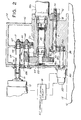
- a machine tool 10 having a numerically controlled adjustable arbor set up to facilitate random workpiece machining comprises a frame 12 which, in the presently preferred embodiment, is slidably mounted on a platform 14 for movement on the platform along a set of platform ways 16.
- the frame is slidably secured to the platform by roller gibs 18 which are attached to frame 12 by bolts 20.
- Means typically taking the form of a servo-driven ball screw and a ball nut are provided for precisely displacing frame 12 along platform 14 in response to numerical control commands.
- Frame 12 carries a power station 22 thereon, the power station being affixed to the frame at one end thereof.
- power station 22 has a rotary driven spindle 24 carried in a quill 26 which is axially reciprocal out from and into the power station along the axis of spindle rotation in response to numerical control commands.
- An arbor 28 for carrying large milling cutters thereon is secured at one end thereof to spindle 24 and is journaled at its opposite end into a fixed arbor support 30 which is carried on frame 12 opposite to power station 22 so to be in axial alignment with spindle 24.
- arbor 28 is journaled through an intermediate arbor support 32 which is affixed to frame 12 medially between outer arbor support 30 and power station 22.
- arbor 28 is advantageously bifurcated and comprises a pair of arbor members 28a and 28b which are in sleeved engagement with each other so as to be axially movable to and from each other while undergoing co-joint rotation.
- arbor member 28a which is secured at one end thereof to spindle 24, has a bore 34 in the end thereof distal from spindle 24, which bore is dimensioned to receive the reduced diameter end 36 of arbor member 28b whose opposite end is journaled in arbor support 30.
- the reduced diameter end 36 of arbor member 28b has a radially embedded, axially extending key 38 which is in engagement with a complementary keyway 40 inscribed in bore 34 in the end of arbor member 28a.
- the sliding engagement of key 38 of arbor member 28b within keyway 40 of arbor member 28a enables arbor member 28a to be reciprocated relative to arbor member 28b when quill 26 is reciprocated out from and into power station 22 in response to numerical control commands while both the arbor members are rotatably driven by spindle 24.
- Each of arbor members 28a and 28b is dimensioned to carry at least one conventional arbor milling cutter 42, the arbor milling cutter on each arbor member bearing against a flange 44 integrated to the arbor member adjacent to the end of the arbor member.
- the sleeved engagement of arbor member 28a with arbor member 28b facilitates axial movement of arbor milling cutter 42 on arbor member 28a to and from arbor milling cutter 42 on arbor 28b as the milling cutters are rotated simultaneously by the arbor members.
- the spacing between cutters 42 can be varied automatically in contrast to the fixed arbor milling cutter spacing of prior art of arbor arrangements.
- arbor milling cutter 42 on arbor member 28a is positioned at a predetermined minimum distance from arbor milling cutter 42 on arbor member 28b as is illustrated in solid lines in Figure 1.
- arbor milling cutter 42 on arbor member 28a is axially displaced apart from cutter 42 on arbor member 28b.
- power station 22 is comprised of a housing 46 which is secured to frame 12 by fasteners (not shown). Housing 46 has an opening in the forward (rightward) end thereof for receiving quill 26 within which spindle 24 is journaled by bearings 48a and 48b, each bearing being carried on the spindle at separate one of the spindle ends.
- the rearward (leftward) end of spindle 24 is tapered and extends beyond quill 26 for carrying a gear 50 which has a complementary tapered bore therethrough.
- a nut 52 is threaded about the end of the spindle to bear against gear 50 to secure the gear on the spindle.
- a key 54 is axially embedded in the rearward spindle end to engage a complementary keyway (not shown) in the bore of gear 50 to maintain driving engagement between the spindle and the gear.
- the teeth on gear 50 meshingly engage the teeth on a complimentary-dimensioned drive pinion 56 which is journaled into housing 46 by bearings 58a and 58b so as to be parallel to spindle 24 and quill 26.
- the forward end of drive pinion 56 carries a spur gear 60 which is urged against a shoulder on the drive pinion by a nut 62 which is threaded about the forward end of the drive pinion.
- Spur gear 60 is dimensioned for meshing engagement with a spur gear 64 which is carried on the forward end of a drive shaft 68 that is journaled in housing 46 by bearings 70c and 70b so as to be parallel to quill 26 and drive pinion 56.
- a nut 71 is threaded onto the forward end of shaft 68 to urge gear 64 against a shoulder on the shaft to keep the gear secured to the shaft.
- Drive shaft 68 extends rearwardly through an opening in the rearward end of housing 46 for coupling the shaft of a spindle drive motor 72 via a universal coupling 74.
- Spindle drive motor 72 which is supported from frame 12 by brackets (not shown), so as to be adjacent to housing 46, is energized from a numerical control (N/C) circuit 78 such as are well known in the art, in response to N/C commands, which are supplied to the N/C control circuit from a tape reader or the like (not shown).
- N/C numerical control
- N/C control circuit 78 in addition to controlling the excitation of spindle drive motor 72 in accordance with N/C commands to precisely control spindle rotation, also controls the excitation of a motor 80, which as will be seen hereinafter, is operative to reciprocate the quill 26 out from and into housing 46 in accordance with the difference between the desired quill position, as represented by N/C commands entered to N/C control circuit 78, and the actual quill position as represented by the output signal of a feedback transducer 82 which is attached to motor 80 for supplying the N/C control circuit with an electrical signal indicative of the motor shaft position.
- a motor 80 which as will be seen hereinafter, is operative to reciprocate the quill 26 out from and into housing 46 in accordance with the difference between the desired quill position, as represented by N/C commands entered to N/C control circuit 78, and the actual quill position as represented by the output signal of a feedback transducer 82 which is attached to motor 80 for supplying the N/C control circuit with an electrical signal indicative of the
- motor 80 secured to the rearward end of housing 46 so that its shaft 84 extends through an opening in the rearward housing end.
- a pair of bearings 86a and 86b are carried on the rearward and forward motor shaft ends, respectively and journal the shaft to the housing so that the shaft is parallel to the axis of quill 26 and spindle 24.
- a gear 88 is carried on the forward end of motor shaft 84 and is dimensionsed for meshing engagement with a gear 90 carried on the rearward end of a shaft 91 which is journaled in housing 46 by bearings 92a and 92b so as to be parallel to spindle 24, quill 26 and shaft 84.
- the forward end 94 of shaft 91 is threaded for meshingly engaging complementary threads on the bore of a nut 96 which is pressed into the bore of the radially extending portion of a flange-like member 98 which circumscribes the forward end of the quill.
- the co-action of the threads on shaft 91 with the threads of nut 96 causes nut 96, flange 98 and hence quill 26 and spindle 24 to be urged rearwardly into housing 46 as shaft 91 is threaded into nut 96..
- the nut, the flange and hence the quill and the spindle are urged forwardly from housing 46.
- the axial reciprocation of quill 26 out from and into housing 46 can be varied accordingly.
- N/C control circuit 78 The rotation of motor shaft 84 and shaft 91, which as just indicated causes the reciprocation of quill 26 and hence the displacement of arbor milling cutters 42, on arbor 28a from arbor milling cutter 42 on arbor member 28, is controlled by N/C control circuit 78 in accordance with the difference between the desired motor shaft position, as determined by the N/C commands received by N/C control system 78, and the actual motor shaft position as represented by the output signal of feedback transducer 82, which output signal corresponds to the actual quill position. In this way the spacing between arbor milling cutters can be controlled automatically by simply entering the appropriate N/C command to the N/C control circuit. Typically such N/C commands would be stored on tape and supplied to N/C control circuit 78 automatically during machine tool operation.
- the foregoing discloses a machine tool having a numerically controlled adjustable arbor set up for automatically varying the separation between arbor milling cutters so as to enable random workpiece machining without operator intervention.
Landscapes
- Engineering & Computer Science (AREA)
- Mechanical Engineering (AREA)
- Milling Processes (AREA)
- Drilling And Boring (AREA)
Applications Claiming Priority (2)
| Application Number | Priority Date | Filing Date | Title |
|---|---|---|---|
| US385906 | 1982-06-07 | ||
| US06/385,906 US4536111A (en) | 1982-06-07 | 1982-06-07 | Machine tool having numerically controlled adjustable arbor set up for straddle milling |
Publications (1)
| Publication Number | Publication Date |
|---|---|
| EP0096831A1 true EP0096831A1 (de) | 1983-12-28 |
Family
ID=23523367
Family Applications (1)
| Application Number | Title | Priority Date | Filing Date |
|---|---|---|---|
| EP19830105588 Ceased EP0096831A1 (de) | 1982-06-07 | 1983-06-07 | Werkzeugmaschinen für zweiflächige Fräsarbeiten |
Country Status (5)
| Country | Link |
|---|---|
| US (1) | US4536111A (de) |
| EP (1) | EP0096831A1 (de) |
| JP (1) | JPS591110A (de) |
| KR (1) | KR840005368A (de) |
| IL (1) | IL68763A0 (de) |
Cited By (1)
| Publication number | Priority date | Publication date | Assignee | Title |
|---|---|---|---|---|
| ES2068057A2 (es) * | 1991-10-17 | 1995-04-01 | Const Aeronauticas Sa | Dispositivo de redoblonado. |
Families Citing this family (3)
| Publication number | Priority date | Publication date | Assignee | Title |
|---|---|---|---|---|
| US4684300A (en) * | 1986-04-30 | 1987-08-04 | Ridgetown Ltd. | Attachment for a vertical mill |
| DE3804502A1 (de) * | 1988-02-13 | 1989-08-31 | Heller Geb Gmbh Maschf | Vorrichtung zum bearbeiten von rotationssymmetrischen werkstueckflaechen |
| DE102006005253A1 (de) * | 2006-02-02 | 2007-08-09 | Otto Martin Maschinenbau Gmbh & Co. Kg | Einstellverfahren für Vorritzsägeblätter |
Citations (2)
| Publication number | Priority date | Publication date | Assignee | Title |
|---|---|---|---|---|
| DE2243681A1 (de) * | 1972-04-14 | 1973-10-18 | Illinois Tool Works | Verfahren und vorrichtung zur herstellung von dichtungen aufnehmenden, langgestreckten nuten in der seitenflaeche eines werkstueckes, insbesondere dem rotor einer rotorbrennkraftmaschine |
| DE2436810A1 (de) * | 1974-07-31 | 1976-02-19 | Frantisek Flekac | Vorrichtung zur feineinstellung der abstaende zwischen den auf einem fraesdorn angeordneten fraesern |
Family Cites Families (8)
| Publication number | Priority date | Publication date | Assignee | Title |
|---|---|---|---|---|
| US1658267A (en) * | 1923-11-01 | 1928-02-07 | Kearney & Trecker Corp | Attachment for machine tools having a plurality of overarms |
| US2699338A (en) * | 1949-06-27 | 1955-01-11 | Pabst Brewing Co | Mandrel for label coding machines |
| DE1752832C3 (de) * | 1967-07-29 | 1979-08-09 | Ing. C. Olivetti & C., S.P.A., Ivrea, Turin (Italien) | Vorrichtung zur lösbaren Verbindung eines Werkzeugs mit der Spindel einer Werkzeugmaschine |
| US3630244A (en) * | 1970-03-27 | 1971-12-28 | Industrial Woodworking Mach | Saw apparatus with laterally adjustable saws |
| US3899955A (en) * | 1971-04-20 | 1975-08-19 | Selch James I | Machine tool construction |
| US3750513A (en) * | 1972-05-15 | 1973-08-07 | Industrial Woodworking Mach | Telescoping arbor assembly |
| US4266893A (en) * | 1978-10-16 | 1981-05-12 | Forschungsinstitut Fur Holztechnologie | Positioner for rotary tool |
| LU82096A1 (fr) * | 1980-01-21 | 1981-09-10 | Know How Ets Ind | Perfectionnements aux machines-outils du type centre d'usinage |
-
1982
- 1982-06-07 US US06/385,906 patent/US4536111A/en not_active Expired - Fee Related
-
1983
- 1983-05-23 IL IL68763A patent/IL68763A0/xx unknown
- 1983-06-06 JP JP58099635A patent/JPS591110A/ja active Pending
- 1983-06-07 EP EP19830105588 patent/EP0096831A1/de not_active Ceased
- 1983-06-07 KR KR1019830002519A patent/KR840005368A/ko not_active Abandoned
Patent Citations (2)
| Publication number | Priority date | Publication date | Assignee | Title |
|---|---|---|---|---|
| DE2243681A1 (de) * | 1972-04-14 | 1973-10-18 | Illinois Tool Works | Verfahren und vorrichtung zur herstellung von dichtungen aufnehmenden, langgestreckten nuten in der seitenflaeche eines werkstueckes, insbesondere dem rotor einer rotorbrennkraftmaschine |
| DE2436810A1 (de) * | 1974-07-31 | 1976-02-19 | Frantisek Flekac | Vorrichtung zur feineinstellung der abstaende zwischen den auf einem fraesdorn angeordneten fraesern |
Cited By (1)
| Publication number | Priority date | Publication date | Assignee | Title |
|---|---|---|---|---|
| ES2068057A2 (es) * | 1991-10-17 | 1995-04-01 | Const Aeronauticas Sa | Dispositivo de redoblonado. |
Also Published As
| Publication number | Publication date |
|---|---|
| IL68763A0 (en) | 1983-09-30 |
| US4536111A (en) | 1985-08-20 |
| JPS591110A (ja) | 1984-01-06 |
| KR840005368A (ko) | 1984-11-12 |
Similar Documents
| Publication | Publication Date | Title |
|---|---|---|
| JPH11165211A (ja) | 内面加工機 | |
| DE19546197C1 (de) | Verfahren und Vorrichtung zum Drehfräsen | |
| US4536111A (en) | Machine tool having numerically controlled adjustable arbor set up for straddle milling | |
| US3637318A (en) | Drilling apparatus | |
| JPH10286720A (ja) | スクリュロータのスクリュ部加工方法 | |
| US5435360A (en) | Method for positioning a machine element having a reference point relative to a reference point provided at an abutment | |
| GB2231290A (en) | Milling cutter grinding machine | |
| CN213828228U (zh) | 一种全自动在线锥孔研磨机 | |
| CN217413414U (zh) | 一种用于筒形物料的端面整形设备 | |
| JPH05162015A (ja) | 対向砥石台を備えたねじ研削盤 | |
| CN217371847U (zh) | 一种用于筒形物料的端面抛光设备 | |
| JPH088054Y2 (ja) | 旋削加工機の切削剤供給装置 | |
| CN215200708U (zh) | 一种金属件cnc加工用锁刀座 | |
| CN220659885U (zh) | 一种卧式单面双工位钻孔攻丝组合机床 | |
| JPH071231A (ja) | 面取り兼シェービング装置 | |
| KR100393635B1 (ko) | 범용 공작기계의 씨엔씨 장치 | |
| KR200216668Y1 (ko) | 범용 공작기계의 씨엔씨 장치 | |
| CN2071549U (zh) | 内孔割槽自动进退装置 | |
| US4484499A (en) | Rear portion supporting mechanism in apparatus for machining elongated workpieces | |
| JPH1015712A (ja) | Atc式中ぐりマシニングセンタの加工穴径自動補正装置及びその方法 | |
| US2867154A (en) | Retracting mechanism | |
| JPS61159342A (ja) | ロ−ル加工装置 | |
| US2965008A (en) | Apparatus for machining cylindrical objects | |
| JP2700685B2 (ja) | 長手方向の位置決め装置 | |
| JPH04348841A (ja) | Nc工作機械 |
Legal Events
| Date | Code | Title | Description |
|---|---|---|---|
| PUAI | Public reference made under article 153(3) epc to a published international application that has entered the european phase |
Free format text: ORIGINAL CODE: 0009012 |
|
| AK | Designated contracting states |
Designated state(s): BE CH DE FR GB IT LI |
|
| 17P | Request for examination filed |
Effective date: 19840202 |
|
| STAA | Information on the status of an ep patent application or granted ep patent |
Free format text: STATUS: THE APPLICATION HAS BEEN REFUSED |
|
| 18R | Application refused |
Effective date: 19860715 |
|
| RIN1 | Information on inventor provided before grant (corrected) |
Inventor name: KIELMA, ERVIN J. |