EP0096832A2 - Dispositif de collage transversal pour bandes entraînées à haute vitesse - Google Patents
Dispositif de collage transversal pour bandes entraînées à haute vitesse Download PDFInfo
- Publication number
- EP0096832A2 EP0096832A2 EP83105590A EP83105590A EP0096832A2 EP 0096832 A2 EP0096832 A2 EP 0096832A2 EP 83105590 A EP83105590 A EP 83105590A EP 83105590 A EP83105590 A EP 83105590A EP 0096832 A2 EP0096832 A2 EP 0096832A2
- Authority
- EP
- European Patent Office
- Prior art keywords
- adhesive
- unit according
- application cylinder
- gluing unit
- cylinder
- Prior art date
- Legal status (The legal status is an assumption and is not a legal conclusion. Google has not performed a legal analysis and makes no representation as to the accuracy of the status listed.)
- Granted
Links
Images
Classifications
-
- B—PERFORMING OPERATIONS; TRANSPORTING
- B65—CONVEYING; PACKING; STORING; HANDLING THIN OR FILAMENTARY MATERIAL
- B65H—HANDLING THIN OR FILAMENTARY MATERIAL, e.g. SHEETS, WEBS, CABLES
- B65H45/00—Folding thin material
- B65H45/12—Folding articles or webs with application of pressure to define or form crease lines
- B65H45/30—Folding in combination with creasing, smoothing or application of adhesive
-
- B—PERFORMING OPERATIONS; TRANSPORTING
- B05—SPRAYING OR ATOMISING IN GENERAL; APPLYING FLUENT MATERIALS TO SURFACES, IN GENERAL
- B05C—APPARATUS FOR APPLYING FLUENT MATERIALS TO SURFACES, IN GENERAL
- B05C1/00—Apparatus in which liquid or other fluent material is applied to the surface of the work by contact with a member carrying the liquid or other fluent material, e.g. a porous member loaded with a liquid to be applied as a coating
- B05C1/04—Apparatus in which liquid or other fluent material is applied to the surface of the work by contact with a member carrying the liquid or other fluent material, e.g. a porous member loaded with a liquid to be applied as a coating for applying liquid or other fluent material to work of indefinite length
- B05C1/08—Apparatus in which liquid or other fluent material is applied to the surface of the work by contact with a member carrying the liquid or other fluent material, e.g. a porous member loaded with a liquid to be applied as a coating for applying liquid or other fluent material to work of indefinite length using a roller or other rotating member which contacts the work along a generating line
- B05C1/10—Apparatus in which liquid or other fluent material is applied to the surface of the work by contact with a member carrying the liquid or other fluent material, e.g. a porous member loaded with a liquid to be applied as a coating for applying liquid or other fluent material to work of indefinite length using a roller or other rotating member which contacts the work along a generating line the liquid or other fluent material being supplied from inside the roller
-
- Y—GENERAL TAGGING OF NEW TECHNOLOGICAL DEVELOPMENTS; GENERAL TAGGING OF CROSS-SECTIONAL TECHNOLOGIES SPANNING OVER SEVERAL SECTIONS OF THE IPC; TECHNICAL SUBJECTS COVERED BY FORMER USPC CROSS-REFERENCE ART COLLECTIONS [XRACs] AND DIGESTS
- Y10—TECHNICAL SUBJECTS COVERED BY FORMER USPC
- Y10T—TECHNICAL SUBJECTS COVERED BY FORMER US CLASSIFICATION
- Y10T156/00—Adhesive bonding and miscellaneous chemical manufacture
- Y10T156/17—Surface bonding means and/or assemblymeans with work feeding or handling means
- Y10T156/1702—For plural parts or plural areas of single part
- Y10T156/1712—Indefinite or running length work
- Y10T156/1722—Means applying fluent adhesive or adhesive activator material between layers
- Y10T156/1724—At spaced areas
-
- Y—GENERAL TAGGING OF NEW TECHNOLOGICAL DEVELOPMENTS; GENERAL TAGGING OF CROSS-SECTIONAL TECHNOLOGIES SPANNING OVER SEVERAL SECTIONS OF THE IPC; TECHNICAL SUBJECTS COVERED BY FORMER USPC CROSS-REFERENCE ART COLLECTIONS [XRACs] AND DIGESTS
- Y10—TECHNICAL SUBJECTS COVERED BY FORMER USPC
- Y10T—TECHNICAL SUBJECTS COVERED BY FORMER US CLASSIFICATION
- Y10T156/00—Adhesive bonding and miscellaneous chemical manufacture
- Y10T156/17—Surface bonding means and/or assemblymeans with work feeding or handling means
- Y10T156/1702—For plural parts or plural areas of single part
- Y10T156/1712—Indefinite or running length work
- Y10T156/1722—Means applying fluent adhesive or adhesive activator material between layers
- Y10T156/1727—Plural indefinite length or running length workpieces
-
- Y—GENERAL TAGGING OF NEW TECHNOLOGICAL DEVELOPMENTS; GENERAL TAGGING OF CROSS-SECTIONAL TECHNOLOGIES SPANNING OVER SEVERAL SECTIONS OF THE IPC; TECHNICAL SUBJECTS COVERED BY FORMER USPC CROSS-REFERENCE ART COLLECTIONS [XRACs] AND DIGESTS
- Y10—TECHNICAL SUBJECTS COVERED BY FORMER USPC
- Y10T—TECHNICAL SUBJECTS COVERED BY FORMER US CLASSIFICATION
- Y10T156/00—Adhesive bonding and miscellaneous chemical manufacture
- Y10T156/17—Surface bonding means and/or assemblymeans with work feeding or handling means
- Y10T156/1702—For plural parts or plural areas of single part
- Y10T156/1712—Indefinite or running length work
- Y10T156/1741—Progressive continuous bonding press [e.g., roll couples]
-
- Y—GENERAL TAGGING OF NEW TECHNOLOGICAL DEVELOPMENTS; GENERAL TAGGING OF CROSS-SECTIONAL TECHNOLOGIES SPANNING OVER SEVERAL SECTIONS OF THE IPC; TECHNICAL SUBJECTS COVERED BY FORMER USPC CROSS-REFERENCE ART COLLECTIONS [XRACs] AND DIGESTS
- Y10—TECHNICAL SUBJECTS COVERED BY FORMER USPC
- Y10T—TECHNICAL SUBJECTS COVERED BY FORMER US CLASSIFICATION
- Y10T156/00—Adhesive bonding and miscellaneous chemical manufacture
- Y10T156/17—Surface bonding means and/or assemblymeans with work feeding or handling means
- Y10T156/1798—Surface bonding means and/or assemblymeans with work feeding or handling means with liquid adhesive or adhesive activator applying means
Definitions
- the invention relates to a cross-gluing unit for very fast-moving webs, in particular for the bonding of several webs in rotary printing presses.
- very fast moving webs is understood to mean those with a continuously variable feed speed of several hundred meters / minute, for example 300 to 500 m / min.
- the invention is based on a known gluing device according to DE-PS 11 15 120, in which the adhesive is supplied from a storage container to the interior of a rotating application cylinder, on the circumference of which the web is tangent, and is applied to the web through outlet openings in the cylinder wall .
- the Queranleimung fast running paper webs is to the Ge - remained unresolved genwart, although this is a significant need in the printing industry exists. It is basically known to bind multi-page printed products in such a way that adhesive is applied to the individual web along the fold, which, after folding, causes adjacent pages to be glued in the fold area. In practice, this problem was solved by applying finally long adhesive strips that extend along the feed direction of the web (rationalization in the fatification of printed products, binder report No. 3/82, Industrie-Verlag). The application of adhesive strips of limited length requires complicated control of the application mechanism. Significant increases the machine speeds cannot be realized.
- cross-gluing For technical printing and folding reasons, it is not possible with certain printing machines, so-called half-width machines, to apply the adhesive application to the web as cross-gluing, whereby the term web is understood to mean not only an endless but also a finite one, for example a sheet .
- Such cross-gluing is required, however, that it must be applied precisely in the fold area with minimal adhesive expenditure and should have a sharp contour area in the form of a narrow line. This condition was not achievable. It is theoretically possible to connect a rotating applicator bar to a gluing unit, the box taking off the adhesive from a rotating roller immersed in a glue tank and transferring it to the web.
- the invention has for its object to develop a cross-gluing unit for very fast moving webs or blanks, which is capable of regardless of the changing speeds position and contour-accurate gluing at specified locations without the risk of the adhesive splashing away.
- the solution to this problem according to the invention is that the web wraps around a portion of the jacket of the application cylinder, the extent of which corresponds to the desired distance of the cross-gluing or a whole multiple of this distance, that the outlet openings extend along rows of jacket lines of the application cylinder in rows of bores A plurality are formed and that an adhesive feed channel extends to the inside of the individual outlet openings and is connected to a stationary axial adhesive connection of the application cylinder.
- the individual outlet opening is preferably designed as a bore (throttle nozzle) of such a diameter that the centrifugal force of the adhesive is only slightly greater than the opposing forces, even at high speeds of the application cylinder. It has proven to be advantageous if the outlet opening has a bore narrowing of about 2 to 4 mm in length with a diameter of about 0.3 mm behind an approximately 1 mm long bore outlet of approximately 0.8 mm in diameter.
- the invention initially avoided applying the adhesive from the cavity of a rotating cylinder. This is because the larger the filling quantity of the cylinder, the larger the surface of the adhesive mass and the more easily the adhesive tends to form skin. Instead, the cylinder has more of a carrying function in the subject matter of the invention. This is because the adhesive is fed through a tube (adhesive supply channel) which extends peripherally of the application cylinder along a surface line to the outlet openings in the form of bores or throttle nozzles.
- the adhesive application is based on the centrifugal force of the adhesive located in the outlet openings, which essentially counteracts the viscosity, the throttling effect (capillary effect) and the external pressure. It is now important to choose the cross-sections of the outlet openings so that the adhesive cannot spray out of the outlet openings even at high rotational speeds. Since the application cylinder is wrapped in a not inconsiderable part of its circumference by the web to be coated, the web has a covering effect in this area and prevents the adhesive from flowing out. There is only a kind of beading out of the adhesive from the outlet openings. Since the peripheral speed of the application cylinder is exactly the feed speed of the coating
- the application cylinder can, for example, be uncoupled from its drive and moved into a basic position in which the row of holes is accessible from the outside.
- the application cylinder When work is started again, the application cylinder must be returned to its correct working position and engaged with the drive.
- the outlet openings can be arranged individually, in groups or as a whole in an insert which is interchangeably connected to the application cylinder.
- the outlet openings can be covered on the inside in a controlled manner by a closure element.
- This closure element opens the access to the capillary openings as soon as the row of holes is covered by the web to be coated. Accordingly, the closure takes place in good time before the web leaves the jacket area of the application cylinder again.
- the closure element expediently passes through the adhesive feed channel and is driven in an oscillating or rotary manner.
- the closure element is designed as a strip-shaped sealing lip that can be adjusted against the inside of the outlet openings and is arranged radially at the top on a control shaft that passes through the adhesive feed channel with play and is rotatably mounted on the application cylinder.
- both the adhesive feed channel and the control shaft can be arranged in an insert, for example in a hollow strip, which fits into a suitable recess in the opening support cylinder can be used.
- the control shaft is provided with a gearwheel which rolls directly or indirectly on a stationary gearwheel arranged concentrically to the axis of the application cylinder.
- the control shaft makes the same rotation as the application cylinder, the control shaft also being able to rotate in the opposite direction to the application cylinder.
- the closure element is designed so that in the area where the row of holes is covered by the web to be coated, the outlet openings are connected to the feed channel and can release adhesive.
- the invention provides in a further embodiment that the application cylinder rotates with one Number or consumption-dependent metering arrangement for changing the filling quantity of the adhesive feed channel is provided or connected.
- a wide variety of options are available according to the invention for designing such metering arrangements. It is thus possible, for example, to design the metering arrangement from a valve which separates the adhesive feed channel from its connection to the adhesive connection and in particular is arranged in a radial connecting line.
- This valve has the effect of temporarily separating the adhesive located in the adhesive feed channel and in the outlet openings before the adhesive flowing in, in order to reduce the centrifugal forces in this way. In this case, it is advisable to provide ventilation arrangements in the area of the feed channel in order to make it easier for the adhesive to flow out of the bores.
- a further possibility for designing the metering arrangement consists in the arrangement of a throttle in the feed area of the adhesive, which can also be adjustable depending on the speed of its cross section.
- the invention provides the possibility of providing a negative or positive pressure control for the adhesive to be conveyed into the adhesive feed channel as a metering arrangement.
- the intention is to increase or decrease the pressure in the outlet openings caused by the centrifugal force. It has even been found that it is not necessary to cover the outlet openings on the inside with such controls. On the other hand, when the outlet openings are covered on the inside, a narrowing of these outlet openings can be dispensed with.
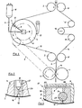
- a rotating application cylinder 4 is used to apply the cross-gluing 17, the circumference of which corresponds exactly to the predetermined distance between the cross-gluing 17. This applies when the application cylinder 4 has a single row of holes 7 through which the adhesive emerges under the action of centrifugal force. However, it is also possible for the application cylinder 4 to contain two or more such rows of bores 7 which are at the same distance from one another. spell the scope of the application cylinder 4 is a whole multiple of the distance between the cross-banding 17th
- the web 2 to be coated is guided with the aid of the deflection roller 3 in such a way that the application cylinder 4 is wrapped in the web 2 in a not inconsiderable part of its circumference. In the area of this wrapping, the row of holes 7 is accordingly covered by the web 2.
- the other web 14 is guided in the usual way over the guide rollers 15 and can be changed by means of the register roller 16 in such a way that a registration accuracy of certain points of the webs 2, 14 can be set. So that the peripheral speeds of the pull rollers 1 and the application cylinder 4 are constant, the application cylinder 4 is driven by the pull roller 1 via the gear 5 in connection with a correspondingly dimensioned driven wheel 6.
- the adhesive to be applied is located in a stationary collecting container 12 and arrives via the adhesive line 11 to a stationary adhesive connection 10, from where the adhesive is supplied to a radial connecting channel 9 via an axial bore 30 in the cylinder shaft 28 (see FIG. 4). which opens into an adhesive feed channel 8, from which the row of holes 7 extends.
- the centrifugal force of the adhesive is counteracted by various forces, one of the most important of which is the capillary force in the outlet openings of the row of holes 7.
- the outlet openings 18 are designed as simple bores with a diameter of approximately 0.8 mm without narrowing.
- the individual outlet opening 18 is designed as a throttle nozzle which, starting from the adhesive feed channel 8, has a bore constriction 20 which widens again into a bore outlet 19.
- the adhesive feed channel 8 is located in an exchangeable insert 21, which is inserted in a corresponding recess in the application cylinder 4 and is supplied with adhesive via the radial connecting channel 9. It has proven to be advantageous to design the bore outlet 19 to be approximately 1 mm long and with a diameter of approximately 0.8 mm, whereas the bore constriction 20 can be, for example, 2 mm to 4 mm long and a diameter of only approximately 0.3 mm having.
- the constriction 20 counteracts the centrifugal force of the adhesive located in the constriction 20 when the application cylinder 4 rotates.
- the throttle nozzle is covered on the outside by the web 2. This means that the adhesive can only bubble out slowly. Even if the outlet opening 18 is not covered by the web 2, the rotation of the up leads carrying cylinder 4 does not cause the adhesive to be thrown off. It is only advisable to cover the outlet openings 18 from the outside during longer breaks in work. For this reason, the covering device 13 is provided in FIG. When work is interrupted, the application cylinder 4 is uncoupled from its drive 5, 6 and brought into a position in which the row of holes 7 is opposite the cover device 13. It is sufficient to prevent air from entering the outlet openings 18 from the outside.
- the position of the cover device 13 can be changed due to the design. It can also be provided with a lifting or swiveling drive, not shown.
- the adhesive is preferably supplied from the collecting container 12 to the application cylinder 4 under pressure, so that if the cover 13 is disregarded, the adhesive could gradually exude.
- the application cylinder 4 is first brought back into its original position in order to bring about the registration accuracy of the cross-gluing 17 with respect to the position of the webs 2, 14.
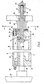
- FIG. 3 being an enlarged partial cross section of the application container. ters 4 along the line III - III. in Figure 4.
- the connecting channel 9 opens into an adhesive supply channel 8, which extends along a surface line of the application cylinder 4 and, in the example of FIG. 3, is formed by a hollow insert 21, the hollow strip 22 of which is closed on the inside by a cover 23.
- This arrangement 22, 23 is firmly inserted into a corresponding recess in the application cylinder 4, but is interchangeable.
- a control shaft 24 extending longitudinally therein is arranged and rotatable in the adhesive feed channel 8 stored. This carries on its periphery a closure element 25 in the form of a strip-shaped sealing lip which is set against the inside of the outlet openings 18. It is advisable to provide the control shaft 24 with an adjustable bearing so that the required sealing effect is brought about.
- the sealing lip (closure element) 25 can also be guided in a radially movable manner on the control shaft 24 and pressed on with springs. Between the control shaft 24 and the corresponding bore of the feed channel 8 there is a play 26 through which the adhesive can pass from the feed channel 8 to the outlet openings 18 when the closure element 25 has opened the outlet openings 18 by rotating the control shafts 24.
- a cylinder shaft 28 is rotatably supported in bearing plates 27 via bearings 52, which supports the jacket of the cylinder via flanges 29.
- the connecting channel 9 extends in the radial direction, which can be formed by a tube 41.
- the axial bore 30 opens into the fixed adhesive connection 10, specifically in its hollow shaft 53, which is mounted with the aid of the bearing 31 and is sealed via the seals 32.
- the hollow shaft 53 of the adhesive connection 10 is connected to the cylinder shaft 28.
- the screw connection 10 can easily be replaced by a screw connection, not shown.
- the adhesive feed channel 8 is provided with an outlet connection 35, which is actuated for cleaning or emptying the application cylinder 4 or the adhesive feed channel 8.
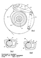
- a gear mechanism shown in FIG. 5 is provided for the oscillating control movement of the control shaft 24.
- On the control shaft 24 is a rocker arm 36, which is provided with a cam roller 39 and is loaded by a spring 40.
- This cam roller 39 rotates with the rocker arm 36 about the axis of the application cylinder 4 and rolls on a fixed cam 37.
- FIG. 4 shows that this cam plate 37 is connected in a fixed manner to the end shield 27 via a connecting sleeve 38.
- the cam disc 37 is designed so that the control shaft 24 is rotated to release the outlet openings 18 (see FIG. 3) as long as the row of holes 7 is covered by the web 2 surrounding the application cylinder 4.
- the application cylinder 4 is essentially hollow and, if necessary, stiffened in places by webs.
- control shaft executes an oscillating rotary movement to open or close the outlet openings 18.
- the control can also be brought about by a rotary movement of the control shaft 24.
- a gear 43 sits on the control shaft 24, which is connected via an idler gear 44 to a stationary drive pinion 45 and rolls on it.
- This drive pinion 45 can be connected to the end shield 27 in a manner similar to the cam disk 37. It is essential that the control shaft 24 executes one revolution with respect to the application cylinder 4 when the application cylinder 4 rotates. The direction of rotation of the control shaft 24 can can be chosen arbitrarily.
- the closure element 24 is then to be designed in such a way that the outlet openings 18 are only opened when the row of openings 7 is covered by the web 2.
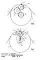
- FIGS. 7 and 8 show the locking and opening position of the control shaft 24 with its closure element 25.
- adjustment mechanisms (not shown) can be provided on the adjusting drives of the control shaft 24.
- the intensity of the adhesive outlet from the outlet openings 18 can also be influenced by further measures which are generally referred to in the invention as metering arrangements.
- the functional relationship between centrifugal force and rotational speed of the application cylinder 4 can be influenced by exposing the adhesive to be supplied to a negative or positive pressure control. This can be done, for example, by changing the pressure conditions in the collecting container 12. Fig. 1 take place.
- a control is shown schematically, in which a valve 48 is present in the connecting channel 9, which prevents the flow of adhesive from the axial bore 30 to the adhesive supply channel 8.
- the adhesive feed channel 8 should only be partially filled. With 51 the adhesive reservoir is designated.
- the valve 48 is actuated so that a The adhesive flows into the feed channel 8. This can take place, for example, via a bypass line (not shown), the valve 48 being axially displaceable in the connecting channel 9.
- FIG. 9 shows only one way of constructively solving the problem described.
Landscapes
- Coating Apparatus (AREA)
- Application Of Or Painting With Fluid Materials (AREA)
- Treatment Of Fiber Materials (AREA)
Applications Claiming Priority (2)
| Application Number | Priority Date | Filing Date | Title |
|---|---|---|---|
| DE3222335 | 1982-06-14 | ||
| DE3222335A DE3222335C2 (de) | 1982-06-14 | 1982-06-14 | Vorrichtung zum Auftragen eines Klebstoffes in Form einer Queranleimung auf eine Bahn |
Publications (3)
| Publication Number | Publication Date |
|---|---|
| EP0096832A2 true EP0096832A2 (fr) | 1983-12-28 |
| EP0096832A3 EP0096832A3 (en) | 1984-11-07 |
| EP0096832B1 EP0096832B1 (fr) | 1986-09-10 |
Family
ID=6166039
Family Applications (1)
| Application Number | Title | Priority Date | Filing Date |
|---|---|---|---|
| EP83105590A Expired EP0096832B1 (fr) | 1982-06-14 | 1983-06-07 | Dispositif de collage transversal pour bandes entraînées à haute vitesse |
Country Status (7)
| Country | Link |
|---|---|
| US (1) | US4502912A (fr) |
| EP (1) | EP0096832B1 (fr) |
| JP (1) | JPS5959264A (fr) |
| CA (1) | CA1196493A (fr) |
| DD (1) | DD209981A5 (fr) |
| DE (2) | DE3222335C2 (fr) |
| ES (1) | ES8403334A1 (fr) |
Cited By (10)
| Publication number | Priority date | Publication date | Assignee | Title |
|---|---|---|---|---|
| EP0369348A3 (fr) * | 1988-11-15 | 1991-01-23 | Baldwin-Gegenheimer GmbH | Dispositif pour appliquer une bande adhésif |
| EP0336358A3 (fr) * | 1988-04-04 | 1991-07-03 | Somar Corporation | Dispositif de lamination des films minces |
| EP0477769A3 (en) * | 1990-09-25 | 1992-08-05 | Albert-Frankenthal Ag | Transverse glueing device for the application of glue on a moving web |
| DE29502723U1 (de) * | 1995-02-18 | 1996-06-20 | Planatol Klebetechnik GmbH, 83101 Rohrdorf | Behandlungsvorrichtung, insbesondere Querleimwerk |
| US5647949A (en) * | 1992-08-11 | 1997-07-15 | Albert-Frankenthal Aktiengesellschaft | Folder for web-fed printing presses |
| DE29712377U1 (de) * | 1997-07-12 | 1998-06-10 | Planatol Klebetechnik GmbH, 83101 Rohrdorf | Querleimwerk für laufende Bahnen |
| EP0880999A3 (fr) * | 1997-05-27 | 1998-12-16 | Martin Christian Oepen | Dispositif d'encollage transversal de produits imprimés |
| US8753737B2 (en) | 2009-05-19 | 2014-06-17 | The Procter & Gamble Company | Multi-ply fibrous structures and methods for making same |
| US9243368B2 (en) | 2009-05-19 | 2016-01-26 | The Procter & Gamble Company | Embossed fibrous structures and methods for making same |
| EP3680024A1 (fr) * | 2014-07-03 | 2020-07-15 | FRAUNHOFER-GESELLSCHAFT zur Förderung der angewandten Forschung e.V. | Module d'application d'un milieu visqueux à une surface et procédé de fabrication de module |
Families Citing this family (12)
| Publication number | Priority date | Publication date | Assignee | Title |
|---|---|---|---|---|
| DE3525805A1 (de) * | 1985-07-19 | 1987-01-29 | Hesselmann Planatolwerk H | Vorrichtung zum auftragen eines klebstoffes in form einer queranleimung |
| DE3527660A1 (de) * | 1985-08-01 | 1987-02-12 | Hesselmann Planatolwerk H | Verfahren und vorrichtung zur herstellung mehrseitiger, gefalzter und verklebter blattlagen |
| JPH069672B2 (ja) * | 1985-10-18 | 1994-02-09 | 富士写真フイルム株式会社 | 磁性液塗布方法 |
| US4724170A (en) * | 1986-09-02 | 1988-02-09 | The Goodyear Tire & Rubber Company | Apparatus and method for applying cement to an end portion of a flexible strip |
| JPH0390671U (fr) * | 1989-12-27 | 1991-09-17 | ||
| JPH0671201U (ja) * | 1991-01-31 | 1994-10-04 | 株式会社マツショウ | トラック用ホイールキャップ |
| US5328544A (en) * | 1993-04-21 | 1994-07-12 | James River Paper Companey, Inc. | System for applying adhesive to sheet material |
| DE19720982B4 (de) * | 1997-05-20 | 2009-08-13 | Hhs Leimauftrags-Systeme Gmbh | Vorrichtung zum Auftragen von Leim |
| US20100030174A1 (en) * | 2008-08-04 | 2010-02-04 | Buschur Patrick J | Multi-ply fibrous structures and processes for making same |
| US20100028621A1 (en) * | 2008-08-04 | 2010-02-04 | Thomas Timothy Byrne | Embossed fibrous structures and methods for making same |
| US20100297395A1 (en) * | 2009-05-19 | 2010-11-25 | Andre Mellin | Fibrous structures comprising design elements and methods for making same |
| US20100297378A1 (en) * | 2009-05-19 | 2010-11-25 | Andre Mellin | Patterned fibrous structures and methods for making same |
Family Cites Families (12)
| Publication number | Priority date | Publication date | Assignee | Title |
|---|---|---|---|---|
| DE1037251B (de) * | 1954-01-16 | 1958-08-21 | Willy Hesselmann | Vorrichtung zur Erzeugung duenner Belaege, vornehmlich aus Klebstoff, auf Bahnen von Papier, Pappe, Stoffen od. dgl. |
| DE1115120B (de) * | 1957-02-21 | 1961-10-12 | Willy Hesselmann | Vorrichtung zum Antragen von fluessigen Stoffen, vornehmlich Klebstoff |
| DE1047968B (de) * | 1957-06-08 | 1958-12-31 | Beiersdorf & Co Ag P | Verfahren und Vorrichtung zur Herstellung von flaechenmaessig begrenzten Klebstoffaufstrichen |
| DE1097349B (de) * | 1959-07-16 | 1961-01-12 | Kronseder Hermann | Beleimvorrichtung fuer schnell laufende Etikettiermaschinen |
| US3332580A (en) * | 1965-09-20 | 1967-07-25 | Lockwood Tech | Fluid applicator valve |
| US3507650A (en) * | 1966-01-11 | 1970-04-21 | Polaroid Corp | Method of depositing viscous photographic reagents |
| DE1561492A1 (de) * | 1967-01-10 | 1970-02-12 | Erhard Klug | Vorrichtung zum Auftragen von Leimpunkten auf laufende Materialbahnen |
| DE1561523A1 (de) * | 1967-12-22 | 1970-05-27 | Windmoeller & Hoelscher | Vorrichtung zum Auftragen von Klebstoff auf Werkstoffbahnen |
| DE2305889C3 (de) * | 1973-02-07 | 1981-02-26 | Bischof Und Klein Gmbh & Co, 4540 Lengerich | Vorrichtung zum insbesondere formatmäßigen Auftragen eines flüssigen oder pastösen Klebstoffs auf ein flaches Werkstück |
| JPS5048929A (fr) * | 1973-05-23 | 1975-05-01 | ||
| US4068618A (en) * | 1976-01-29 | 1978-01-17 | Trufuse International Ltd. | Apparatus for making material with fusible backing |
| JPS5513148A (en) * | 1978-07-15 | 1980-01-30 | Matsushita Electric Works Ltd | Hot melt adhesive coating machine |
-
1982
- 1982-06-14 DE DE3222335A patent/DE3222335C2/de not_active Expired
-
1983
- 1983-06-07 EP EP83105590A patent/EP0096832B1/fr not_active Expired
- 1983-06-07 DE DE8383105590T patent/DE3366037D1/de not_active Expired
- 1983-06-10 US US06/503,315 patent/US4502912A/en not_active Expired - Lifetime
- 1983-06-13 ES ES523202A patent/ES8403334A1/es not_active Expired
- 1983-06-13 CA CA000430240A patent/CA1196493A/fr not_active Expired
- 1983-06-14 JP JP58105102A patent/JPS5959264A/ja active Granted
- 1983-06-14 DD DD83252008A patent/DD209981A5/de not_active IP Right Cessation
Cited By (13)
| Publication number | Priority date | Publication date | Assignee | Title |
|---|---|---|---|---|
| EP0336358A3 (fr) * | 1988-04-04 | 1991-07-03 | Somar Corporation | Dispositif de lamination des films minces |
| EP0369348A3 (fr) * | 1988-11-15 | 1991-01-23 | Baldwin-Gegenheimer GmbH | Dispositif pour appliquer une bande adhésif |
| EP0477769A3 (en) * | 1990-09-25 | 1992-08-05 | Albert-Frankenthal Ag | Transverse glueing device for the application of glue on a moving web |
| US5647949A (en) * | 1992-08-11 | 1997-07-15 | Albert-Frankenthal Aktiengesellschaft | Folder for web-fed printing presses |
| DE29502723U1 (de) * | 1995-02-18 | 1996-06-20 | Planatol Klebetechnik GmbH, 83101 Rohrdorf | Behandlungsvorrichtung, insbesondere Querleimwerk |
| US5876784A (en) * | 1995-02-18 | 1999-03-02 | Planatol Klebetechnik Gmbh | Treatment device, particularly for a transverse sizing machine |
| EP0880999A3 (fr) * | 1997-05-27 | 1998-12-16 | Martin Christian Oepen | Dispositif d'encollage transversal de produits imprimés |
| DE29712377U1 (de) * | 1997-07-12 | 1998-06-10 | Planatol Klebetechnik GmbH, 83101 Rohrdorf | Querleimwerk für laufende Bahnen |
| US8753737B2 (en) | 2009-05-19 | 2014-06-17 | The Procter & Gamble Company | Multi-ply fibrous structures and methods for making same |
| US9243368B2 (en) | 2009-05-19 | 2016-01-26 | The Procter & Gamble Company | Embossed fibrous structures and methods for making same |
| US9701101B2 (en) | 2009-05-19 | 2017-07-11 | The Procter & Gamble Company | Multi-ply fibrous structures and methods for making same |
| US9937694B2 (en) | 2009-05-19 | 2018-04-10 | The Procter & Gamble Company | Method for making multi-ply fibrous structures |
| EP3680024A1 (fr) * | 2014-07-03 | 2020-07-15 | FRAUNHOFER-GESELLSCHAFT zur Förderung der angewandten Forschung e.V. | Module d'application d'un milieu visqueux à une surface et procédé de fabrication de module |
Also Published As
| Publication number | Publication date |
|---|---|
| ES523202A0 (es) | 1984-03-16 |
| JPS5959264A (ja) | 1984-04-05 |
| US4502912A (en) | 1985-03-05 |
| EP0096832A3 (en) | 1984-11-07 |
| DE3366037D1 (en) | 1986-10-16 |
| JPH0575599B2 (fr) | 1993-10-20 |
| DE3222335C2 (de) | 1985-01-03 |
| DD209981A5 (de) | 1984-05-30 |
| ES8403334A1 (es) | 1984-03-16 |
| EP0096832B1 (fr) | 1986-09-10 |
| DE3222335A1 (de) | 1983-12-15 |
| CA1196493A (fr) | 1985-11-12 |
Similar Documents
| Publication | Publication Date | Title |
|---|---|---|
| EP0096832B1 (fr) | Dispositif de collage transversal pour bandes entraînées à haute vitesse | |
| DE1652402A1 (de) | Verfahren und Vorrichtung zum Beschichten von Baendern | |
| DE102004058542A1 (de) | Rotationsauftragskopf und Etikettieranlage zum Aufbringen von Etiketten | |
| DE3102139A1 (de) | "druckpresse zum bedrucken von blaettern, insbesondere aus wellpappe" | |
| DE2611262A1 (de) | Vorrichtung zur verteilung eines druckmittels und einer waschfluessigkeit an einer druckerpresse | |
| DE2105297A1 (de) | Einrichtung zum Imprägnieren von in Längsrichtung vorbewegtem Wellkarton | |
| WO2015010762A1 (fr) | Dispositif permettant de produire des emballages pour cigarettes et pourvu d'un ensemble soupape | |
| EP1864801A1 (fr) | Imprimé d'une presse | |
| EP0901839B1 (fr) | Dispositif pour l'application de fluides sur un substrat | |
| EP1644195A2 (fr) | Rouleau pour dispositif d'encrage ou de mouillage | |
| DE1954316A1 (de) | Verfahren und Einrichtung zum Beschicken von Walzen in Druckwerken von Druckmaschinen mit einem fluessigen Medium,z.B. Farbe,und zum Dosieren des Mediums | |
| DE102007015401A1 (de) | Feuchtwerk für ein Druckwerk einer Druckmaschine | |
| DE4143003A1 (de) | Vorrichtung zum querfalten von bahnen oder bahnabschnitten aus papier, tissue, nonwoven oder dergleichen | |
| DE3823179C1 (fr) | ||
| DE68912289T2 (de) | Papierbeschichtung. | |
| DE2132850A1 (de) | Rotationsoffsetdruckmaschineneinheit | |
| DE2365668C3 (de) | Vorrichtung zur Verarbeitung bahnförmigen Materials mit einem Rotationsdruckwerk | |
| DE967549C (de) | Abfuell- und Schliessmaschine, insbesondere fuer Tuben | |
| DE10322320B4 (de) | Ventilanordnung für Sprühfeuchtwerke von Druckmaschinen | |
| DE102007015404B4 (de) | Feuchtwerk für ein Druckwerk einer Druckmaschine | |
| DE2442478A1 (de) | Vorrichtung zum aufbringen von leim fuer eine vielbahnige papierzufuehrmaschine | |
| DE3005920C2 (fr) | ||
| DE593016C (de) | Vorrichtung zum Auftragen einer elastischen Schicht aus plastischer Masse auf die Einzelscheiben von nicht splitternden Glaesern | |
| DE324319C (de) | Vorrichtung zum einseitigen UEberziehen von Gewebebahnen mit zaehfluessiger Masse zur Herstellung von Wachstuchen, Kunstleder u. dgl. | |
| DE767019C (de) | Vorrichtung zur Farbfuehrung fuer Rotationsschablonendrucker |
Legal Events
| Date | Code | Title | Description |
|---|---|---|---|
| PUAI | Public reference made under article 153(3) epc to a published international application that has entered the european phase |
Free format text: ORIGINAL CODE: 0009012 |
|
| AK | Designated contracting states |
Designated state(s): BE CH DE FR GB IT LI NL SE |
|
| PUAL | Search report despatched |
Free format text: ORIGINAL CODE: 0009013 |
|
| AK | Designated contracting states |
Designated state(s): BE CH DE FR GB IT LI NL SE |
|
| 17P | Request for examination filed |
Effective date: 19841129 |
|
| GRAA | (expected) grant |
Free format text: ORIGINAL CODE: 0009210 |
|
| AK | Designated contracting states |
Kind code of ref document: B1 Designated state(s): BE CH DE FR GB IT LI NL SE |
|
| REF | Corresponds to: |
Ref document number: 3366037 Country of ref document: DE Date of ref document: 19861016 |
|
| ET | Fr: translation filed | ||
| ITF | It: translation for a ep patent filed | ||
| PLBE | No opposition filed within time limit |
Free format text: ORIGINAL CODE: 0009261 |
|
| STAA | Information on the status of an ep patent application or granted ep patent |
Free format text: STATUS: NO OPPOSITION FILED WITHIN TIME LIMIT |
|
| 26N | No opposition filed | ||
| ITTA | It: last paid annual fee | ||
| EAL | Se: european patent in force in sweden |
Ref document number: 83105590.0 |
|
| PGFP | Annual fee paid to national office [announced via postgrant information from national office to epo] |
Ref country code: GB Payment date: 20000522 Year of fee payment: 18 |
|
| PGFP | Annual fee paid to national office [announced via postgrant information from national office to epo] |
Ref country code: FR Payment date: 20000616 Year of fee payment: 18 |
|
| PGFP | Annual fee paid to national office [announced via postgrant information from national office to epo] |
Ref country code: NL Payment date: 20000620 Year of fee payment: 18 |
|
| PGFP | Annual fee paid to national office [announced via postgrant information from national office to epo] |
Ref country code: CH Payment date: 20000623 Year of fee payment: 18 Ref country code: BE Payment date: 20000623 Year of fee payment: 18 |
|
| PGFP | Annual fee paid to national office [announced via postgrant information from national office to epo] |
Ref country code: SE Payment date: 20000626 Year of fee payment: 18 |
|
| PG25 | Lapsed in a contracting state [announced via postgrant information from national office to epo] |
Ref country code: GB Free format text: LAPSE BECAUSE OF NON-PAYMENT OF DUE FEES Effective date: 20010607 |
|
| PG25 | Lapsed in a contracting state [announced via postgrant information from national office to epo] |
Ref country code: SE Free format text: LAPSE BECAUSE OF NON-PAYMENT OF DUE FEES Effective date: 20010608 |
|
| PG25 | Lapsed in a contracting state [announced via postgrant information from national office to epo] |
Ref country code: LI Free format text: LAPSE BECAUSE OF NON-PAYMENT OF DUE FEES Effective date: 20010630 Ref country code: CH Free format text: LAPSE BECAUSE OF NON-PAYMENT OF DUE FEES Effective date: 20010630 Ref country code: BE Free format text: LAPSE BECAUSE OF NON-PAYMENT OF DUE FEES Effective date: 20010630 |
|
| BERE | Be: lapsed |
Owner name: PLANATOLWERK WILLY HESSELMANN CHEMISCHE UND MASCH Effective date: 20010630 |
|
| PG25 | Lapsed in a contracting state [announced via postgrant information from national office to epo] |
Ref country code: NL Free format text: LAPSE BECAUSE OF NON-PAYMENT OF DUE FEES Effective date: 20020101 |
|
| GBPC | Gb: european patent ceased through non-payment of renewal fee |
Effective date: 20010607 |
|
| EUG | Se: european patent has lapsed |
Ref document number: 83105590.0 |
|
| REG | Reference to a national code |
Ref country code: CH Ref legal event code: PL |
|
| PG25 | Lapsed in a contracting state [announced via postgrant information from national office to epo] |
Ref country code: FR Free format text: LAPSE BECAUSE OF NON-PAYMENT OF DUE FEES Effective date: 20020228 |
|
| NLV4 | Nl: lapsed or anulled due to non-payment of the annual fee |
Effective date: 20020101 |
|
| PGFP | Annual fee paid to national office [announced via postgrant information from national office to epo] |
Ref country code: DE Payment date: 20020621 Year of fee payment: 20 |