EP0096853A1 - Mechanische Liefervorrichtung für Papierbogen - Google Patents
Mechanische Liefervorrichtung für Papierbogen Download PDFInfo
- Publication number
- EP0096853A1 EP0096853A1 EP83105663A EP83105663A EP0096853A1 EP 0096853 A1 EP0096853 A1 EP 0096853A1 EP 83105663 A EP83105663 A EP 83105663A EP 83105663 A EP83105663 A EP 83105663A EP 0096853 A1 EP0096853 A1 EP 0096853A1
- Authority
- EP
- European Patent Office
- Prior art keywords
- stack
- pinion
- arms
- paper
- sheet
- Prior art date
- Legal status (The legal status is an assumption and is not a legal conclusion. Google has not performed a legal analysis and makes no representation as to the accuracy of the status listed.)
- Withdrawn
Links
- 230000007246 mechanism Effects 0.000 claims abstract description 41
- 230000005540 biological transmission Effects 0.000 claims description 21
- 230000008878 coupling Effects 0.000 claims description 15
- 238000010168 coupling process Methods 0.000 claims description 15
- 238000005859 coupling reaction Methods 0.000 claims description 15
- 230000001133 acceleration Effects 0.000 claims description 5
- 238000011144 upstream manufacturing Methods 0.000 claims description 2
- 230000002401 inhibitory effect Effects 0.000 claims 1
- 230000001131 transforming effect Effects 0.000 claims 1
- 230000010355 oscillation Effects 0.000 description 6
- 230000009471 action Effects 0.000 description 3
- 230000002093 peripheral effect Effects 0.000 description 3
- 230000003028 elevating effect Effects 0.000 description 2
- 229910000831 Steel Inorganic materials 0.000 description 1
- 230000008859 change Effects 0.000 description 1
- 238000006243 chemical reaction Methods 0.000 description 1
- 230000006835 compression Effects 0.000 description 1
- 238000007906 compression Methods 0.000 description 1
- 125000004122 cyclic group Chemical group 0.000 description 1
- 230000007423 decrease Effects 0.000 description 1
- 238000010586 diagram Methods 0.000 description 1
- 235000021183 entrée Nutrition 0.000 description 1
- 238000012423 maintenance Methods 0.000 description 1
- 230000004048 modification Effects 0.000 description 1
- 238000012986 modification Methods 0.000 description 1
- 230000009467 reduction Effects 0.000 description 1
- 230000000284 resting effect Effects 0.000 description 1
- 239000011435 rock Substances 0.000 description 1
- 239000010959 steel Substances 0.000 description 1
- 230000007704 transition Effects 0.000 description 1
Images

Classifications
-
- B—PERFORMING OPERATIONS; TRANSPORTING
- B65—CONVEYING; PACKING; STORING; HANDLING THIN OR FILAMENTARY MATERIAL
- B65H—HANDLING THIN OR FILAMENTARY MATERIAL, e.g. SHEETS, WEBS, CABLES
- B65H5/00—Feeding articles separated from piles; Feeding articles to machines
- B65H5/06—Feeding articles separated from piles; Feeding articles to machines by rollers or balls, e.g. between rollers
- B65H5/062—Feeding articles separated from piles; Feeding articles to machines by rollers or balls, e.g. between rollers between rollers or balls
-
- B—PERFORMING OPERATIONS; TRANSPORTING
- B65—CONVEYING; PACKING; STORING; HANDLING THIN OR FILAMENTARY MATERIAL
- B65H—HANDLING THIN OR FILAMENTARY MATERIAL, e.g. SHEETS, WEBS, CABLES
- B65H2403/00—Power transmission; Driving means
- B65H2403/40—Toothed gearings
Definitions
- the present invention relates to a mechanical assembly adapted to supply sheets of paper taken one after the other from a stack, for example, a printing machine, a stencil reproduction machine or an electrophotographic reproduction machine, in which the sheets must pass through a narrow window or the gap existing between a drum or a cylinder carrying an image, driven in rotation, and a printing or image transfer roller so that the image is transferred to the leaves.
- the mechanical assembly can, however, find other applications.
- the object of the present invention is to produce a mechanical supply assembly for a printing or reproduction machine with a rotary drum, in which the drive means specific to this mechanical supply assembly develop from the constant angular speed of the machine drum, called constant angular speed of entry for these drive means, an angular speed called exit for these drive means which varies cyclically to allow the individual removal of the sheets from the stack and then their drive for regular and almost continuous feeding of the machine.
- Such an arrangement makes it possible to obtain a positioning accuracy of the sheet of paper when it enters the feed path of the machine and guarantees synchronism between the arrival of successive sheets in the machine and the start of the image. carried by the drum.
- the subject of the present invention is therefore a mechanical assembly for feeding sheets of paper taken one after the other from a stack, intended for feeding a rotary drum machine, comprising a feeding station, having a tray receiving the stack of sheets and means for separating the upper sheet from the stack, and a feeding mechanism having a pair of rollers for driving the sheets successively separated to the rotary drum of the machine, characterized by fact that said mechanism comprises first motor means driven with said drum at substantially constant angular speed, substantially second transmission means controlling one of the rollers of said pair, said first roller, and coupling means coupling said first motor means and said second transmission means for printing on the first roller a angular speed which varies, cyclically and with low acceleration, from a zero value to a maximum value substantially equal to the tangential speed of the drum.
- said mechanism further comprises, upstream of said pair of rollers, a feed bar, arranged transversely to the mechanical assembly above the stack of sheets on the tray and equipped with gripping and driving fingers of the upper sheet of paper, the ends of which are secured to a pair of end plates mounted on a pair of oscillating arms from which they are resiliently secured, so that said bar come and occupy a so-called working position and a so-called rest position relative to the arms, having said fingers which it bears firmly in contact with the paper for the working position and without contact with the paper for the rest position, means for oscillating said arms according to outward and return trajectories for feeding successive sheets from said stack, and tilting means capable of ensuring the placing of the ba supply line in said working position at the end of the return path of said arms and ensuring the supply of the feed bar in said rest position, at the end of the forward path of said arms, said fingers ensuring during said trajectory go the drive of said upper sheet and being without contact with it during the
- the assembly in which the tray carrying the stack of sheets is a lifting tray driven step by step as the sheets are removed from said stack for maintaining the substantially constant level of the upper sheet in said stack and in which the feed station is equipped with vertical lateral guides carrying means for removing the top sheet from the stack is characterized in that the said lateral guides are mounted adjustable along fixed horizontal supports, through windows in said tray, and that said lateral guides, arranged substantially at the front edge of the stack of paper in the station, each carry said take-off means on their upper end part constituted by a lever mounted pivoting on a horizontal axis and biased by a spring so that its lower edge inclined to the horizontal is applied to the edge of said upper sheet in the stack by exerting on this sheet a force tending to detach it from the battery.
- the device for feeding sheets of paper comprises a horizontal lifting platform which carries a stack or ream of paper, the front edge of which comes into contact with a stop device provided with separating corners or the individual sheets, which trap the corners of the top sheet.
- the platform is raised step by step to maintain the top of the stack at a substantially constant level while leaves are being picked.
- a first feeding mechanism drives the upper sheet above the device and the separating corners, so that the corners of this sheet are peeled off from the adjacent sheet of the stack and its front edge comes into contact with a fixed part d a second feeding mechanism while the sheet is in the form of a loop to ensure that its front edge is well disposed against the fixed part of the second feeding mechanism.
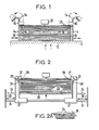
- FIG. 1 For a mechanical assembly of this type, there is illustrated in FIG. 1, a conventional station for feeding sheets of paper.
- This station comprises a horizontal elevating platform 12 and is equipped along the longitudinal edges of the stack of paper with lateral guides 10, adjustable to adapt to different widths of paper; these guides 10 are fixed to the platform 12.
- a level microsensor 22 detects the vertical level of the upper sheet and, while the sheets are taken one after the other from the stack for feeding a printing or reproduction machine, controls the ascent of the platform 12, so that the top sheet in the stack is held at the feed path.
- the weights 16 descend freely along the slides 14 to maintain pressure on the edges of the stack of paper.
- the weights 16 are guided, by hand, to the upper ends of the slides 14, curved downward on the outer sides of the station, on which they come to occupy a position rest.
- the weights 16 are again brought, by hand, onto the vertical portions of the slides 14 and come into contact with the upper sheet of the stack.
- FIG 2 there is illustrated a new arrangement of the feed station entering the mechanical feed assembly according to the invention.
- This station also includes an elevating platform 25 carrying a stack of paper 29 and is equipped with lateral guides 27 along the longitudinal edges of the stack. These guides 27 are no longer fixed to the platform 25, however, but arranged to slide horizontally on supports or guide rods 31 mounted on the side walls 33 of the machine with which the mechanical assembly is associated.
- the platform 25 has windows 34 for the passage of the guides 27. These guides 27 are adjustable in position along the guide rods 31 to adapt to different widths of paper. They are not, however, adjustable in height, the stack of paper will be raised between them.
- a horizontal pivot 35 with an axis parallel to the longitudinal edges of the stack of paper, is mounted on the upper part, substantially at the end, of the guide 27 furthest back in this station.
- Each pivot 35 carries a lever 37 which projects towards the inside of the station and is applied against the edge of the stack of paper.
- the underside of each lever 37 is inclined on the stack of paper, torsion springs 38 concentric with the pivot 35 and fixed between the guides 27 and the levers 37 keep these edges inclined against the edge of the upper sheets, by exerting on the stack of paper a load corresponding to that obtained by a mass of the order of 150 g, for an inclination of approximately 50 0 .
- the levers 37 are in abutment against stop stops 39, in the absence of paper on the platform.
- the platform 25 is lowered and the new stack of paper is loaded, then the platform is raised to its operating level; towards the end of this rise, the levers 37 then automatically press against the edges of the stack of paper, taking their correct inclination and exerting the appropriate load on the upper sheets.
- the need to hand put the aforementioned weights in their rest position and then in their position of contact with the sheet of paper is eliminated, the load variations due to the variable friction forces of the aforementioned weights along their slide are also eliminated, finally the height of the guides is independent of the level of the platform and the height of the station can therefore be reduced.
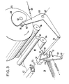
- FIGS. 3, 4A and 4B the first feed mechanism returning to the mechanical feed assembly has been illustrated.
- This first mechanism is associated with the supply station according to Figure 2 to which it follows. There is illustrated the stack of paper 29 carried by its horizontal platform. The front edge of the stack, at the entry of this first feeding mechanism is in abutment against a plate 40 fitted with separating corners 40a, 40b (FIG. 5) which engage on the corners of the front edge of the upper sheet . As indicated above, the platform will be raised step by step to maintain the top sheet of the stack at a substantially constant level as and when the sheets are removed from the stack.
- a first feed element 42 or feed bar, preferably hollow and of rectangular cross section, is mounted perpendicular to the path of movement of the sheets and slightly at the above the stack 29, on end plates 44.
- These plates 44 are secured to substantially vertical arms 48, disposed on each side of the mechanical assembly, and can pivot around a connecting axis 46, located under the bar 42. -These arms 48 can also pivot on a shaft 50, at their lower part.
- the bar 42 is free in oscillation over an angle of about 30 °, relative to the arms 48, stops stop this oscillation. It is biased by a return spring mounted on the arm 48, a pin spring 52, mounted between each plate 44 and the associated arm 48 also provides an elastic connection between the plate and the arm, these connections transform this assembly into a bistable device.
- Elastic fingers 54 for gripping and driving the top sheet in the stack are fixed under the bar 42 and project towards the inside of the mechanism, being slightly inclined downwards; they wear pads 56, of rubber, on the face. lower of their terminal part distant from the bar 42.
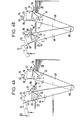
- the pads 56 are applied with pressure against the upper sheet of the stack, this working position being that illustrated in FIG. 4A; on the other hand, in the other state of the device, corresponding to a rest position of the first mechanical assembly illustrated in the Figure 4B, the pads 56 are above the stack of paper and without contact with it.
- the arms 48 are integral, at their lower ends, with the shaft 50 which extends through the mechanical assembly, under the stack of paper 29; this shaft 50 is free to rotate on its supports, not shown.
- the arms 48 are relatively long to allow, while they oscillate, the assimilation of the arcuate trajectory of the bar 42 to a straight line and, in the working position of the first mechanical assembly, the maintenance of the skids rubber 56 in contact with the upper sheet, throughout the oscillation.
- the oscillation drive of the arms 48 is obtained from a cam 60 driven in synchronism with the rotary parts of the reproduction or printing machine to be fed with sheets, for example by being mounted at the end on the motor shaft. 62 of the printing drum or cylinder 64.
- This cam 60 has on its periphery a concavity 60 ′.
- An auxiliary cam 66, or follower roller, is associated with cam 60 on the periphery of which it is supported.
- This follower roller 66 is mounted at one end of a bent shaft 68, pivoting around an axis 68 'at its elbow and solicity towards the outside of the first mechanical assembly by a return spring 69.
- This arm bent with an end follower roller transforms the rotary movement of the cam 60 into an oscillating movement which it transmits, by means of a mechanical connection 70 articulated on the other end of the bent arm, to each end plate 44 which constitutes the tilting upper part of the bistable device.
- a traction exerted on the mechanical connection 70 is transmitted to the end plates 4 4; this traction comes to apply with pressure the pads 56 on the paper but remains however insufficient, when the first mechanical assembly is in rest state, to counteract the action of the spring 52 and to tilt the bistable device in the working state.
- Stops 72 and 74 are provided to cooperate with the front and rear faces 76, 78 of the end plates 44, at the end of the back and forth strokes of the arms 48, to change the state of the bistable device. So the fingers 54 are moved down and put in contact with the paper before each forward trajectory of the arms 48 and are raised before each return trajectory.
- the rearmost stop 72 is however advantageously controlled by an electromagnet as shown diagrammatically by the arrow f (FIG. 4A), so as to allow, when no sheet is to be taken from the stack during the next outward trajectory, the stop 72 rocks and is retracted so that the face 78 of the plates no longer comes into contact with it, while the fingers remain in the high position.
- FIG 3 there is further illustrated an upper sheet 80 released from the stack by the first feeding mechanism and guided until its front edge is introduced into the reduced space or gap between upper and lower rollers. 82 and 84 of the second feeding mechanism, then not driven. This release and guiding action carried out by the first mechanism continues until the sheet 80 bends slightly and forms a loop, after which the rollers 82 and 84 will be rotated with a slight acceleration.
- FIG. 4A the two end positions of this first feeding mechanism have been illustrated for a sheet feeding cycle, called the active cycle.
- the position illustrated on the left of this figure corresponds to the idle state of the mechanism, the position illustrated on the right corresponds to the working state.
- FIG. 4B the two terminal positions of the mechanism have been illustrated, for a cycle without taking paper, said vacuum cycle.
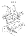
- FIG 5 there is illustrated the active or functional elements of the second feeding mechanism following the first mechanism of Figure 3.
- This second feeding mechanism essentially comprises the pair of rollers 82 and 84 at rest or driven. As soon as they are driven, they advance the sheet 80 (Figure 3); they will be driven at increasing speed until the front edge of the sheet engages between the drum or cylinder 64 and the transfer or printing roller 86 belonging to a printing or reproduction machine with which is associated the mechanical power supply assembly.
- the acceleration transmitted by the rollers 82, 84 to the sheet 80 will be such that when the front edge of this sheet engages between the rollers 64, 86, its speed will be equal to the peripheral speed of the rollers 82, 84.
- the upper roller 82 of the second feed mechanism will be raised to be without contact with the sheet 80, the remaining part of which can pass freely between these rollers, while the rollers 82, 84 will be slowed down to be ready to receive the next sheet taken from the stack.
- the rollers 82 and 84 will be kept “freewheeling" at their maximum speed and will be braked after the sheet 80 has passed.
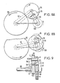
- the suitable cyclic drive means of one of these rollers 82, 84, or roller 84, constituting with these rollers, the second feeding mechanism are illustrated in FIG. 5 and partially in FIG. 9, their equivalent diagram in the form of a deformable loop with four branches is given in FIG. 6.
- the drive means of the roller 84 comprise a first drive pinion 88, coaxial with the drum or cylinder 64, of which it is integral, coupled to a second pinion 90 mounted on a shaft 91 transverse to the second feed mechanism.
- This shaft 91 carries a coupling arm 92 carrying at the end a shaft 93 on which is mounted a third pinion 94 also coupled with the pinion 90.
- the pinions 88, 90 and 94 are arranged in the same first plane.
- a fourth pinion 95 is mounted in a second parallel plane and slightly distant from the first, this pinion 95 is on the one hand carried by a shaft 97 mounted at one end of a second coupling arm 96 and on the other hand secured by a connecting finger 99 to the pinion 94.
- the other end of the coupling arm 96 is pivotally mounted on a shaft 98 which drives the roller 84, this shaft 98 also carries a fifth pinion 100 coupled with the pinion 95.
- the four loop equivalent branches is illustrated in Figure 6. Points A, B, C and D correspond to trees 91, 93, 97 and 98, respectively.
- the branch AD is fixed or of reference, the two branches AB and CD form "connecting rods" on the loop and the branch AD ensures their coupling.
- the pinion 90 constitutes the driving pinion; it is coupled to the pinion 94.
- the pinions 94, 95 are integral with one another but arranged in the parallel planes.
- the pinion 95 drives the pinion 100 which constitutes the transmission pinion.
- the pinion 88 is driven in a clockwise direction
- the pinion 90 is on the other hand driven in a counterclockwise direction, as indicated by the arrows appa growing on these gables.
- the pinions 94 and 95 arranged in different planes are both driven clockwise, taking into account their connection; however, for this drive to take place, the pinion 94 oscillates from top to bottom on the arm 92 and the pinion 95 from back to front on the arm 96.
- the rotation of the pinion 95 is also transmitted to the transmission pinion 100.
- the pinion 95 has a single direction of rotation and that the arm 96 pivots in different angular directions, it follows that in certain states of the drive mechanism, the angular speed of the arm 96 is added to that of the pinion 94 and that in others it is removed from that of the pinion 94 (FIG. 8A) and that in still others it is removed from that of the transmission pinion 100 (FIG. 8B).
- the lengths of the coupling arms and the reduction ratio between pinions are suitably chosen, at one point in the cycle, the drive of pinion 100 is strictly canceled by the angular speed of the coupling arm 96, which results in a real zero speed. .
- the drive of the pinion 100 and the angular speed of the coupling arm 96 accumulate, which gives a maximum speed.
- the upper roller 82 with an elastically compressible peripheral layer, for example made of rubber, is mounted on a first end of a lever 105, which can pivot around an axis 106 on the chassis of the mechanical assembly and the final printing machine or of reproduction.
- This lever is actuated by a roller 107, carried by its second end, which is engaged on a cam 108 driven in synchronism with the drum 64.
- the cam 108 and the roller 107 act to lift the roller 82, which is no longer in contact with the roller 84, for a suitable period of time, depending on the length of the sheet of paper.
Landscapes
- Engineering & Computer Science (AREA)
- Mechanical Engineering (AREA)
- Sheets, Magazines, And Separation Thereof (AREA)
Applications Claiming Priority (2)
| Application Number | Priority Date | Filing Date | Title |
|---|---|---|---|
| GB08217468A GB2121769A (en) | 1982-06-16 | 1982-06-16 | Sheet feed mechanism |
| GB8217468 | 1982-06-16 |
Publications (1)
| Publication Number | Publication Date |
|---|---|
| EP0096853A1 true EP0096853A1 (de) | 1983-12-28 |
Family
ID=10531090
Family Applications (1)
| Application Number | Title | Priority Date | Filing Date |
|---|---|---|---|
| EP83105663A Withdrawn EP0096853A1 (de) | 1982-06-16 | 1983-06-09 | Mechanische Liefervorrichtung für Papierbogen |
Country Status (3)
| Country | Link |
|---|---|
| EP (1) | EP0096853A1 (de) |
| JP (1) | JPS597641A (de) |
| GB (1) | GB2121769A (de) |
Cited By (4)
| Publication number | Priority date | Publication date | Assignee | Title |
|---|---|---|---|---|
| GB2176173A (en) * | 1985-06-10 | 1986-12-17 | Malcolm Rogers | Feeding paper to a shredding machine |
| GB2236097A (en) * | 1989-08-10 | 1991-03-27 | Rotaprint Ind Limited | Sheet handling devices |
| CN116556106A (zh) * | 2023-05-17 | 2023-08-08 | 东莞金洲纸业有限公司 | 一种造纸施胶机传动控制程序及其造纸施胶机 |
| CN116971088A (zh) * | 2023-09-25 | 2023-10-31 | 江苏省香川绳缆科技有限公司 | 一种用于整理绳缆编织料的辊轴 |
Families Citing this family (4)
| Publication number | Priority date | Publication date | Assignee | Title |
|---|---|---|---|---|
| SE452756B (sv) * | 1985-03-04 | 1987-12-14 | Eka Nobel Ab | Forfarande for framstellning av klordioxid |
| GB8929365D0 (en) * | 1989-12-30 | 1990-02-28 | Alcatel Business Systems | Article feeding |
| JP5895664B2 (ja) * | 2012-03-30 | 2016-03-30 | ブラザー工業株式会社 | 給紙装置 |
| JP6070043B2 (ja) | 2012-03-30 | 2017-02-01 | ブラザー工業株式会社 | 画像形成装置 |
Citations (4)
| Publication number | Priority date | Publication date | Assignee | Title |
|---|---|---|---|---|
| FR2205049A5 (de) * | 1972-10-25 | 1974-05-24 | Ricoh Kk | |
| DE2457112B2 (de) * | 1973-12-27 | 1978-10-26 | Ricoh Co., Ltd., Tokio | Blatttransportvorrichtung |
| DE2947709A1 (de) * | 1979-02-13 | 1980-08-21 | Simon Container Mach Ltd | System zum zufuehren von boegen aus einem stapel |
| US4331328A (en) * | 1980-06-30 | 1982-05-25 | Burroughs Corporation | Controller for a servo driven document feeder |
-
1982
- 1982-06-16 GB GB08217468A patent/GB2121769A/en not_active Withdrawn
-
1983
- 1983-06-09 EP EP83105663A patent/EP0096853A1/de not_active Withdrawn
- 1983-06-15 JP JP10759683A patent/JPS597641A/ja active Pending
Patent Citations (4)
| Publication number | Priority date | Publication date | Assignee | Title |
|---|---|---|---|---|
| FR2205049A5 (de) * | 1972-10-25 | 1974-05-24 | Ricoh Kk | |
| DE2457112B2 (de) * | 1973-12-27 | 1978-10-26 | Ricoh Co., Ltd., Tokio | Blatttransportvorrichtung |
| DE2947709A1 (de) * | 1979-02-13 | 1980-08-21 | Simon Container Mach Ltd | System zum zufuehren von boegen aus einem stapel |
| US4331328A (en) * | 1980-06-30 | 1982-05-25 | Burroughs Corporation | Controller for a servo driven document feeder |
Cited By (5)
| Publication number | Priority date | Publication date | Assignee | Title |
|---|---|---|---|---|
| GB2176173A (en) * | 1985-06-10 | 1986-12-17 | Malcolm Rogers | Feeding paper to a shredding machine |
| GB2236097A (en) * | 1989-08-10 | 1991-03-27 | Rotaprint Ind Limited | Sheet handling devices |
| CN116556106A (zh) * | 2023-05-17 | 2023-08-08 | 东莞金洲纸业有限公司 | 一种造纸施胶机传动控制程序及其造纸施胶机 |
| CN116971088A (zh) * | 2023-09-25 | 2023-10-31 | 江苏省香川绳缆科技有限公司 | 一种用于整理绳缆编织料的辊轴 |
| CN116971088B (zh) * | 2023-09-25 | 2023-12-01 | 江苏省香川绳缆科技有限公司 | 一种用于整理绳缆编织料的辊轴 |
Also Published As
| Publication number | Publication date |
|---|---|
| JPS597641A (ja) | 1984-01-14 |
| GB2121769A (en) | 1984-01-04 |
Similar Documents
| Publication | Publication Date | Title |
|---|---|---|
| EP0388318B1 (de) | Verfahren und Vorrichtung zum Bilden eines neuen Stapels nach dem Abnehmen von einem fertigen Stapel, in einer, insbesondere einem Printer zugeordneten, Stapelbildungsmaschine | |
| EP0122817B1 (de) | Verfahren und Vorrichtung zum automatischen Beschicken einer Maschine zur Behandlung von flachen Gegenständen | |
| EP0451592B1 (de) | Verfahren und Vorrichtung zum Bilden von Stapeln von der Oberseite eines Stapels von Blättern in einer Maschine zur Herstellung von Verpackungen | |
| EP0095423B1 (de) | Offset-Druckapparat für verschiedene Formate | |
| EP3612484B1 (de) | Vorrichtung zur probebgenentnahme , entsorgungsstation, und maschine zur bearbeitung von bogenförmigen gegenständen | |
| EP3612483B1 (de) | Vorrichtung und verfahren zur kontrolle von probebögen, entsorgungsstation, und maschine zur bearbeitung von bogenförmigen gegenständen | |
| EP2391501B1 (de) | Biegevorrichtung und -verfahren für biege-klebe-presse | |
| FR2562526A1 (fr) | Chargeur de signatures, feuilles et produits similaires pour alimentateurs pour machines de conditionnement, de machines pour la reliure et analogues | |
| CH621530A5 (de) | ||
| CH676702A5 (de) | ||
| CH633761A5 (fr) | Dispositif pour empiler des objets plats, notamment des decoupes de boites pliantes. | |
| EP2704973B1 (de) | Vorrichtung zum stapeln von papierbögen oder dergleichen | |
| WO2017153055A1 (fr) | Tendeur de chaines, machine de traitement d'elements en forme de feuilles et procede pour tendre les trains de chaines | |
| EP0638496B1 (de) | Vorrichtung und Verfahren zum Einführen von blattformigem Material in eine Maschine | |
| EP1989115B1 (de) | Vorrichtung zum füllen eines behälters | |
| EP0130852A1 (de) | Vorrichtung zum Anfertigen von Pappkisten in gefalteter Form | |
| EP3612482B1 (de) | Vorrichtung und verfahren zum auslegen von probebogen, entsorgungsstation und maschine zur bearbeitung von elementen in form von blättern | |
| FR2549025A1 (fr) | Procede et dispositif pour la formation de piles d'articles plats et flexibles, en particulier des imprimes | |
| FR2641769A1 (fr) | Appareil de manutention de feuilles pour agrafage de groupes de feuilles | |
| FR2597847A1 (fr) | Machine de reception et d'empilage de flans decoupes | |
| EP0620088A1 (de) | Papierschneidvorrichtung | |
| FR2655961A1 (fr) | Margeur de feuilles avec pile auxiliaire pour marche continue. | |
| EP0337039A1 (de) | Maschine zur Handhabung von flachen Gegenständen insbesondere Tüten oder Tütchen, bei der Ausgabe aus einer Herstellungsmaschine | |
| EP0453984A2 (de) | Vorrichtung zum Einrütteln von Blättern | |
| EP0453983A1 (de) | Vorrichtung zum Auffangen aufzustapelnder Bögen in einer Maschine zur Herstellung von Verpackungen |
Legal Events
| Date | Code | Title | Description |
|---|---|---|---|
| PUAI | Public reference made under article 153(3) epc to a published international application that has entered the european phase |
Free format text: ORIGINAL CODE: 0009012 |
|
| AK | Designated contracting states |
Designated state(s): BE DE FR GB IT LU NL SE |
|
| 17P | Request for examination filed |
Effective date: 19840626 |
|
| STAA | Information on the status of an ep patent application or granted ep patent |
Free format text: STATUS: THE APPLICATION IS DEEMED TO BE WITHDRAWN |
|
| 18D | Application deemed to be withdrawn |
Effective date: 19850529 |
|
| RIN1 | Information on inventor provided before grant (corrected) |
Inventor name: ATKINSON, CYRIL JOHN |