EP0096874B1 - Gehäuse für Mikrowellenherd - Google Patents
Gehäuse für Mikrowellenherd Download PDFInfo
- Publication number
- EP0096874B1 EP0096874B1 EP83105724A EP83105724A EP0096874B1 EP 0096874 B1 EP0096874 B1 EP 0096874B1 EP 83105724 A EP83105724 A EP 83105724A EP 83105724 A EP83105724 A EP 83105724A EP 0096874 B1 EP0096874 B1 EP 0096874B1
- Authority
- EP
- European Patent Office
- Prior art keywords
- cavity
- assembly
- microwave oven
- oven cavity
- front panel
- Prior art date
- Legal status (The legal status is an assumption and is not a legal conclusion. Google has not performed a legal analysis and makes no representation as to the accuracy of the status listed.)
- Expired
Links
- 238000010276 construction Methods 0.000 title description 5
- 230000002093 peripheral effect Effects 0.000 claims description 16
- 238000002788 crimping Methods 0.000 claims description 11
- 238000010411 cooking Methods 0.000 description 4
- 238000000034 method Methods 0.000 description 4
- 239000011324 bead Substances 0.000 description 3
- 238000009826 distribution Methods 0.000 description 3
- 238000003466 welding Methods 0.000 description 3
- 238000004519 manufacturing process Methods 0.000 description 2
- 239000000463 material Substances 0.000 description 2
- 239000010960 cold rolled steel Substances 0.000 description 1
- 230000000694 effects Effects 0.000 description 1
- 239000011521 glass Substances 0.000 description 1
- 239000002184 metal Substances 0.000 description 1
- 238000003825 pressing Methods 0.000 description 1
- 238000005096 rolling process Methods 0.000 description 1
- 238000007789 sealing Methods 0.000 description 1
- 238000001228 spectrum Methods 0.000 description 1
Images


Classifications
-
- H—ELECTRICITY
- H05—ELECTRIC TECHNIQUES NOT OTHERWISE PROVIDED FOR
- H05B—ELECTRIC HEATING; ELECTRIC LIGHT SOURCES NOT OTHERWISE PROVIDED FOR; CIRCUIT ARRANGEMENTS FOR ELECTRIC LIGHT SOURCES, IN GENERAL
- H05B6/00—Heating by electric, magnetic or electromagnetic fields
- H05B6/64—Heating using microwaves
- H05B6/76—Prevention of microwave leakage, e.g. door sealings
- H05B6/766—Microwave radiation screens for windows
-
- F—MECHANICAL ENGINEERING; LIGHTING; HEATING; WEAPONS; BLASTING
- F24—HEATING; RANGES; VENTILATING
- F24C—DOMESTIC STOVES OR RANGES ; DETAILS OF DOMESTIC STOVES OR RANGES, OF GENERAL APPLICATION
- F24C15/00—Details
- F24C15/08—Foundations or supports plates; Legs or pillars; Casings; Wheels
-
- H—ELECTRICITY
- H05—ELECTRIC TECHNIQUES NOT OTHERWISE PROVIDED FOR
- H05B—ELECTRIC HEATING; ELECTRIC LIGHT SOURCES NOT OTHERWISE PROVIDED FOR; CIRCUIT ARRANGEMENTS FOR ELECTRIC LIGHT SOURCES, IN GENERAL
- H05B6/00—Heating by electric, magnetic or electromagnetic fields
- H05B6/64—Heating using microwaves
- H05B6/6426—Aspects relating to the exterior of the microwave heating apparatus, e.g. metal casing, power cord
Definitions
- This invention relates to a microwave oven cavity assembly according to the precharacterising part of claim 1.
- a microwave oven cavity assembly is known from DE-U-74 41 834.
- Cooking appliances utilising energy in the microwave frequency spectrum are well-known.
- One problem with such appliances is the need to ensure that microwave energy does not escape from the cooking cavity and, in fact, government regulations prescribe the maximum amounts of microwave energy which can be allowed to escape.
- Microwave oven cavities are generally box-like in shape and made up of a plurality of side, top, bottom and back panels welded together. Many workers in the field have endeavoured to reduce the number of parts to a minimum in order to reduce cost and facilitate manufacturing.
- the aforementioned reference discloses a microwave oven cavity assembly being substantially free of structural welds and consisting of a first part being a first unitary, formed pan-like member having a peripheral edge, said first member being adapted, upon assembly, to form the microwave oven cavity bottom wall and portions of the microwave oven cavity side walls.
- the assembly further comprises a second part being a second unitary, formed pan-like member having a peripheral edge and being adapted, upon assembly, to form the microwave oven cavity top wall and portions of the microwave oven cavity side walls. Both members are joined together at respective abutting peripheral side wall edges by crimping one such edge about the other.
- the aforementioned first and second members only form the top, bottom and side walls of the oven cavity.
- the rear wall of the oven cavity consists of a plate which is held at its edge in a bead formed in the top, bottom and side wall portions of the aforementioned first and second members.
- the rear wall is rather loosely inserted in said bead so that the ability to prevent a leakage of microwave energy in the bead region is poor.
- a microwave oven cavity assembly in which the rear wall is integrally united with the top, bottom and side wall portions, respectively.
- the front panel being fixed to the cavity by crimping a cavity edge to said front panel in a continuous seam provides a good sealing which effectively prohibits the escape of microwave energy if an oven cavity door is closed.
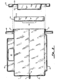
- a microwave oven cavity assembly 10 is formed by a first member 11 being the top portion and a second member 13 being the bottom portion, which have been joined together.
- the top portion 11 is a generally pan-shaped unitary piece having a peripheral edge 12.
- the top portion 11 is formed from a suitable material, such as cold rolled steel, preferably by drawing. Included as part of the top portion 11 is an energy distribution chamber 15 which, as shown in Figure 1, is drawn as an integral part. While this is the preferred construction, it would be possible to provide an opening in the top wall of the first member 11 and attach the energy distribution chamber 15 separately by welding or crimping techniques.
- the lower portion 13 is similarly a unitary drawn part having integrally molded therein the lower well 16.
- the lower well 16 serves as the electrical bottom of the oven cooking cavity. In use a glass or other microwave permeable material in the form of a shelf will be laid on top of the well 16 for cooking purposes.
- Lower portion 13 includes a peripheral edge 14.
- the upper and lower portions are brought into contact along their respective peripheral edges 12 and 14.
- the two halves are then assembled together by crimping one peripheral edge about the other.
- a variety of known crimping techniques can be employed to form the seam such as rolling or crimping.
- the crimp consists of peripheral edge 12 being rolled around peripheral edge 14 in a U shape. However other shapes can be used which would involve deforming both peripheral edge 12 and peripheral edge 14.
- a front panel 18 having an opening corresponding in dimension and shape to the front opening formed by the upper and lower portions of the cavity is slipped on to the front of the cavity in a collar like fashion.
- the front panel 18 includes a forwardly facing flange 21.
- the energy distribution chamber 15 is provided with an aperture 22 for receiving a waveguide 20 through which microwave energy may be transmitted to the energy distributing chamber 15.
- a microwave oven door suitable for use with the described cavity structure consists of an outer portion 30 and an inner portion 31.
- Each of these pieces 30 and 31 can be formed in a single pressing operation, with the inner portion 31 being thereafter attached to the outer portion 30 by welding or other suitable fastening technique.
- Perforations 32 are made in the central portion of the inner piece 31 in order to provide a viewing screen through the oven door.
- a quarter wave choke chamber is formed in the door by horizontal surface 33 and vertical surfuce 35 of outer door portion 30 and by horizontal flange 34 and vertical wall 36 of inner door portion 31.
- Quarter wave chokes of this type are well known in the art and need not be further described at this point.
- the parts illustrated in the drawings consist of the basic structural portions of the microwave oven cavity and door assembly.
- the completed microwave oven would include electrical and mechanical operating parts as well as a decorative outer wrap, and an esthetically pleasing outer door cover. Since these portions do not constitute part of the present invention they are not illustrated in the drawings.
- the microwave oven cavity assembly illustrated and described provides an assembly which is economical to manufacture in that the use of structural welds have been eliminated.
- the assembly derives its structural integrity from the crimped seams found around the peripheral edges of the top and bottom portions of the cavity and around the front peripheral edge between the cavity and the front panel.
- These crimped seams, the first running in a generally horizontal plane and the second running in a generally vertical plane provide a structurally sound apparatus.
- the top and bottom portions of the cavity are drawn, the top portion can include an integral energy distributing chamber as part of the draw tooling, and the lower half can include a cavity bottom well as an integral part of the draw tooling. This precludes the need to form either of the parts in a separate operation or to add them by welding.
- the use of the crimp seam to attach the front panel to the cavity provides the additional advantage of the forwardly protruding flange to mate with the door choke to provide a reliable inserted choke type of construction.
Landscapes
- Physics & Mathematics (AREA)
- Electromagnetism (AREA)
- Engineering & Computer Science (AREA)
- Chemical & Material Sciences (AREA)
- Combustion & Propulsion (AREA)
- Mechanical Engineering (AREA)
- General Engineering & Computer Science (AREA)
- Electric Ovens (AREA)
Claims (5)
Applications Claiming Priority (2)
| Application Number | Priority Date | Filing Date | Title |
|---|---|---|---|
| US06/387,723 US4563560A (en) | 1982-06-11 | 1982-06-11 | Microwave oven construction |
| US387723 | 1982-06-11 |
Publications (3)
| Publication Number | Publication Date |
|---|---|
| EP0096874A2 EP0096874A2 (de) | 1983-12-28 |
| EP0096874A3 EP0096874A3 (en) | 1984-04-25 |
| EP0096874B1 true EP0096874B1 (de) | 1986-10-01 |
Family
ID=23531115
Family Applications (1)
| Application Number | Title | Priority Date | Filing Date |
|---|---|---|---|
| EP83105724A Expired EP0096874B1 (de) | 1982-06-11 | 1983-06-10 | Gehäuse für Mikrowellenherd |
Country Status (6)
| Country | Link |
|---|---|
| US (1) | US4563560A (de) |
| EP (1) | EP0096874B1 (de) |
| AU (1) | AU554343B2 (de) |
| CA (1) | CA1203853A (de) |
| DE (2) | DE96874T1 (de) |
| ZA (1) | ZA834007B (de) |
Cited By (1)
| Publication number | Priority date | Publication date | Assignee | Title |
|---|---|---|---|---|
| DE10314500A1 (de) * | 2003-03-31 | 2004-10-21 | BSH Bosch und Siemens Hausgeräte GmbH | Gargerätemuffel |
Families Citing this family (5)
| Publication number | Priority date | Publication date | Assignee | Title |
|---|---|---|---|---|
| JPS61156280A (ja) * | 1984-12-28 | 1986-07-15 | 株式会社東芝 | デイスプレイモニタ内蔵電子機器収納筐体 |
| US4711982A (en) * | 1986-05-30 | 1987-12-08 | Litton Systems, Inc. | Plastic microwave oven door |
| JPH074405Y2 (ja) * | 1989-04-25 | 1995-02-01 | シャープ株式会社 | 加熱調理器の枠体構造 |
| US6681665B2 (en) * | 1998-02-25 | 2004-01-27 | Stuart Calwell | Aroma therapy delivery system |
| KR102898725B1 (ko) * | 2020-05-11 | 2025-12-12 | 엘지전자 주식회사 | 다중 쵸크를 구비하는 오븐 |
Family Cites Families (8)
| Publication number | Priority date | Publication date | Assignee | Title |
|---|---|---|---|---|
| US1492909A (en) * | 1922-06-29 | 1924-05-06 | Herbert K Olmsted | Range body |
| US1815312A (en) * | 1928-07-05 | 1931-07-21 | Roscoe S Heise | Oven construction |
| US2557496A (en) * | 1944-10-14 | 1951-06-19 | American Stove Co | Range |
| GB909009A (en) * | 1959-12-08 | 1962-10-24 | Radyne Ltd | Improvements in or relating to electrical screening arrangements |
| US3484573A (en) * | 1968-08-08 | 1969-12-16 | Roper Corp Geo D | Closure for microwave oven |
| US3544751A (en) * | 1969-02-04 | 1970-12-01 | Litton Precision Prod Inc | Microwave oven having meshing microwave door seal |
| DE7441834U (de) * | 1974-12-16 | 1976-06-16 | Bosch-Siemens Hausgeraete Gmbh, 7000 Stuttgart | Eile zur herstellung von garbehaeltern, insbesondere von back- und bratrohren |
| CA1184458A (en) * | 1981-06-16 | 1985-03-26 | Noboru Igarashi | Construction of heating compartment for cooking apparatus |
-
1982
- 1982-06-11 US US06/387,723 patent/US4563560A/en not_active Expired - Lifetime
-
1983
- 1983-06-02 ZA ZA834007A patent/ZA834007B/xx unknown
- 1983-06-03 AU AU15362/83A patent/AU554343B2/en not_active Ceased
- 1983-06-10 EP EP83105724A patent/EP0096874B1/de not_active Expired
- 1983-06-10 CA CA000430144A patent/CA1203853A/en not_active Expired
- 1983-06-10 DE DE198383105724T patent/DE96874T1/de active Pending
- 1983-06-10 DE DE8383105724T patent/DE3366567D1/de not_active Expired
Cited By (3)
| Publication number | Priority date | Publication date | Assignee | Title |
|---|---|---|---|---|
| DE10314500A1 (de) * | 2003-03-31 | 2004-10-21 | BSH Bosch und Siemens Hausgeräte GmbH | Gargerätemuffel |
| DE10314500B4 (de) * | 2003-03-31 | 2017-02-09 | BSH Hausgeräte GmbH | Gargerätemuffel |
| DE10314500C5 (de) * | 2003-03-31 | 2020-06-04 | BSH Hausgeräte GmbH | Gargerätemuffel |
Also Published As
| Publication number | Publication date |
|---|---|
| AU554343B2 (en) | 1986-08-14 |
| EP0096874A2 (de) | 1983-12-28 |
| US4563560A (en) | 1986-01-07 |
| AU1536283A (en) | 1983-12-15 |
| EP0096874A3 (en) | 1984-04-25 |
| DE96874T1 (de) | 1984-04-26 |
| CA1203853A (en) | 1986-04-29 |
| ZA834007B (en) | 1985-01-30 |
| DE3366567D1 (en) | 1986-11-06 |
Similar Documents
| Publication | Publication Date | Title |
|---|---|---|
| US4788395A (en) | Configuration for joining components of a microwave oven | |
| US4597374A (en) | Construction of a heating compartment for cooking apparatus | |
| EP0096874B1 (de) | Gehäuse für Mikrowellenherd | |
| EP1023562B1 (de) | Wärmeisolierendes gehäuse | |
| JPS6224592A (ja) | マイクロ波オ−プン用キヤビテイ構造体 | |
| US4547943A (en) | Method of manufacturing a heat exchanger and plate assembly | |
| US5329086A (en) | Waveguide for microwave ovens | |
| US5017750A (en) | Frame construction for microwave oven having an integrally formed open chassis and an inserting opening | |
| US3711673A (en) | Doors for electronic ovens | |
| CA1203580A (en) | Microwave oven with common wrap and cavity walls | |
| EP0251782A1 (de) | Verbindungen für Gehäuse von Haushaltsgeräten und solche Gehäuse | |
| EP0606513A1 (de) | Verfahren zum Herstellen eines Raumes, insbesondere für Lebensmittelbehandlung, und Raum hergestellt nach dem Verfahren | |
| JPS59119118A (ja) | 調理機器の内箱 | |
| KR860002502Y1 (ko) | 마이크로 웨이브 오븐 구조 | |
| JPS646395Y2 (de) | ||
| JPS6136083Y2 (de) | ||
| JPH0212486Y2 (de) | ||
| JPS6236235Y2 (de) | ||
| GB2298113A (en) | Microwave ovens | |
| JPH033861B2 (de) | ||
| JPS6136093Y2 (de) | ||
| JPH0138421Y2 (de) | ||
| JPS59147936A (ja) | 高周波加熱装置の開閉扉の加工方法 | |
| JPH0612175B2 (ja) | 高周波加熱装置 | |
| JPH0241159B2 (de) |
Legal Events
| Date | Code | Title | Description |
|---|---|---|---|
| PUAI | Public reference made under article 153(3) epc to a published international application that has entered the european phase |
Free format text: ORIGINAL CODE: 0009012 |
|
| AK | Designated contracting states |
Designated state(s): DE FR GB IT SE |
|
| ITCL | It: translation for ep claims filed |
Representative=s name: SOCIETA' ITALIANA BREVETTI S.P.A. |
|
| PUAL | Search report despatched |
Free format text: ORIGINAL CODE: 0009013 |
|
| EL | Fr: translation of claims filed | ||
| AK | Designated contracting states |
Designated state(s): DE FR GB IT SE |
|
| DET | De: translation of patent claims | ||
| RHK1 | Main classification (correction) |
Ipc: F24C 15/08 |
|
| 17P | Request for examination filed |
Effective date: 19841024 |
|
| GRAA | (expected) grant |
Free format text: ORIGINAL CODE: 0009210 |
|
| AK | Designated contracting states |
Kind code of ref document: B1 Designated state(s): DE FR GB IT SE |
|
| REF | Corresponds to: |
Ref document number: 3366567 Country of ref document: DE Date of ref document: 19861106 |
|
| ITF | It: translation for a ep patent filed | ||
| ET | Fr: translation filed | ||
| PLBE | No opposition filed within time limit |
Free format text: ORIGINAL CODE: 0009261 |
|
| STAA | Information on the status of an ep patent application or granted ep patent |
Free format text: STATUS: NO OPPOSITION FILED WITHIN TIME LIMIT |
|
| 26N | No opposition filed | ||
| ITTA | It: last paid annual fee | ||
| PGFP | Annual fee paid to national office [announced via postgrant information from national office to epo] |
Ref country code: FR Payment date: 19930316 Year of fee payment: 11 |
|
| PGFP | Annual fee paid to national office [announced via postgrant information from national office to epo] |
Ref country code: SE Payment date: 19930318 Year of fee payment: 11 |
|
| PGFP | Annual fee paid to national office [announced via postgrant information from national office to epo] |
Ref country code: GB Payment date: 19930322 Year of fee payment: 11 |
|
| PGFP | Annual fee paid to national office [announced via postgrant information from national office to epo] |
Ref country code: DE Payment date: 19930630 Year of fee payment: 11 |
|
| PG25 | Lapsed in a contracting state [announced via postgrant information from national office to epo] |
Ref country code: GB Effective date: 19940610 |
|
| PG25 | Lapsed in a contracting state [announced via postgrant information from national office to epo] |
Ref country code: SE Effective date: 19940611 |
|
| EUG | Se: european patent has lapsed |
Ref document number: 83105724.5 Effective date: 19950110 |
|
| GBPC | Gb: european patent ceased through non-payment of renewal fee |
Effective date: 19940610 |
|
| PG25 | Lapsed in a contracting state [announced via postgrant information from national office to epo] |
Ref country code: FR Effective date: 19950228 |
|
| PG25 | Lapsed in a contracting state [announced via postgrant information from national office to epo] |
Ref country code: DE Effective date: 19950301 |
|
| EUG | Se: european patent has lapsed |
Ref document number: 83105724.5 |
|
| REG | Reference to a national code |
Ref country code: FR Ref legal event code: ST |