EP0097321B1 - Relais de protection avec suppression de seconde harmonique - Google Patents
Relais de protection avec suppression de seconde harmonique Download PDFInfo
- Publication number
- EP0097321B1 EP0097321B1 EP83105846A EP83105846A EP0097321B1 EP 0097321 B1 EP0097321 B1 EP 0097321B1 EP 83105846 A EP83105846 A EP 83105846A EP 83105846 A EP83105846 A EP 83105846A EP 0097321 B1 EP0097321 B1 EP 0097321B1
- Authority
- EP
- European Patent Office
- Prior art keywords
- circuit
- output
- differential
- harmonic
- protective relay
- Prior art date
- Legal status (The legal status is an assumption and is not a legal conclusion. Google has not performed a legal analysis and makes no representation as to the accuracy of the status listed.)
- Expired
Links
Images


Classifications
-
- H—ELECTRICITY
- H02—GENERATION; CONVERSION OR DISTRIBUTION OF ELECTRIC POWER
- H02H—EMERGENCY PROTECTIVE CIRCUIT ARRANGEMENTS
- H02H7/00—Emergency protective circuit arrangements specially adapted for specific types of electric machines or apparatus or for sectionalised protection of cable or line systems, and effecting automatic switching in the event of an undesired change from normal working conditions
- H02H7/04—Emergency protective circuit arrangements specially adapted for specific types of electric machines or apparatus or for sectionalised protection of cable or line systems, and effecting automatic switching in the event of an undesired change from normal working conditions for transformers
- H02H7/045—Differential protection of transformers
Definitions
- the present invention relates to a protective relay with second harmonic suppression comprising:
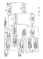
- Fig. 1 is a block diagram of a conventional relay of this known heretofore, wherein there are shown a suppression input terminal 1; a differential input terminal 2; a suppression circuit 3; a differential circuit 4; a first comparator circuit 5; a ratio differential element 6 consisting of the said suppression circuit 3, differential circuit 4 and first comparator circuit 5; a fundamental-wave extraction circuit 7; a second-harmonic extraction circuit 8; a second comparator circuit 9; a second-harmonic detection element 10 consisting of the said fundamental-wave extraction circuit 7, second-harmonic extraction circuit 8 and second comparator circuit 9; an AND circuit 11 which serves to provide the output of the ratio differential element 6 only when the output of the second-harmonic detection element 10 is not received; and an output terminal 12.
- a differential input 11 an output a of the ratio differential element 6, a fundamental wave 12 in thedifferen- tial input, a second harmonic 13 in the differential input, an output b of the second-harmonic detection element, and a final output c.
- the respective waveforms thereof are illustrated in Figs. 2 and 3, wherein the amounts of AC components are represented by dotted lines while the amounts of rectified current components are represented by solid lines.
- the waveform chart of Fig. 2 relates to an exemplary case where an inrush current of a transformer flows as a differential input.
- An inrush current generated upon energization of the transformer without any load is not a fault current, so that the protective relay associated therewith should not function in response to such an inrush current.
- Since a considerable amount of second harmonic component is normally contained in the inrush current, it is generally customary to employ a system of suppressing the output by detecting the content of the second harmonic component.
- the device of Fig. 1 also adopts such output suppression system. As illustrated in Fig.
- the output a of the ratio differential element 6 is active when the differential input is above a predetermined value, while the output b of the second-harmonic detection element 10 is active when the ratio between the second harmonic 13 and the fundamental wave 12 is high. Therefore, the output c of the AND circuit 11 is not provided due to the fact that the output condition of the AND circuit 11 is not satisfied because of the presence of the output b, although the output c rises as represented by a dotted line in case the output b is absent.
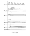
- the waveform chart of Fig. 3 relates to another exemplary case where a differential current is generated as a result of an internal fault, showing that a fundamental wave 12 is generated when a fundamental-frequency current flows as a differential current 11 at time t1.
- the fundamental wave 12 is delayed in its rise due to a filter employed in the fundamental-wave extraction circuit 7 and therefore increases gradually as illustrated.
- the second harmonic output 13 is not to be generated.
- the second-harmonic extraction circuit 8 also incorporates a filter whose characteristic is usually more acute than that of the fundamental-wave extraction circuit 7, the output 13 comes to present steep increase and gradual decrease eventually because of the transient phenomenon derived from the input variation.
- the protective relay according to the present invention is characterized by a monostable multivibrator circuit operating in response to any amount of said differential current in excess of the predetermined value and producing an output signal for a preset period of time; a first logic circuit receptive of, as two inputs thereto, both the output of said monostable multivibrator circuit and the output of said second-harmonic detection element, and producing an output signal therefrom when said two inputs are received simultaneously; a timing circuit for clocking the output duration of said second-harmonic detection element and producing a signal when said output duration reaches a predetermined period of time; a second logic circuit receptive of, as two inputs thereto, both the output of said timing circuit and the output of said first logic circuit, and producing a second-harmonic suppression signal therefrom when at least one of said two inputs is received; and a third logic circuit receptive to, as two inputs thereto, both the second-harmonic suppression signal of said second logic circuit and the output of said ratio differential element, and serving to suppress
- a suppression input terminal 1 a differential input terminal 2, a suppression circuit 3, a differential circuit 4, a first comparator circuit 5, a ratio differential element 6, a fundamental-wave extraction circuit 7, a second-harmonic extraction circuit 8, a second comparator circuit 9, a second-harmonic detection circuit 10, an AND circuit 11, and an output terminal 12. Since such components are basically equal in both structure and function to those shown previously in Fig. 1, the corresponding parts are represented by the same reference numerals, and detailed description therefor is omitted here.
- a differential detection circuit 13 connected to the output terminal of the differential circuit 4 and serving to detect the amount of a differential currentfromthe output of the differential circuit 4; a monostable multivibrator 14 inverted in response to the output of the differential circuit 4 and reset, after being held in the inverted state for a predetermined period of time, to the former state thereof while sending its output during such inverted state; a two-input AND circuit 15 receptive of the outputs of the monostable multivibrator 14 and the second comparison circuit 9fed thereto; a timing circuit 16 having a function of sending its output when the output of the comparison circuit 9 continues for more than a preset period of time; and an OR circuit 17 to which the outputs of both the AND circuit 15 and the timing circuit 16 arefed.
- the AND circuit 11 receives the respective outputs of the OR circuit 17 and the first comparison circuit 5, and sends its output to the terminal 12 when the logical sum condition is satisfied with respect to the two outputs received.
- Figs. 5 and 6 illustrate the waveforms of signals denoted by 11, 12, 13 and a through g in Fig. 4.
- the waveforms a and b are equal to those mentioned previously in connection with Fig. 3.
- the output d of the differential detection circuit 13 is sent to actuate the monostable multivibrator 14, which then produces its output e for a predetermined period of time so that the second AND circuit 15 provides an outputfto suppress the outputb of the second-harmonic detection element 10.
- the output c of the first AND circuit 11 is produced with a time delay in the same manner as explained previously in connection with Fig. 3.
- the timing circuit 16 sends no output at all since the output duration of the second-harmonic detection element 10 has not reached the predetermined time period T.
- the output d of the differential detection circuit 13 is produced continuously since the operating zone of this circuit is generally wider than that of the ratio differential element 6, so that the monostable multivibrator 14sends no output at all and thereby prohibits rise of the output f of the second AND circuit 15. Consequently, differing from the foregoing case of Fig. 3, the output b of the second-harmonic detection element 10 fails to become a signal which suppresses the output of the first AND circuit 11.
- the timing circuit 16 serves to clock the output b of the second-harmonic detection element 10 but does not send its output g as the duration of the output b has not reached the predetermined time period T.
- the output c of the first AND circuit 11 is not interrupted at or immediately after time t2.
- the output a of the ratio differential element 6 and the output b of the second-harmonic detection element 10 are the same as those described in connection with Fig. 2.
- the differential detection circuit 13 produces an output d, so that the monostable multivibrator 14 sends its pulse output e of a fixed width.
- the second AND circuit 15 takes a logical product of the output b of the second-harmonic detection element 10 and the output e of the monostable multivibrator 14 to produce an output f which suppresses the output of the first AND circuit 11.
- the output c of the first AND circuit 11 is on the verge of rising as represented by a dotted line in conformity with the fall of the output f but is actually prohibited from rising by the output g of the timing circuit 16 which clocks the output duration of the second-harmonic detection element 10 and sends such output g after the lapse of a predetermined time period T.
- the output c of the first AND circuit 11 is on the verge of rising as represented by a dotted line in conformity with the fall of the output f but is actually prohibited from rising by the output g of the timing circuit 16 which clocks the output duration of the second-harmonic detection element 10 and sends such output g after the lapse of a predetermined time period T.
- the clock time period T of the timing circuit 16 It is necessary to set the clock time period T of the timing circuit 16 to a proper value longer than the output duration of the second-harmonic detection element 10 (determined by the circuit constant of the element 10 and the amount of an input variation) in the case of any sudden reduction of the differential input but shorter than the output pulse width of the monostable multivibrator 14.
- the time period T is settable to any desired length if the said output pulse width of the monostable multivibrator 14 is longerthan the outputduration of the second-harmonic detection element 10 at the sudden occurrence of a reduction in the differential input.
- Fig. 7 showing a block diagram of another exemplary protective relay with second harmonic suppression embodying the present invention
- the components corresponding or equivalent to those in Fig. 4 are represented by the same reference numerals.
- the differential detection circuit 13 employed in the foregoing example of Fig. 4 is omitted, and the monostable multivibrator 14 is furnished with the output signal a of the first comparison circuit 5.
- Fig. 8 which illustrates the waveforms of signals obtained in the individual parts of the relay
- the ratio differential element produces an outputato actuate the monstable multivibrator 14, which then sends its output e for a predetermined period of time.
- the logical product condition is satisfied with respect to the output e of the monostable multivibrator 14 and the output b of the second-harmonic detection element 9, so thatthe AND circuit 15 comes to send its output f. Consequently, as in the foregoing example shown in Fig. 3, the output c of the AND circuit 11 is sent with a predetermined delay from timet1.
- the timing circuit 16 is prohibited from providing its output since the output b of the second-harmonic detection element 10 has a duration shorter than the preset time period T.
- the output a thereof is sent continuously so that no output is produced from the monostable multivibrator 14. Accordingly, the output f of the AND circuit 15 is not induced to rise and, differing from the foregoing case of Fig. 3, the output b of the second-harmonic detection element 10 does not serve to suppress the output of the AND circuit 11.
- the timing circuit 15 clocks the duration of the output b, its outputg is not sent due to the fact that the clocked duration is shorter than the preset time period T. As a result, there occurs no interruption in the outputcofthe AND circuit 11 at time t2.
- the output a of the ratio differential element 6 and the output b of the second-harmonic detection element 10 have waveforms of Fig. 9 which are the same as those illustrated in Fig. 2. Therefore, the monostable multivibrator 14 sends its pulse output e of a fixed width simultaneously with generation of the output a, so that the AND circuit 15 produces an output fand feeds the same via the OR circuit 17 to the AND circuit 11, thereby prohibiting transmission of the output c.
- the second-harmonic detection element employed in the above embodiments is constituted of a fundamental-wave extraction circuit and a second-harmonic extraction circuit, it is to be understood that the constitution thereof is not limited to the example alone. Furthermore, in addition to the ratio differential relay with second harmonic suppression mentioned above, similar effect is also attainable when this invention is applied to a second harmonic detection type which is used for locking another relay through detection of a second harmonic component. As described hereinabove, according to the present invention which is so composed as to clock and render effectual the output of the second-harmonic detection element only at the time of increase of the differential amount, it becomes possible to achieve remarkable advantages of enhancing the stability of the protective relay and ensuring high operational reliability thereof.
Landscapes
- Engineering & Computer Science (AREA)
- Power Engineering (AREA)
- Protection Of Transformers (AREA)
- Emergency Protection Circuit Devices (AREA)
Claims (8)
caractérisé par:
Applications Claiming Priority (4)
| Application Number | Priority Date | Filing Date | Title |
|---|---|---|---|
| JP10920682A JPS58224518A (ja) | 1982-06-23 | 1982-06-23 | 第2高調波抑制付保護継電器 |
| JP109205/82 | 1982-06-23 | ||
| JP109206/82 | 1982-06-23 | ||
| JP10920582A JPS58224517A (ja) | 1982-06-23 | 1982-06-23 | 第2高調波抑制付保護継電器 |
Publications (3)
| Publication Number | Publication Date |
|---|---|
| EP0097321A2 EP0097321A2 (fr) | 1984-01-04 |
| EP0097321A3 EP0097321A3 (en) | 1985-08-14 |
| EP0097321B1 true EP0097321B1 (fr) | 1987-11-25 |
Family
ID=26448998
Family Applications (1)
| Application Number | Title | Priority Date | Filing Date |
|---|---|---|---|
| EP83105846A Expired EP0097321B1 (fr) | 1982-06-23 | 1983-06-15 | Relais de protection avec suppression de seconde harmonique |
Country Status (5)
| Country | Link |
|---|---|
| US (1) | US4477854A (fr) |
| EP (1) | EP0097321B1 (fr) |
| AU (1) | AU560683B2 (fr) |
| CA (1) | CA1195392A (fr) |
| DE (1) | DE3374742D1 (fr) |
Families Citing this family (11)
| Publication number | Priority date | Publication date | Assignee | Title |
|---|---|---|---|---|
| JPS6110911A (ja) * | 1984-06-27 | 1986-01-18 | 三菱電機株式会社 | 変圧器保護継電器 |
| US4903160A (en) * | 1985-02-25 | 1990-02-20 | Westinghouse Electric Corp. | Sudden, pressure relay supervisory apparatus |
| US4704653A (en) * | 1985-12-10 | 1987-11-03 | Westinghouse Electric Corp. | Transformer differential relay with speed-up apparatus |
| US4873602A (en) * | 1987-11-12 | 1989-10-10 | General Electric Company | Ripple attenuator for AC power transmission line protective relays |
| US5014153A (en) * | 1989-02-01 | 1991-05-07 | Basler Electric Company | Transformer differential relay |
| US4903163A (en) * | 1989-05-09 | 1990-02-20 | The United States Of America As Represented By The Secretary Of The Interior | Directional harmonic overcurrent relay device |
| US5319513A (en) * | 1991-10-17 | 1994-06-07 | Trans-Coil, Inc. | Harmonic monitor and protection module |
| US6208945B1 (en) * | 1997-06-19 | 2001-03-27 | Nissin Electric Co., Ltd. | Harmonic component measuring method for power system |
| US20040264094A1 (en) * | 2003-05-06 | 2004-12-30 | Rahman Md Azizur | Protective control method and apparatus for power devices |
| JP5561831B2 (ja) * | 2010-09-18 | 2014-07-30 | 一般財団法人東北電気保安協会 | 変圧器内部故障検出装置 |
| JP7418245B2 (ja) * | 2020-03-02 | 2024-01-19 | 三菱電機株式会社 | 電流差動リレー装置 |
Family Cites Families (7)
| Publication number | Priority date | Publication date | Assignee | Title |
|---|---|---|---|---|
| SE304325B (fr) * | 1963-11-20 | 1968-09-23 | Asea Ab | |
| DE1257258C2 (de) * | 1963-12-28 | 1973-03-01 | Asea Ab | Transformatordifferentialschutz |
| JPS54142545A (en) * | 1978-04-27 | 1979-11-06 | Toshiba Corp | Ratio differential relay with harmonic suppressor |
| SU698097A1 (ru) * | 1978-05-03 | 1979-11-15 | Горьковское Отделение Ордена Октябрьской Революции Всесоюзного Государственного Проектно-Изыскательского И Научно-Исследовательского Института Энергетических Систем И Электрических Сетей "Энергосетьпроект" | Устройство дл дифференциальной защиты трансформатора |
| US4204237A (en) * | 1978-11-30 | 1980-05-20 | Gould Inc. | Solid state transformer differential relay |
| US4402028A (en) * | 1981-08-17 | 1983-08-30 | Electric Power Research Institute, Inc. | Protective relay methods and apparatus |
| EP0161407B1 (fr) * | 1981-12-29 | 1989-03-08 | Mitsubishi Denki Kabushiki Kaisha | Relais de protection pour réseau de courant fort |
-
1983
- 1983-06-02 AU AU15318/83A patent/AU560683B2/en not_active Ceased
- 1983-06-03 CA CA000429635A patent/CA1195392A/fr not_active Expired
- 1983-06-06 US US06/501,085 patent/US4477854A/en not_active Expired - Lifetime
- 1983-06-15 DE DE8383105846T patent/DE3374742D1/de not_active Expired
- 1983-06-15 EP EP83105846A patent/EP0097321B1/fr not_active Expired
Also Published As
| Publication number | Publication date |
|---|---|
| CA1195392A (fr) | 1985-10-15 |
| AU1531883A (en) | 1984-01-05 |
| US4477854A (en) | 1984-10-16 |
| DE3374742D1 (en) | 1988-01-07 |
| AU560683B2 (en) | 1987-04-16 |
| EP0097321A2 (fr) | 1984-01-04 |
| EP0097321A3 (en) | 1985-08-14 |
Similar Documents
| Publication | Publication Date | Title |
|---|---|---|
| EP0097321B1 (fr) | Relais de protection avec suppression de seconde harmonique | |
| JPS62144535A (ja) | 電力変圧器に用いる差動継電装置 | |
| EP0161403B1 (fr) | Relais de protection pour réseau de courant fort | |
| EP0087700B1 (fr) | Système pour détecter une relation de phase prédéterminée entre deux grandeurs électriques détectées dans un système électrique de puissance | |
| JPS6327925B2 (fr) | ||
| JPS6327926B2 (fr) | ||
| US4562507A (en) | Protective relay | |
| GB2059695A (en) | Overcurrent protection relay | |
| JP3319906B2 (ja) | 欠相保護機能付き遮断器 | |
| JPS60245423A (ja) | 比率差動リレ− | |
| JPH09247845A (ja) | 比率差動継電器 | |
| SU1001280A2 (ru) | Реле дифференциальной защиты шин | |
| JPH0880057A (ja) | 交直変換装置の保護方式 | |
| JP3940492B2 (ja) | ディジタル形保護継電器 | |
| JP2533186B2 (ja) | 励磁突入電流判定方式 | |
| JPH031888B2 (fr) | ||
| JPH0152978B2 (fr) | ||
| JPS58154318A (ja) | 保護継電器 | |
| JPH02188101A (ja) | 電力変換装置 | |
| JPH0210655B2 (fr) | ||
| JPS5935521A (ja) | 後備距離継電装置 | |
| JPS5889020A (ja) | 短時間停電防止装置 | |
| JPS5920260B2 (ja) | 変圧器保護継電装置 | |
| JPS58154317A (ja) | 保護継電器 | |
| JPS6046725A (ja) | 変圧器の差動保護継電装置 |
Legal Events
| Date | Code | Title | Description |
|---|---|---|---|
| PUAI | Public reference made under article 153(3) epc to a published international application that has entered the european phase |
Free format text: ORIGINAL CODE: 0009012 |
|
| AK | Designated contracting states |
Designated state(s): DE GB SE |
|
| PUAL | Search report despatched |
Free format text: ORIGINAL CODE: 0009013 |
|
| AK | Designated contracting states |
Designated state(s): DE GB SE |
|
| 17P | Request for examination filed |
Effective date: 19851015 |
|
| 17Q | First examination report despatched |
Effective date: 19860731 |
|
| GRAA | (expected) grant |
Free format text: ORIGINAL CODE: 0009210 |
|
| AK | Designated contracting states |
Kind code of ref document: B1 Designated state(s): DE GB SE |
|
| REF | Corresponds to: |
Ref document number: 3374742 Country of ref document: DE Date of ref document: 19880107 |
|
| PLBE | No opposition filed within time limit |
Free format text: ORIGINAL CODE: 0009261 |
|
| STAA | Information on the status of an ep patent application or granted ep patent |
Free format text: STATUS: NO OPPOSITION FILED WITHIN TIME LIMIT |
|
| 26N | No opposition filed | ||
| PGFP | Annual fee paid to national office [announced via postgrant information from national office to epo] |
Ref country code: GB Payment date: 19920505 Year of fee payment: 10 |
|
| PGFP | Annual fee paid to national office [announced via postgrant information from national office to epo] |
Ref country code: SE Payment date: 19920615 Year of fee payment: 10 |
|
| PGFP | Annual fee paid to national office [announced via postgrant information from national office to epo] |
Ref country code: DE Payment date: 19920702 Year of fee payment: 10 |
|
| PG25 | Lapsed in a contracting state [announced via postgrant information from national office to epo] |
Ref country code: GB Effective date: 19930615 |
|
| PG25 | Lapsed in a contracting state [announced via postgrant information from national office to epo] |
Ref country code: SE Effective date: 19930616 |
|
| GBPC | Gb: european patent ceased through non-payment of renewal fee |
Effective date: 19930615 |
|
| PG25 | Lapsed in a contracting state [announced via postgrant information from national office to epo] |
Ref country code: DE Effective date: 19940301 |
|
| EUG | Se: european patent has lapsed |
Ref document number: 83105846.6 Effective date: 19940110 |