EP0098519A2 - Dispositif de contrôle du mouvement et de la tenue d'une raquette - Google Patents
Dispositif de contrôle du mouvement et de la tenue d'une raquette Download PDFInfo
- Publication number
- EP0098519A2 EP0098519A2 EP83106339A EP83106339A EP0098519A2 EP 0098519 A2 EP0098519 A2 EP 0098519A2 EP 83106339 A EP83106339 A EP 83106339A EP 83106339 A EP83106339 A EP 83106339A EP 0098519 A2 EP0098519 A2 EP 0098519A2
- Authority
- EP
- European Patent Office
- Prior art keywords
- signal
- racket
- vii
- transmitters
- display
- Prior art date
- Legal status (The legal status is an assumption and is not a legal conclusion. Google has not performed a legal analysis and makes no representation as to the accuracy of the status listed.)
- Pending
Links
Images


Classifications
-
- A—HUMAN NECESSITIES
- A63—SPORTS; GAMES; AMUSEMENTS
- A63B—APPARATUS FOR PHYSICAL TRAINING, GYMNASTICS, SWIMMING, CLIMBING, OR FENCING; BALL GAMES; TRAINING EQUIPMENT
- A63B69/00—Training appliances or apparatus for special sports
- A63B69/38—Training appliances or apparatus for special sports for tennis
Definitions
- the invention relates to a device for controlling the guidance and / or posture of a racket for ball games, in particular for ball games such as tennis, badminton, golf and the like.
- a normal tennis forehand is composed of the following successive phases: taking the basic position, swinging movement, swinging movement and returning to the basic position after the swinging movement has ended, in the course of which the ball is hit. If one of these phases is not carried out or is carried out only incompletely, the blow carried out is usually faulty. However, it is very difficult for the player to gain information as to whether he is handling all of the strokes when handling the racket performed phases perfectly. It is even more difficult to gain information about which of the different stroke phases was carried out incorrectly if the stroke was executed incorrectly.
- the object of the invention is to provide a device for controlling the guidance and / or position of a racket for ball games, which informs the player (or a game teacher) in an easily recognizable form whether the handling of the racket has been carried out correctly.
- a device for controlling the guidance and / or position of a racket for ball games which is characterized by a plurality of signal transmitters, each of which applies a force component which is characteristic of the position of the racket or of the movement of the racket during a game stroke by delivery of a signal responds.
- the signals can be displayed separately or, according to an advantageous embodiment, can be processed into an overall display signal which only informs whether the game hit was carried out without errors or not.
- This overall display signal can be an acoustic or optical signal.
- a short acoustic signal is generated after the end of each game stroke if the game stroke was error-free.
- a short acoustic signal is only generated after the end of each game stroke if a game stroke was performed incorrectly.
- the signals emitted by the various signal transmitters in the course of a game stroke are stored and displayed separately, so that the player can determine which phase of the game stroke was possibly carried out incorrectly on the basis of the signals displayed after the end of a game stroke.
- the memory storing these signals and the corresponding display devices are preferably automatically deleted again before the start of the next game stroke.
- the game strength of the player is included in the evaluation of the various signals emitted by the signal transmitters. Due to the acceleration forces occurring and measured during the execution of a game stroke, the proper time of at least one timing element is set so that it corresponds to the optimal duration of a certain phase of a game stroke.
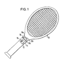
- the device 12 is detachably placed on the handle of the tennis racket 10 shown as an example in FIG. 1 by means of a clip 14 spanning the handle.
- the device 12 is realized in the form of a small and light device, of which only the housing, a switch 16 with four positions and a display field 18 are shown in FIG. 1.
- the switch 16 can be used to set the device to various operating modes, which are explained in detail below.
- the display field 18 serves to display signals which are characteristic of the correct execution of the essential phases of a game stroke. In Fig. 1 three display fields 18a, 18b, 18c are shown as an example.
- the display panel 18a is designed to indicate whether the racket was in the basic position before a game was performed; the display field 18b shows whether the stick position was faultless during the execution of the game stroke; the display panel 18c shows whether the swinging and swinging movement has been carried out correctly and long enough.
- the device is not designed as a separate device releasably placed on the racket, but integrated into the racket, for example built into the handle part thereof.
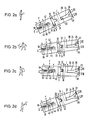
- the device comprises a plurality of signal transmitters I to VII, each of which responds to a force component which is characteristic of the position of the racket or of the movement of the racket in the event of a game stroke by emitting a signal.
- the signal generators I, VI and VII are combined into one unit.
- This unit consists of a mass ball 22, a guide 24 parallel to the longitudinal direction of the housing 20, in which the mass ball 22 is guided so as to be movable in the longitudinal direction, two curved guide sections 26 and 28 which branch off from one end of the straight guide 24, and contact pairs, which can be actuated by the mass ball 22 and are each arranged at a closed end of the guides 24, 26, 28.
- the contact pairs can be, for example, protective gas or so-called reed switches which can be actuated by the mass ball 22 designed as a permanent magnet.
- electromechanical contacts or switches other types of sensors can also be used, for example variable resistors, piezoelectric signal transmitters and the like.
- the signal generators I, VI and VII each emit a signal when the earth ball is at the corresponding end of one of the guides 24, 26, 28.
- the displacement of the mass ball 22 is due to its own weight and the inertia or centrifugal forces that occur during the execution of a game stroke.
- the signal generators III, IV and V are also combined into one unit.
- This unit consists of a guide 30 which is transverse to the longitudinal direction of the housing 20 and a guide 32 for a second mass ball 34 which branches off at right angles from this in the longitudinal direction of the housing 20.
- At the closed ends of the guides 30, 32 are in the same manner as in the previously described Unit contact pairs arranged by the Earth ball 34 can be actuated, these contact pairs and the earth ball can be formed in the same way as in the unit described above.
- the mass ball 34 like the mass ball 22, can be moved by its own weight and by the inertia or centrifugal forces that occur during a stroke, and selectively actuates one of the signal transmitters III, IV and V.
- the signal generator II comprises in a tubular, in the longitudinal direction of the housing 20 a guide 36 a suspended on a tension spring 38 contact mass 40 and a contact 42 arranged opposite this, which is attached to one end of a compression spring 44 which is located at the closed end of the Guide 36 supports.
- the contact mass 40 and the contact 42 are electrically connected via the spring 38 and 44, respectively, to the electrical connections of the signal generator II which are led out of the housing 20.
- the contact mass 40 has a predetermined distance from the contact 42, which is bridged when a sufficient acceleration component acts on the contact mass 40, so that the tension spring 38 is tensioned until the contact mass 40 is in contact with the contact 42.
- the compression spring 44 acts as a damping spring and prevents the contact mass 40 and the contact 42 from being subjected to excessive pressure.
- an electromechanical acceleration converter which in the embodiment shown in FIG. 2 is shown as a potentiometer P, the wiper position of which is determined by the position of the contact mass 40 inside its guide 36.
- the contact mass 44 is thus connected to the wiper of the potentiometer P. If a constant voltage is applied to the two fixed connections of the potentiometer P, a voltage signal can be tapped between one of these connections and the wiper is proportional to the acceleration acting on the contact mass 40.
- This analog voltage signal occurring during a stroke execution is used in a processing circuit to be explained later in order to take the playing strength into account when evaluating the various signals.
- the position of the device shown in FIG. 2a roughly corresponds to the position of the racket in the basic position also shown in FIG. 1, which is also outlined in FIG. 2a.
- the switches of signal generators I and V are closed, while the switches of the other signal generators are open.
- FIG. 3 the timing diagram of FIG. 3, where the times entered on the abscissa correspond to the boundary between the different phases of a complete racket handling cycle, while on the ordinate the switch states of the signal generators I to VII as levels "1" (on) and " 0 "(off) are shown.
- the basic position shown in FIG. 2a corresponds to the time span between times t 0 and t 1 .
- FIG. 2c shows the swing movement in the course of which the ball is to be hit.
- this swing movement which corresponds to the time span t 2 to t 4 in the diagram in FIG. 3, the same forces occur as in the outward movement shown in FIG. 2b, but these forces are greater because the swing movement is of greater intensity than the outward movement is carried out. Therefore, in addition to the switches of signal generators III and VII, the switch of signal generator II is also closed. At the same time, the wiper of the potentiometer P is moved to another position that corresponds to the intensity of the swing movement.
- the ball is hit, for example, at time t 3 , ie approximately in the middle of the time interval between times t 2 and t 4 ' .
- FIG. 2d shows the final phase of the swing movement, which corresponds to the period t 4 to t 5 in FIG. 3.
- this phase essentially the same forces act on the racket or the mass balls 22 and 34 and on the contact mass 40 as in the previous phase shown in FIG. 2c, since these two phases merge directly into one another. Consequently, in this final phase of the game stroke cycle, the states of the various switches of the signal generators correspond to those in the preceding swing phase.
- FIGS. 2a and 2d it is presupposed that the racket is not held vertically but twisted about its longitudinal axis in order to play a slice or cut ball. However, if the racket is held vertically, to play a normal flying ball, the switch of the signal generator V remains closed during the entire game stroke cycle, while the switch of the signal generator III remains open. Otherwise, the different switch states for a normal beat are the same as for a slice beat.
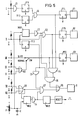
- the digital processing circuit shown in FIG. 5 has signal inputs labeled I to VII, each of which is connected to the corresponding signal generator I to VII. One terminal of each signal input is connected to ground, while the other terminal is connected to a positive potential via a high-level resistor. Depending on the switching state of the switch assigned to a signal transmitter, either a voltage signal with the level zero or a voltage signal with a predetermined positive level is present at the signal inputs I to VII, e.g. +5 V.
- the signal input of the signal generator I is applied on the one hand directly to the set input of a flip-flop FF2 and on the other hand via an inverter I1 to the set input of a flip-flop FF1.
- the Q outputs of flip-flops FF1 and FF2 are applied to the two inputs of an AND circuit G1, the output of which is applied to an input of a NAND circuit G4.
- the output of the AND circuit G1 is connected to the set input of a flip-flop FF4, the Q output of which drives a display device D1, which is, for example, a liquid crystal display acts, which forms one of the display fields 18a to 18c (Fig. 1).
- the display device D1 can, for example, light up or delete a symbol.
- the signal input of the signal generator II is connected on the one hand to the set input of a flip-flop FF3 and on the other hand to an input of an AND circuit G2 and to the control input of a monostable multivibrator MV1, which has an adjustable natural time.
- the output of the monostable multivibrator MV1 is connected to the second input of the AND circuit G2 via an inverter I2.
- the Q output of the flip-flop FF3 is connected to one of three inputs of an AND circuit G5, the second input of which is connected to the output of the inverter I2 and the third input of which is connected to the output of the NAND circuit G4.
- the output of the AND circuit G2 is also connected to one of the three inputs of the NAND circuit G4 and to the set input of a flip-flop FF5.
- the Q output of the flip-flop FF5 drives a display device D2 which e.g. corresponds to the display field 18b (FIG. 1).
- This can also be a liquid crystal display, which is characterized by low power consumption.
- the signal input of the signal generator III is connected via a changeover switch SW to the third input of the NAND circuit G4 and to the set input of a flip-flop FF6, the Q output of which controls a third display device D3 which corresponds to the display field 18c (FIG. 1) can.
- the switch SW is shown in its "slice" position, which corresponds to the game stroke cycle shown in FIGS. 2a to 2d.
- the other position of the switch SW is labeled "normal". This position corresponds to a normal stroke in which the racket is held vertically.
- the changeover switch SW connects the third input of the NAND circuit G4 and the set input of the flip-flop FF6 with the output of an OR circuit G3, one input of which is connected to the signal generator IV and the other input of which is connected to the signal generator V.
- the signal inputs of the signal transmitters VI and VII are applied to the two inputs of a further OR circuit G8, the output of which controls an AND circuit G7 on the one hand and the control input of a monostable multivibrator MV2 on the other hand with adjustable natural time.
- the AND circuit G7 has two further inputs, one of which is connected via an inverter I3 to the Q output of the flip-flop FF3 and the other via an inverter I4 to the output of the monostable multivibrator MV2.
- the outputs of the AND circuits G5 and G7 are connected to the two inputs of an OR circuit G6, the output of which controls an acoustic signal generator B.
- an acoustic signal generator B This can e.g. an electromechanical transducer such as a small speaker, buzzer or piezoelectric transducer.
- an optical signal generator can also be provided, e.g. in the form of a light emitting diode.
- the output of the multivibrator MV2 is also connected via the inverter I4 to the control input of a monostable multivibrator MV3, the output of which controls a circuit called "reset" which, after the natural time of the multivibrator MV3 has expired, emits a short voltage pulse which is sent as a reset signal to the R -Inputs of all flip-flops FF1 to FF6 is created. This will reset these flip-flops.
- the natural time of the monostable multivibrators MV1 and MV2 is set by the voltage signal tapped at the wiper of the potentiometer P, which is integrated, for example, via a phase of the movement sequence, such as is symbolically illustrated by a capacitor C, which connects the wiper of the potentiometer P to ground.
- the flip-flop FF2 is set at the time t, while the flip-flop FF1 is set at the time t 1 by the drop in the signal emitted by the signal generator I. After both flip-flops FF1 and FF2 are set, the AND circuit G1 generates an output signal by which the flip-flop FF4 is set and the display device D1 is activated. This indicates that the "basic position" condition has been met.
- the switches belonging to signal generators III and VII close.
- the signal present at the input of the signal generator III reaches the flip-flop FF6 via the changeover switch SW and sets it, as a result of which the display device D3 is activated. This indicates that the racket is in the correct posture, namely in an oblique position, which is necessary for the execution of a slice hit.
- the signal present at the signal input of the signal generator VII reaches the control input of the multivibrator MV2 via the OR circuit G8 and sets it in its active state.
- the intrinsic time of the multivibrator MV2 determines a specified period of time after leaving the basic position of the racket, within which a complete stroke cycle is to be completed and the racket is to be returned to the basic position.
- This proper time can, for example three seconds, but can be set by the signal of the potentiometer P to a much lower value, for example 1.5 seconds, which corresponds to a higher skill level of the player.
- the switch of signal generator II closes.
- flip-flop FF3 is set and monostable multivibrator MV1 is set to its active state.
- the intrinsic time of the monostable multivibrator MV1 corresponds to a minimum duration of a swing movement, which is required in order to carry out the swing movement with sufficient intensity and long enough.
- the end of this natural time of the monostable multivibrator MV1 corresponds to the time t 4 in FIG. 3.
- the signal generator B should sound a short signal "error" after the completion of a complete impact cycle.
- the switch of the signal generator II opens during the intrinsic time of the multivibrator MV1 because the swing movement is not carried out with sufficient intensity or duration. Then, after the natural time of the multivibrator MV1 has passed, the AND circuit G2 has positive potential at only one input, so that this circuit is locked. As a result, two positive signals and a signal "0" are present at the NAND circuit G4. The circuit therefore generates a positive output signal, so that the AND circuit G5 is turned on, which in turn turns on the OR circuit G6 and the signal generator B is driven.
- the player can use the states of the display devices D1, D2 and D3 to determine which phase of the stroke cycle was faulty.
- the flip-flops FF4, FF5 and FF6 in each case store the signal which indicates whether the relevant phase of the impact cycle was correct or not.
- FIG. 4 Another faulty club handling, which also leads to the error display by the signal generator B, is illustrated in FIG. 4. If the racket basic position is left at time t 1 because, for example, the club head is lowered and switch VI therefore closes, after the idle time of the monostable multivibrator MV2, a positive signal is sent to the AND- by the inverter I4 due to its output signal going to low level. Circuit G7 applied, the other inputs are also at a positive level. Therefore, the OR circuit G6 is turned on and the signal generator B is energized until the reset pulse occurs (t 6 ).
- the flip-flop FF3 is set, and its positive output signal, which is inverted in the inverter circuit I3, blocks the AND circuit G7, so that the signal generator G is not controlled.
- the described embodiment of the digital processing circuit can easily be constructed as an integrated circuit. It can be implemented in MOS technology, for example, and is characterized by the lowest current consumption need out.
- the entire device according to the invention for controlling the guidance and / or posture of a racket for ball games can therefore be constructed compactly, easily and inexpensively.
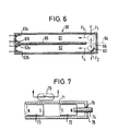
- FIG. 6 shows a special embodiment of a signal transmitter 60 which can simultaneously detect a plurality of force components which are characteristic of the position of the racket in order to execute certain strokes.
- a racket is inclined in its basic position with respect to the vertical in one direction or in the other, the ball will spin after its stroke around its center in one of two opposite directions of rotation.
- Such "effect" shots which can be performed with forehand or backhand, require different basic attitudes of the racket.
- the signal transmitter 60 shown in FIG. 6 contains two mutually parallel guideways 61, 62 for a spherical flyweight 63.
- the two guideways 61, 62 lie on both sides of a plane 64 parallel to the central plane of the racket.
- the plane 64 is contained in a partition wall 65 which delimits the two guideways 61, 62 from one another.
- the two guideways 61, 62 are connected to one another only via a recess 66 in the partition wall 65, the size of which is dimensioned for the free passage of the centrifugal weight 63.
- the recess 66 is located at that end of the partition 65 which corresponds to the ends of the guideways 61, 62 at which the flyweight 63 is located when the racket is in its basic position and at rest. Referring to Figure 6, the recess 66 is on the right side and the plane 64 is approximately vertical for the racket's normal posture.
- contact pairs 61a, 61b and 62a, 62b are arranged, which are electrically connected to one another by simultaneous contact with the spherical flyweight 63;
- the flyweight 63 is coated, for example, with a material that is suitable for good electrical contact.
- the flyweight 63 can be gold-plated, for example, as can the contacts 61a, 61b, 62a and 62b.
- the signal transmitter 60 shown in FIG. 6 can be provided in addition to the signal transmitters explained with reference to FIGS. 2a to 2d or be combined with these.
- the embodiment of the signal transmitter shown in FIG. 7 contains, as a centrifugal weight, a bar magnet 73 which is guided in a longitudinally displaceable manner in a guideway 71. 7 shows only the end section of this guideway 71. At the end of the guideway 71 there is a further bar magnet 72, the magnetic pole orientation of which is opposite to that of the bar magnet 73, so that these magnets repel one another.
- the bar magnet 72 is arranged to be longitudinally displaceable at the end of the guideway 71 and can be locked in the desired position by an adjusting screw 74 accessible from the outside.
- One end of the adjusting screw 74 is anchored in a bore of the bar magnet 72, while its other end in a threaded bore 76 on the end wall 78 of the guide track 71 is screwed in.
- a reed switch 79 which can be actuated by the bar magnet 73, is arranged adjacent to the guideway 71 and at a short distance from its end.
- the magnetic repulsive forces between the bar magnets 72 and 73 act like a compression spring which has a function analogous to that of the spring 38 in FIGS. 2a-2d.
- the momentum of the centrifugal weight at which the switch 79 is to respond can be set as desired by adjusting the longitudinal position of the bar magnet 72 by means of the adjusting screw 74 in accordance with the player's playing strength.
Landscapes
- Health & Medical Sciences (AREA)
- General Health & Medical Sciences (AREA)
- Physical Education & Sports Medicine (AREA)
- Golf Clubs (AREA)
- Heating, Cooling, Or Curing Plastics Or The Like In General (AREA)
Applications Claiming Priority (4)
| Application Number | Priority Date | Filing Date | Title |
|---|---|---|---|
| DE19823225843 DE3225843A1 (de) | 1982-07-09 | 1982-07-09 | Vorrichtung zum kontrollieren der fuehrung und/oder haltung eines schlaegers fuer ballspiele |
| DE3225843 | 1982-07-09 | ||
| DE3316126 | 1983-05-03 | ||
| DE19833316126 DE3316126A1 (de) | 1983-05-03 | 1983-05-03 | Vorrichtung zum kontrollieren der fuehrung und/oder haltung eines schlaegers fuer ballspiele |
Publications (2)
| Publication Number | Publication Date |
|---|---|
| EP0098519A2 true EP0098519A2 (fr) | 1984-01-18 |
| EP0098519A3 EP0098519A3 (en) | 1984-03-21 |
Family
ID=25802962
Family Applications (1)
| Application Number | Title | Priority Date | Filing Date |
|---|---|---|---|
| EP83106339A Pending EP0098519A3 (en) | 1982-07-09 | 1983-06-29 | Device to monitor a racket stroke and grip |
Country Status (8)
| Country | Link |
|---|---|
| EP (1) | EP0098519A3 (fr) |
| AU (1) | AU1634483A (fr) |
| BR (1) | BR8303639A (fr) |
| DK (1) | DK316283A (fr) |
| FI (1) | FI832513L (fr) |
| GR (1) | GR77590B (fr) |
| NO (1) | NO832412L (fr) |
| PT (1) | PT76941B (fr) |
Cited By (5)
| Publication number | Priority date | Publication date | Assignee | Title |
|---|---|---|---|---|
| EP0291621A1 (fr) * | 1987-05-18 | 1988-11-23 | Adolf Brunner | Dispositif pour programmer et contrôler la tenue et le mouvement d'une raquette |
| WO2000043084A1 (fr) * | 1998-01-12 | 2000-07-27 | Eric Ratiarson | Dispositif d'aide a la manipulation d'une raquette, notamment d'une raquette de tennis |
| FR2829700A1 (fr) | 2001-09-19 | 2003-03-21 | Feel Your Play Technology | Article de sport tel qu'une raquette de tennis, comportant au moins un detecteur de mouvement |
| EP1554020A4 (fr) * | 2002-10-03 | 2007-07-25 | Audio Coach Pty Ltd | Capteur amovible utile pour la detection du plan et de la trajectoire du putt |
| DK201570199A1 (en) * | 2015-04-07 | 2016-10-24 | Mdt As | System for counting scores in a sports match |
Family Cites Families (7)
| Publication number | Priority date | Publication date | Assignee | Title |
|---|---|---|---|---|
| US3270564A (en) * | 1964-05-18 | 1966-09-06 | James W Evans | Athletic swing measurement system |
| US3498616A (en) * | 1968-08-19 | 1970-03-03 | Robert D Hurst | Golf swing practice device |
| US3792863A (en) * | 1972-05-30 | 1974-02-19 | Athletic Swing Measurement | Swing measurement system and method employing simultaneous multi-swing display |
| US3762720A (en) * | 1972-08-18 | 1973-10-02 | Raymond Lee Organization Inc | Golf training aid |
| JPS5244139Y2 (fr) * | 1973-05-18 | 1977-10-06 | ||
| US4257594A (en) * | 1975-12-05 | 1981-03-24 | Richard N. Conrey | Electronic athletic equipment |
| FR2513752A1 (fr) * | 1981-09-30 | 1983-04-01 | Richards Camille | Dispositif de signalement d'inclinaison |
-
1983
- 1983-06-27 PT PT76941A patent/PT76941B/pt unknown
- 1983-06-28 AU AU16344/83A patent/AU1634483A/en not_active Abandoned
- 1983-06-29 EP EP83106339A patent/EP0098519A3/de active Pending
- 1983-07-01 NO NO832412A patent/NO832412L/no unknown
- 1983-07-04 GR GR71852A patent/GR77590B/el unknown
- 1983-07-07 BR BR8303639A patent/BR8303639A/pt unknown
- 1983-07-08 DK DK316283A patent/DK316283A/da not_active Application Discontinuation
- 1983-07-08 FI FI832513A patent/FI832513L/fi not_active Application Discontinuation
Cited By (7)
| Publication number | Priority date | Publication date | Assignee | Title |
|---|---|---|---|---|
| EP0291621A1 (fr) * | 1987-05-18 | 1988-11-23 | Adolf Brunner | Dispositif pour programmer et contrôler la tenue et le mouvement d'une raquette |
| WO2000043084A1 (fr) * | 1998-01-12 | 2000-07-27 | Eric Ratiarson | Dispositif d'aide a la manipulation d'une raquette, notamment d'une raquette de tennis |
| FR2829700A1 (fr) | 2001-09-19 | 2003-03-21 | Feel Your Play Technology | Article de sport tel qu'une raquette de tennis, comportant au moins un detecteur de mouvement |
| EP1554020A4 (fr) * | 2002-10-03 | 2007-07-25 | Audio Coach Pty Ltd | Capteur amovible utile pour la detection du plan et de la trajectoire du putt |
| US7331875B2 (en) | 2002-10-03 | 2008-02-19 | Audio Coach Pty Ltd. | Attachable sensor for putting stroke path and plane detection |
| DK201570199A1 (en) * | 2015-04-07 | 2016-10-24 | Mdt As | System for counting scores in a sports match |
| DK179075B1 (en) * | 2015-04-07 | 2017-10-09 | Mdt As | System for counting scores in a sports match |
Also Published As
| Publication number | Publication date |
|---|---|
| NO832412L (no) | 1984-01-10 |
| FI832513A7 (fi) | 1984-01-10 |
| EP0098519A3 (en) | 1984-03-21 |
| PT76941B (de) | 1986-02-03 |
| BR8303639A (pt) | 1984-02-14 |
| DK316283D0 (da) | 1983-07-08 |
| DK316283A (da) | 1984-01-10 |
| AU1634483A (en) | 1984-01-12 |
| GR77590B (fr) | 1984-09-24 |
| FI832513A0 (fi) | 1983-07-08 |
| FI832513L (fi) | 1984-01-10 |
| PT76941A (de) | 1983-07-01 |
Similar Documents
| Publication | Publication Date | Title |
|---|---|---|
| DE3751142T2 (de) | Vorrichtung zum Programmieren und Kontrollieren der Haltung und Führung eines Ballschlägers. | |
| DE69613994T2 (de) | Vorrichtung zur messung mindestens eines parameters eines vorwärts getriebenen spielballs | |
| DE2831383C2 (fr) | ||
| DE3787467T2 (de) | Pneumatische Steuervorrichtung für Spielautomat. | |
| DE68913752T2 (de) | Ein system zum verfolgen von billardbällen. | |
| DE19839799A1 (de) | Versenkbares Ziel für ein Pinball- oder Flipper-Spiel | |
| CH660272A5 (de) | Verfahren zum umkodieren einer folge von datenbits in eine folge von kanalbits. | |
| DE4420472A1 (de) | Lochballspiel | |
| DE19633658A1 (de) | Ballschläger für ein Lochballspiel | |
| EP0074516A2 (fr) | Billard | |
| DE10153557A1 (de) | Elektronisches Pfeilspiel | |
| DE2656082A1 (de) | Tennisschlaeger | |
| DE29907698U1 (de) | An einer Tischtennisplatte anbringbare Ballwurfmaschine für Tischtennis | |
| EP0098519A2 (fr) | Dispositif de contrôle du mouvement et de la tenue d'une raquette | |
| DE3732762A1 (de) | Einrichtung zum wiederauffinden von golfbaellen | |
| DE3436218C2 (fr) | ||
| DE2410174A1 (de) | Verfahren und einrichtung zur bestimmung von richtung und groesse des dralles von spiel-, insbesondere von golfbaellen | |
| DE3225843A1 (de) | Vorrichtung zum kontrollieren der fuehrung und/oder haltung eines schlaegers fuer ballspiele | |
| DE3316126A1 (de) | Vorrichtung zum kontrollieren der fuehrung und/oder haltung eines schlaegers fuer ballspiele | |
| EP0130238A2 (fr) | Dispositif d'entraînement en particulier pour jeux de balle | |
| DE2528784C3 (de) | Elektronische Schaltung zur Erzeugung von Effet-Stößen bei Zeichenanzeigesystemen auf Leuchtschirmen, insbesondere für Leuchtschirmspiele | |
| DE3218854A1 (de) | Schlaeger fuer ballspiele | |
| DE3100183A1 (de) | Spielgeraet, insbesondere zur simulierung eines ballspiels nach art von tennis | |
| DE3414467A1 (de) | Schlagzaehler | |
| DE19816389A1 (de) | Trainingsschläger |
Legal Events
| Date | Code | Title | Description |
|---|---|---|---|
| PUAI | Public reference made under article 153(3) epc to a published international application that has entered the european phase |
Free format text: ORIGINAL CODE: 0009012 |
|
| AK | Designated contracting states |
Designated state(s): AT BE CH DE FR GB IT LI LU NL SE |
|
| PUAL | Search report despatched |
Free format text: ORIGINAL CODE: 0009013 |
|
| AK | Designated contracting states |
Designated state(s): AT BE CH DE FR GB IT LI LU NL SE |
|
| RAP1 | Party data changed (applicant data changed or rights of an application transferred) |
Owner name: ESI ELECTRONIC SPORTS INC. (AG) |
|
| 17P | Request for examination filed |
Effective date: 19840907 |
|
| 17Q | First examination report despatched |
Effective date: 19860723 |
|
| STAA | Information on the status of an ep patent application or granted ep patent |
Free format text: STATUS: EXAMINATION IS IN PROGRESS |
|
| D17Q | First examination report despatched (deleted) | ||
| 19U | Interruption of proceedings before grant |
Effective date: 19850320 |
|
| 19W | Proceedings resumed before grant after interruption of proceedings |
Effective date: 20251201 |
|
| PUAJ | Public notification under rule 129 epc |
Free format text: ORIGINAL CODE: 0009425 |
|
| 32PN | Public notification |
Free format text: MITTEILUNG GEMAESS REGEL 142 EPUE (WIEDERAUFNAHME DES VERFAHRENS NACH REGEL 142 (2) EPUE VOM 24.07.2025) |