EP0130238A2 - Dispositif d'entraînement en particulier pour jeux de balle - Google Patents
Dispositif d'entraînement en particulier pour jeux de balle Download PDFInfo
- Publication number
- EP0130238A2 EP0130238A2 EP83111052A EP83111052A EP0130238A2 EP 0130238 A2 EP0130238 A2 EP 0130238A2 EP 83111052 A EP83111052 A EP 83111052A EP 83111052 A EP83111052 A EP 83111052A EP 0130238 A2 EP0130238 A2 EP 0130238A2
- Authority
- EP
- European Patent Office
- Prior art keywords
- training device
- training
- path
- time
- infrared
- Prior art date
- Legal status (The legal status is an assumption and is not a legal conclusion. Google has not performed a legal analysis and makes no representation as to the accuracy of the status listed.)
- Withdrawn
Links
- 238000012549 training Methods 0.000 title claims abstract description 163
- 238000011156 evaluation Methods 0.000 claims abstract description 58
- 238000012545 processing Methods 0.000 claims abstract description 3
- 230000004888 barrier function Effects 0.000 claims description 9
- 238000006073 displacement reaction Methods 0.000 claims description 5
- 239000000654 additive Substances 0.000 claims description 4
- 230000000996 additive effect Effects 0.000 claims description 4
- 230000006835 compression Effects 0.000 claims description 4
- 238000007906 compression Methods 0.000 claims description 4
- 230000001960 triggered effect Effects 0.000 claims description 3
- 238000003780 insertion Methods 0.000 claims description 2
- 230000037431 insertion Effects 0.000 claims description 2
- 238000000034 method Methods 0.000 claims description 2
- 230000008569 process Effects 0.000 claims description 2
- 241000446313 Lamella Species 0.000 description 10
- 238000006243 chemical reaction Methods 0.000 description 6
- 230000002349 favourable effect Effects 0.000 description 5
- 230000008859 change Effects 0.000 description 3
- 230000003750 conditioning effect Effects 0.000 description 3
- 238000013461 design Methods 0.000 description 3
- 230000006870 function Effects 0.000 description 3
- 230000001965 increasing effect Effects 0.000 description 3
- 230000000712 assembly Effects 0.000 description 2
- 238000000429 assembly Methods 0.000 description 2
- 230000005540 biological transmission Effects 0.000 description 2
- 230000007423 decrease Effects 0.000 description 2
- 238000010586 diagram Methods 0.000 description 2
- 238000005259 measurement Methods 0.000 description 2
- 230000004044 response Effects 0.000 description 2
- 241001295925 Gegenes Species 0.000 description 1
- 238000005452 bending Methods 0.000 description 1
- 230000009286 beneficial effect Effects 0.000 description 1
- 239000002131 composite material Substances 0.000 description 1
- 239000013013 elastic material Substances 0.000 description 1
- 239000004744 fabric Substances 0.000 description 1
- 230000001976 improved effect Effects 0.000 description 1
- 230000001939 inductive effect Effects 0.000 description 1
- 230000009191 jumping Effects 0.000 description 1
- 239000002655 kraft paper Substances 0.000 description 1
- 239000000463 material Substances 0.000 description 1
- 239000004033 plastic Substances 0.000 description 1
- 230000036632 reaction speed Effects 0.000 description 1
- 230000011664 signaling Effects 0.000 description 1
- 210000002023 somite Anatomy 0.000 description 1
- 239000004575 stone Substances 0.000 description 1
- 239000004753 textile Substances 0.000 description 1
- 238000002604 ultrasonography Methods 0.000 description 1
- 238000011144 upstream manufacturing Methods 0.000 description 1
- 239000002023 wood Substances 0.000 description 1
Images


Classifications
-
- A—HUMAN NECESSITIES
- A63—SPORTS; GAMES; AMUSEMENTS
- A63B—APPARATUS FOR PHYSICAL TRAINING, GYMNASTICS, SWIMMING, CLIMBING, OR FENCING; BALL GAMES; TRAINING EQUIPMENT
- A63B69/00—Training appliances or apparatus for special sports
- A63B69/0097—Ball rebound walls
Definitions
- the invention relates to a training device, in particular for ball games.
- Training walls for ball games are known (DE-GM 81 35 417 and European Patent Application No. 82 111 009.5). With training walls, e.g. have marked target points, the reaction speed and the condition of the respective player should be checked and improved by practicing.
- the invention has for its object to develop a training device, in particular for ball games, with which the performance of the user can be determined quantitatively and which, if necessary, by means of signals (optically or acoustically) stimulates to improve his performance.
- position sensors and / or impact force measuring devices which can be actuated when an object strikes an object are arranged at selected target locations on a training wall and are connected to an evaluation circuit with which evaluation numbers assigned to the individual position sensors and / or impact force measuring devices can be processed when actuated by the object and, optionally after additive, subtractive or multiplicative processing with previously obtained evaluation numbers, can be displayed on a display device.
- This training device is particularly suitable for improving the technical skills when playing football or for other ball games.
- Quantitative parameters for assessing the performance of the user are the impact force of the ball on the training wall and the location of the ball impact on the wall. Generally, a ball is easier to place on the center of the training wall than on the outside.
- a hit at the right or left corners of the training wall can be rated higher than a hit in the central region of the training wall.
- Another measure of performance is the energy that is supplied to the ball.
- the energy of the ball can be determined from the impact force on the training wall. There is a particularly high level of performance when the ball hits the wall off-center, in particular in the area of the corners, with great force.
- the target points are preferably embodied in the training wall as pivotably mounted hit flaps.
- the hit flaps also represent marked target points, the on different locations on the training wall can be arranged. By deflecting the hit flap touched by the ball, an exact and unambiguous determination of the impact location is possible.
- the position sensors are designed as switching elements which can be actuated by the hit flaps during the deflection.
- the position sensors are thus permanently assigned to the respective hit flap.
- Different assessment figures correspond to the individual position indicators. It is also possible to assign the same valuation numbers to different position providers. For example, position sensors that are the same distance from the center of the training wall but are on different sides of the center can receive the same evaluation numbers.
- the impact force measuring devices are preferably springs connected to the hit flaps and switch elements which can be actuated as a function of the compression of the springs.
- the switching elements for determining the impact force of the ball are expediently also position sensors.
- Several switching elements, which are actuated by a hit flap depending on their deflection, can be assigned the same position value but different values for the impact force.
- a composite evaluation number can be generated from the position value and the different force values, which is different for the individual switching elements of the same hit flap.
- Photoelectric, capacitive, piezoelectric or inductive switches can be used as switching elements. It is also possible to use mechanical switches, e.g. Limit switch to use.
- the switching elements are expediently arranged at the same level with respect to the hit flaps and can be switched on by the hit flaps using actuators of different lengths. It is also expedient if the switching elements are arranged at different levels with respect to the hit flaps and can be switched on by the hit flaps by actuating members of approximately the same length.
- the arrangements explained above are characterized by their simple structure and can be installed and adjusted quickly and with a few simple steps.
- the hit flaps preferably each contain an actuating member with switching cams, along the displacement path of which the switching elements are arranged. As a result, the number of actuators can be reduced.
- a switching element which can be actuated when the extent of a spring is changed is provided, the actuation duration of which is measured as a variable proportional to the impact force.
- Low impact forces cause only a small change in the spring length.
- the spring therefore returns to its original position after a short time. Larger impact forces change the extension of the spring more. It takes a long time for the spring to return to its original position.
- the actuation duration of the switching element is therefore a measure of the impact force of the ball.
- the position sensors are assigned the higher the evaluation numbers, the further they are from the center of the training wall, while the impact force measuring devices are assigned evaluation numbers corresponding to the level of the impact force.
- This setting provides readings that provide an accurate value for the skills of handling the ball.
- the hit flaps are trapezoidal and taper in the direction of the edges of the training wall.
- the trapezoidal hit flaps can radiate from the center.
- These hit flaps are articulated on their narrow sides facing the center or the edges of the training wall.
- Position sensors and force measuring devices are expediently arranged along the hit flaps.
- the hit flaps can also be used e.g. B. for tennis across the training wall in different widths.
- the evaluation circuit has a triggerable, presettable time measuring device which can be reset when a position sensor and / or an impact force measuring device is actuated or after the preset time has elapsed.
- a time limit can be specified within which a ball must hit the training wall. The time it takes to shoot the ball onto the training wall is also a measure of the skill in handling the ball.
- the time determined by the time measuring device upon actuation of a position sensor or a force measuring device is processed and displayed additively, subactively or multiplicatively with the evaluation numbers for the position and the impact force.
- the number obtained in this way makes it possible to quickly and easily determine the changes in the skill in handling the ball that occur during continuous training of the user. With different users, the different skills can be recorded one after the other and displayed at the same time.
- the training wall can also have a central section and two outer sections inclined at an angle to this section. This embodiment is also particularly stable and stable.
- the training wall can be moved in the horizontal direction against the force of springs arranged at the four corners, switching elements being arranged along the displacement paths of the corners, which can be actuated as a function of the position of the corners. Depending on the point of impact of the ball, the corners are shifted more or less against the force of the springs. The impact force is measured in two steps using the two switching elements.
- the embodiment is characterized by a particularly simple structure.
- the training wall is pivotally mounted about its central vertical or horizontal axis, that the training wall is held in its rest position with two springs arranged on both sides of the axis and that switching elements can be actuated when the training wall is pivoted. In this embodiment, there is no rating if the training wall is hit in the middle.
- the energy supply to the switching elements is preferably switched off after the time period preset in the time measuring device has expired. If the preset time is exceeded, the training device no longer outputs evaluation numbers.
- the preset time is intended to prevent that an unnecessarily large amount of time is used to prepare the ball shot.
- Another favorable embodiment consists in that the energy supply to the switching elements can be switched off after the time period set in a time switch which can be actuated by coin insertion.
- the training device is only available against payment of the playing time.
- Another preferred embodiment includes a display device with at least two digital displays for the resulting evaluation numbers of two users and a digital display connected to the time measuring device.
- the resulting evaluation numbers resulting from one or more attempts to play by two users can be compared directly with one another.
- the two numerical displays for the resulting evaluation numbers are preferably assigned display elements as a reference to the players.
- the displays can e.g. Numbers that players get. It can also be an alphanumeric representation that shows the names of each player. It is beneficial to use a line display for this.
- An additional preferred embodiment consists in that a dribble path is arranged in front of the training wall, the width and length of which can be monitored by means of beam barriers.
- the device described above which can also be used on its own, makes it possible to acquire skills for overcoming obstacles in the path of the ball to train.
- the obstacles are given on the one hand by the posts and on the other hand by the lateral limits that the ball must not cross. The player must lead the ball in slalom. Unauthorized strong lateral movements of the ball are detected and reported by the beam barriers.
- the transmitter / receiver assemblies of the beam barriers are preferably arranged at the four corners of the dribble path and can be adjusted to different distances in the longitudinal direction and / or in the transverse direction of the dribble path.
- the length and width of the dribble path can therefore be specified in a simple manner.
- Another cheap embodiment is designed such that when the infrared path arranged at the input of the dribble path is interrupted by a signal transmitter, the lateral infrared paths and the deflection counter controlled by them can be set in an operational state and that a timepiece that can be set for a predeterminable period of time can be triggered.
- the infrared path at the output of the dribble path is followed by a further parallel infrared path, that after an interruption of the infrared path at the output, the further infrared path is switched to addressable within a predeterminable period of time and that after the set time has been exceeded without interruption of the Infrared distance, the contents of the counter and the measured time can be deleted:
- the ball must be in this arrangement after crossing the dribble path be shot at a target within a given time if the time is to be counted. If the ball is not shot, no rating number will be issued.
- a random number generator can be switched through with its output to an addressing circuit and can be selected with the indicator lights and sensors of target points on a training wall. After crossing the dribble path, the player is given an arbitrary target within the training wall, which must be met if a favorable evaluation number is to be achieved.
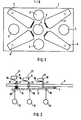
- Existing training wall 1 contains hit flaps 2, 5, 6 and 7.
- circular openings 3 can also be provided in the training wall 1. Such circular openings, which are adapted to the diameter of the ball, are located in the center of the training wall 1 and on both sides next to as well as above and below the center. If openings 3 are provided, a ball is inserted into the opening. 3 arrived, not used for the calculation of an evaluation number.
- the hit flaps 2, 5, 6 and 7 are trapezoidal and taper in the direction of the edges of the training wall 1.
- the hit flaps 2, 5, 6 and 7 are each articulated on the training wall 1 on their narrow sides facing the center.
- the four hit flaps 2, 5, 6 and 7 run radially in the direction of the four corners of the training wall 1.
- the hit flaps 2, 5, 6 and 7 are located at selected locations on the training wall 1. These selected locations, which can be referred to as target locations, are assigned position sensors, which are formed by switching elements, of which three switching elements 8, 9, 10 are shown in Fig. 2.
- the three switching elements 8, 9, 10 are switched on by the hit flap 2 by means of pin-shaped actuating elements 11, 12, 13 which protrude through holes in the training wall 1, which are not identified in any more detail.
- the ends of the pin-shaped actuating elements 11, 12, 13 rest on the one hand on the hit flap 2 and on the other hand on resilient flags 16 which belong to the switching elements 8, 9, 10 designed as limit switches.
- the switching elements 8, 9, 10 are at different levels with respect to the training wall 1, while the actuating elements 11, 12, 13 are of approximately the same length.
- the hit flap 2 is connected to a spring 14 which is supported on the hit flap 2 and on the training wall 1.
- the hit flap 2 is held by the spring 14 at a set distance from the training wall 1.
- the spring 14 is a compression spring.
- the pretension of the spring 14 can be adjusted by means of an adjusting nut 15 which can be screwed into a threaded bore (not shown).
- the adjusting nut 15 contains a central bore in which the actuating element 11 is guided.
- the hit flap 2 is pivotable about a hinge 4 which is attached to the training wall 1.
- the switching elements 8, 9, 10 of the top right hit flap 2 are assigned as position sensors. This hit flap 2 corresponds to a certain rating number. With the switching elements 8, 9, 10, the impact force of the ball is determined by which the spring 14 is compressed. When the ball hits the hit flap 2, it is pivoted about the hinge 4 and thereby compresses the spring 14.
- the switching elements 8, 9, 10 are assigned different evaluation numbers, which correspond to the different forces that are necessary to reduce the spring extension so much that the switching elements 8, 9, 10 each respond.
- the switching elements 8, 9, 10 are arranged in their distances from the training wall 1 or the hit flap 2 so that the switching element 10 switches with a small stroke, the switching element 9 only when the stroke is greater and the switching element 8 only switches when the spring 14 is almost compressed.
- the switching element 10, which switches first, is preferably assigned the smallest rating number and the switching element 8, which requires the largest stroke for switching, is assigned the highest rating number. You can display the rating number of the switching element 10 with the highest value, or add the rating numbers of the switching elements 8, 9 rated lower. If a ball 17 hits a certain impact energy in position 18, the spring 14 of the hit flap 2 is compressed only slightly. If the same ball 17 hits with the same energy in position 19, the spring 14 is compressed further than in the event of an impact in position 18.
- the spring 14 is compressed even further when the ball 17 hits a position 20 because the hit flap 2 works on the principle of a lever arm.
- the pulse is assigned to an appropriate evaluation number via an output 21 and sent to an evaluation circuit.
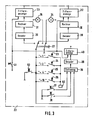
- FIG. 3 In the evaluation circuit arrangement 22 shown in FIG. 3, four switching elements 23, 24, 25, 26 which can be actuated by the hit flaps 2, 5, 6 and 7 are shown, to which the evaluation numbers one, two, four and ten are to be assigned. These evaluation numbers are shown in FIG. 3 on the lines leading to the switching elements 23 to 26 in quotation marks.
- the switching elements 23, 24, 25, 26 are each connected to an operating voltage at a connection.
- the other connections are connected to a changeover switch 27 which has two contact sets. One set of contacts, which is fed by the switching elements 23 to 26, is connected with an output to a second decoder 29.
- the decoders 28, 29 are each computer 30, 31 downstream of the outputs of which feed jewei 'ls number advertisements 32' 33rd
- the outputs of the second set of contacts of the changeover switch 27 are connected to a first display element 34 and to a second display element 35.
- the display elements 34 and 35 are each connected to the operating voltage when the components 29, 31, 33 or 28, 30, 32 are connected to the switching elements 23 to 26.
- the display elements 34, 35 thus serve as an indication of the operational readiness of the circuit part assigned to a player.
- a time measuring device 36 can be switched on by means of a switch 37.
- the time measuring device 36 can be a counter that counts clock pulses that are generated at a constant frequency by a clock generator.
- the time measuring device 36 can be set to a desired time elapse.
- a presettable counter can be used which emits a signal when the preset value is reached.
- the start of the time measurement can be selected by actuating a further switch 38.
- the timekeeping Direction 36 for example a binary counter, is followed by a decoder 39 which feeds a further numerical display 40. With the numerical display 40, the elapsed time after the actuation of the switch 38 is displayed.
- the digit displays 32, 33 and 40 can be seven-segment displays.
- the time measuring device 36 is stopped not only after the preset time has elapsed, but also after one or more switching elements 23 to 26 have been actuated. For this purpose, the time measuring device 36 is also included. the switching elements 23 to 26 connected. When a start button, not shown, is pressed, all the numerical displays 32, 33 and 40 are also set to zero.
- FIG 4 shows the entire display device 42, which contains the numerical displays 32, 33 and 40 and the display elements 34, 35, from the front.
- the rating number or a resulting rating number for a first player appears on the numerical display 32.
- the evaluation number results from the switching element 23 to 26 actuated by the ball. If there are several ball shots, the computer 30 determines the sum of the respective evaluation numbers, which appears on the numerical display 32 as the resulting evaluation number.
- the components 29, 31, 33 are ready for operation.
- the changeover to components 29, 31, 33 is carried out when a second player starts training, the resulting rating number for the first player for the purpose of comparison but should still be preserved.
- the changeover switch 27 can also be arranged after a single decoder, which is fed directly by the switching elements 23 to 26.
- the clock sequence of the clock pulses for the time measuring device 36 can be arbitrary, for example a time clock of approximately 10 seconds can be selected.
- the time from the actuation of the switch 38 to the actuation of a switching element 23 to 26 appears as a decimal number on the digital display 40, which is arranged below the digital displays 32, 33.
- the display elements 34, 35 show which of the assemblies 29, 31, 33 and 28, 30, 32 is currently connected to the switching elements 23 to 26.
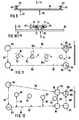
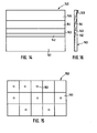
- the training wall 1 can be designed as a flat surface. It is also possible to construct a training wall 43 from two flat sections 44 which are inclined at an angle to one another and which are perpendicular to the floor. Such a training wall 43 is shown in FIG. 6. The ball 17 can strike the sections 44 and is deflected towards the center. It is advantageous here that the ball deflected towards the center is available again for a new training attempt in a shorter time.
- a training wall 45 can also consist of a central section 46 and two side sections 47 arranged at an angle to it. All sections 46, 47 are perpendicular to the floor. The side sections 47 direct the ball 17, if it hits it, towards the middle section 46.
- the angled design of the training walls 43 and 45 also results in increased stability. The effort for fastening the training walls 43, 45 is thereby somewhat less.
- additional deflecting bodies in the form of bevels, lenses and the like can be used. be arranged.
- the evaluation numbers of the two lower hit flaps 5, 6 are preferably lower than the evaluation numbers of the two upper hit flaps 2, 7, because the lower flaps are easier to play.
- the target locations for the ball 17 can be individual circular surfaces 48, 49, 50, 51, 52, 53, with each target surface being assigned a switching element with a corresponding evaluation number.
- the target areas can expediently consist of a covering of textile fabric or other elastic materials. When the ball 17 strikes, the covering bulges through, with corresponding switching elements being actuated. Here it can be assumed that the largest stroke is in the middle.
- the number, positioning, size and shape of the hit flaps can be adapted to the requirements in any way.
- the switching element positions of the switching elements 8, 9, 10 according to FIG. 2 are shown in connection with separate switching pins for the sake of clarity.
- all switching elements of a hit clap 2, 5, 6, 7 are actuated with a switching pin 54 which has adjustable actuating cams 55, 56.
- the actuating cams 55, 56 are set so that they - when the switching pin 54 moves in the direction designated 57.
- Flags 58, 59 are actuated by switching elements 60, 61 one after the other.
- One or any number of switching elements can be assigned to a hit target location. A switching element is then assigned to a hit target point if the hit should only display a desired value. If the strength of the shot is also to be taken into account, several switching elements are assigned to a hit target point, in order to reduce the amount of impact depending on the impact switch on the corresponding switching elements. Since the switch arrangement described calculates in steps, a type of circuit can preferably be selected which shows the hits on the numerical displays 32, 33.
- At least one switching element e.g. a microswitch, assigned, which is actuated upon impact of the ball as a result of the corresponding setting. If there is only one switching element per target location, the impact strength of the ball 17 can be determined in another way. The duration of the actuation of the switching element is measured in each case. The duration of the actuation is proportional to the impact force of the ball 17. Larger impact forces lead to a stronger compression of the spring 14 than smaller impact forces. It takes a longer time for the spring 14 to return to its original position with a larger impact force than with smaller impact forces, which corresponds to a longer actuation time.
- a switching element e.g. a microswitch
- the evaluation circuit 22 contains a pulse generator 62 which generates clock pulses of constant frequency.
- the pulse generator 62 is connected to the switching elements 23 to 26.
- Another switch 63 is arranged in the circuit between the pulse generator 62, the switching elements 23 to 26 and the operating potential. When the switch 63 is open, the energy supply to the switching elements 23 to 26 is interrupted.
- Each switching element 23 to 26 is assigned an evaluation number which is based on the degree of difficulty which is decisive for a hit.
- the number of clock pulses is further processed by the computer 30 or 31 as an evaluation number for the impact force of the ball 17.
- the switching element 23 which has the value "1" due to its position, the number 4 or the number 24 already forms the final evaluation number.
- the switching element e.g. the evaluation number "2”
- the computer 30 or 31 multiplies this number by 4 or 24.
- the product is displayed as the resulting evaluation number on the numerical display 32 or 33.
- the evaluation numbers for the position and the impact force are therefore multiplicatively linked to one another in the arrangement according to FIG. 3.
- An inductively operating switch in which no wear occurs, can expediently be used as the switching element.
- the pulse frequency of the generator 62 is chosen according to the respective conditions.
- the time measuring device 36 After the period of time set in the time measuring device 36 has elapsed, the time measuring device 36 opens the switch 63 and thus prevents the switch from being started again without actuating the switch. It is possible to try several games in succession and the result as to display the resulting evaluation number on the display device 42.
- the time determined by the time measuring device 36 can also be included in the resulting evaluation number. This can e.g. additive, subtractive or multiplicative.
- the resulting rating number is then a measure of the level of difficulty, the impact and the time required for the respective game.
- a training wall 64 can be connected at the four corners with springs 65, which are each located between the training wall 64 and a stationary pressure plate 66.
- the training wall 64 contains no hit flaps. Due to the resilient fastening, the training wall 64 carries out 17 displacement movements and / or pivoting movements depending on the point of impact of the ball. The movements are measured using switching elements, not shown.
- Each spring 65 is assigned two switching elements, not shown, which are permeable for the clock pulses of a clock generator according to the impact strength.
- the training wall 69 shown in FIG. 10 is arranged to be pivotable about a vertical axis 70.
- the axis 70 is connected to the training wall 69 and therefore executes the pivoting movements with it.
- Two springs 72, 73 are supported on a support plate 71 on both sides of the axis 70.
- the springs 72, 73 are located between the support plate 71 and a stationary i fixed plate 74. Also, between the support plate 71 and the stationary plate 74 are arranged two switches 75 '76th When the ball 17 hits the center 77, the springs 72, 73 are not compressed. Therefore, the switches 75, 76 do not respond.
- the training wall 29 is pivoted in the direction 79.
- the distance 80 between the support plate 71 and the plate 74 decreases depending on the distance of the impact point from the center 77 and the impact force of the ball 17.
- a dribble path 81 which has a plurality of vertical posts 82 which are arranged in a row at a distance from one another in the middle of the dribble path 81.
- the dribble path 81 there are four vertical columns 83, 84, 85, 86. Beam columns which, for example, emit infrared rays or ultrasound waves are arranged in the columns 83 to 86. Infrared light barriers are preferably used.
- an infrared transmitter for example, is attached, which is aligned with an infrared receiver in the column 84. The transmitter and receiver form an infrared path 87 on the front narrow side of the dribble path 81. This narrow side forms the inlet side of the dribble path 81.
- a lateral infrared path 88 is formed by this transmitter un.
- An infrared transmitter, not shown, is arranged in the column 84 and is aligned with an infrared receiver in the column 86. This transmitter forms the second lateral infrared path 89 with the receiver.
- Another infrared transmitter, not shown, is arranged in the column 85 and is aligned with an infrared receiver, not shown, in the column 86.
- the last-mentioned transmitters and receivers form an infrared path 90 at the exit of the dribble path 81.
- the dribble path 81 is accordingly delimited by the infrared paths 87, 88, 89 and 90.
- the dribble path 81 thus corresponds to a dribble path with inserted rods, through which a soccer player must pass the ball during training.
- the column 85 there is also a time measuring device 91 and a deflection counter 92.
- a further deflection counter 93 is arranged in the column 86.
- keys 94, 95 are provided, with which the contents of the counters 92, 93 and the timepiece 91 can be deleted.
- the respective player When entering the dribble path 81, the respective player interrupts the infrared path 87.
- the signal generated by the infrared receiver in the column 84 in response to the interruption causes the connection of the infrared paths 88, 89 and 90.
- the time measuring device 91 and the counters 92, 93 in Ready for operation.
- the player is supposed to run the ball around the posts 82 in the slalom, indicated by the direction 96. If the player's ball or leg is deflected to the side so far that infrared paths 88 or 89 are interrupted, a rating number is added to the Counters 92 and 93 generated and displayed.
- the rating number can be chosen arbitrarily.
- the infrared path 90 After passing through the dribble path 81, the infrared path 90 is interrupted. The infrared receiver generates a signal via which the infrared links 87, 88, 89 and the time measuring device 91 are stopped. After passing through dribble path 81, the ball must be shot towards training wall 1. Thereafter, the displays of the time measuring device 91 and the counters 92, 93 can be deleted using the keys 94, 95.
- the routes 88, 89 can be lengthened or shortened as desired, i.e. the width of the dribble path is changed.
- the degree of difficulty can be increased if further obstacles 82a are placed in addition to the obstacles 82.
- a dribble path 97 is conical, as shown in FIG. 12.
- the dribble path 97 tapers towards its end.
- the dribble path 97 also contains columns 83, 84, 85, 86, which, like the corresponding columns of the dribble path 81, are equipped with beam barriers.
- the infrared path 87 runs between the columns 83, 84.
- the infrared path 89 runs between the columns 84, 86.
- Posts 82 are arranged on the dribble path 97 as obstacles, the distances 99 of which from the infrared path 89 decrease in the direction of the end of the dribble path 97.
- An infrared path 98 runs between the columns 83 and 85, which is longer than the infrared path 88 due to the conical design of the dribble path 97.
- the counters 92, 93 and the time measuring device 91 can be arranged in the columns 85, 86 as well as in the case of the dribble path 81. However, these parts are not shown in FIG. 12. As with the dribble path 81, the infrared path 90 runs between the columns 85, 86.
- the two columns 85, 86 are followed by two further columns 100, 101.
- An infrared transmitter and an infrared receiver are each arranged in the columns 100, 101, which generate an infrared path 102.
- a lamp 103 is arranged in the column 100. The lamp 103 is controlled by a time circuit which can be set to a desired runtime.
- the dribble path 81, 97 can be used alone or in combination with a training wall 1, 43, 45, 64, 69.
- the player In combination with the training wall, the player has to shoot the training wall 1, 43, 45, 64, or 89 after passing through the infrared path 90, where the dribble path 81, 97 is displayed separately or in conjunction with the control circuit.
- a target point on the training wall is switched on by interrupting the infrared path 90 via a connecting line 124 and a probability calculator to be explained below.
- the infrared path 90 is interrupted, the time cycle which expires after any time to be set is switched on. The ball must be shot quickly after the infrared path 90 has been interrupted, because a rating within the running time of the time cycle is only given if the infrared path 102 is interrupted within this time.
- the lamp 103 lights up if the infrared link 102 is interrupted before the time circuit is switched off.
- a display element 104 lights up and there is no scoring on the electronic ball game wall.
- the display element 104 is arranged in the column 100.
- Dribble path 81, 97 can be used as sport training without obstacles in order to train according to basic speed.
- the obstacles can also be constructed in combination as slalom obstacles or cross obstacles.
- Difficult exercises can be carried out with the dribble path 97 because the lateral distances between the obstacles 82 and the dribble path boundaries become smaller with increasing length.
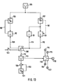
- a control circuit for the dribble path 97 is shown in FIG. 13.
- the control circuit contains a signal generator 105 which emits a signal when the infrared path 87 is interrupted.
- the signal transmitter 105 is connected to the transmit / Spangrup- p s 106, 107 of the two infrared lines 89 and 98 respectively.
- the transmitter / receiver modules 106, 107 are switched on by the output signal of the signal generator 105.
- the deflection counters 92, 93 are connected downstream of the receivers of the transmission / reception modules 106, 107.
- the time measuring device 91 is also connected to the receiver of the transmitting / receiving module 107 and, like the deflection counters 92, 93, is switched ready for operation when the signal from the signal generator 105 occurs.
- the infrared paths 89, 98 are also shown symbolically to indicate that the deflection counters 92, 93 determine the number of interruptions in the infrared paths 98, 99.
- the transmitting / receiving module 108 which generates the infrared path 90 is connected to control inputs of the deflection counters 92, 93 and the time measuring device 91 via lines 109, 110, 111. With the transmit / receive module 108 is via a control line 112 is connected to a random number generator 113 which, according to its random number in the training wall 1, 43, 45, 64, 69, controls one of a number of indicator lights 114, 115, 116, 117 which are in the training wall 1, 43, 45, 64 or 69 Target locations are assigned.
- the target locations include position and impact force sensors, of which a sensor 118 is shown in FIG. 13.
- the indicator lights 114 to 117 and the sensors 118 are selected via an addressing circuit 119.
- the random number generator 113 is followed by a time circuit 120, which is triggered via the transmit / receive module 108.
- time circuit 120 an expiry time is set within which the ball must have been shot on training wall 1, 43, 45, 64 or 69.
- the time circuit 120 is reset by the transmitting / receiving module of the infrared link 102 via a line 122 or after the preset time has elapsed.
- the time runs until the infrared path 90 is interrupted.
- the running time of the time measuring device 91 is switched off via the line 111, the status being displayed.
- the deflection counters 92, 93 are switched off via the lines 109, 110, so that - if the lateral stretches have been interrupted - there is no enumeration.
- the transmitting / receiving module 108 switches on the random number generator 113, which switches on one of the display elements 114-117 and supplies the associated sensor.
- the time cycle 120 is started, in which a time expires in which the ball must be shot onto the training wall in order to obtain a rating.
- the training wall is no longer used.
- the training wall is also no longer scored because the line of fire has been crossed.
- the player trains dribbling with it, after dribbling a goal shot with quick reaction; because the lamp, which is switched on by the random number generator 113, symbolizes: here the goal is not covered by the goalkeeper.
- the control circuit is set to zero via a key 123 and is then ready to start again.
- the values can be printed out automatically for the receipt.
- a particularly favorable way of assigning assessment numbers to the position encoders is to supply them with clock pulses at different frequencies.
- the lamella surfaces 142 to 145 can be flat or, as in FIG. 16, be arranged differently at an angle.
- the rebounding ball is pressed upwards or downwards with the obliquely arranged lamella surfaces 142 to 145.
- An electronic evaluation is switched in such a way that only one lamella surface 141 to 145 delivers a rating, even if in the limit case two lamella surfaces 141 to 145 are hit by a ball 17.
- a reaction wall 150 is shown in FIG. 1.5, as can additionally be used in handball, football or for physical condition training by touching the body.
- the area of the reaction wall 150 is divided into value fields 151, which can be the same or different in size.
- the value fields or sensors 151 z.
- a football wall 150 can be switched on via a random generator, which only switches on one or more value fields or sensors 151, which perform an evaluation when played.
- the activated value fields or sensors 151 are optically indicated by lamps 152.
- each hit can be shown on a separate display.
- 150 play points can be set on a training wall, which change via a random generator on hit or after an arbitrary time. Depending on the requirements, only hits or hits with impact strength can be rated here.
- the limitation of the training duration can be determined by the elapsing time or by any number of surcharges.
- the wall, cabin, floor or wall with floor 170, 180 can be designed so that the optically or acoustically (for condition and reaction) indicated sensors 171 and 182 are designed so that gymnastics or conditioning exercises they have to be touched with a body part, e.g. B. with hands, feet, by bending down, jumping, pulling, pushing or the like. Each exercise is assigned individually or in combination a score.
- the training wall can be mounted in a height or laterally changeable.
- the training floor 180 can also be designed such that light paths Fig. 183, 184, 185 are used, which are also controlled by the random generator and are considered an obstacle in the training process that must be skipped or require other exercises.
- spoken instructions can also be given synchronously to the random generator, which are queried for the corresponding combination from the electronic memory and transmitted via a microphone.
- the performance that is performed is visually displayed as a value, it can also be printed out.
Landscapes
- Health & Medical Sciences (AREA)
- General Health & Medical Sciences (AREA)
- Physical Education & Sports Medicine (AREA)
- Pinball Game Machines (AREA)
- Rehabilitation Tools (AREA)
Applications Claiming Priority (2)
| Application Number | Priority Date | Filing Date | Title |
|---|---|---|---|
| DE3322901 | 1983-06-25 | ||
| DE19833322901 DE3322901A1 (de) | 1983-06-25 | 1983-06-25 | Trainingswand mit elektronischer auswertung der anspielposition und der aufprallstaerke |
Publications (2)
| Publication Number | Publication Date |
|---|---|
| EP0130238A2 true EP0130238A2 (fr) | 1985-01-09 |
| EP0130238A3 EP0130238A3 (en) | 1986-05-28 |
Family
ID=6202366
Family Applications (1)
| Application Number | Title | Priority Date | Filing Date |
|---|---|---|---|
| EP83111052A Withdrawn EP0130238A3 (en) | 1983-06-25 | 1983-11-05 | Training device, particularly for ball games |
Country Status (2)
| Country | Link |
|---|---|
| EP (1) | EP0130238A3 (fr) |
| DE (1) | DE3322901A1 (fr) |
Cited By (4)
| Publication number | Priority date | Publication date | Assignee | Title |
|---|---|---|---|---|
| GB2270004A (en) * | 1992-08-27 | 1994-03-02 | David William Nelson | Physical exercise apparatus |
| EP0904807A3 (fr) * | 1997-09-24 | 1999-07-21 | Cetoni Umweltechnologie-entwicklungsgesellschaft mbH | Jeu de balle |
| RU189754U1 (ru) * | 2018-05-30 | 2019-06-03 | Ярослав Валерьевич Голуб | Устройство оценки и тренировки реакции |
| RU194533U1 (ru) * | 2019-08-08 | 2019-12-13 | Валерий Михайлович Зыков | Тестер-тренажер реакции |
Families Citing this family (4)
| Publication number | Priority date | Publication date | Assignee | Title |
|---|---|---|---|---|
| DE3522919A1 (de) * | 1985-06-27 | 1987-01-08 | Adalbert Prof Dr Nagy | Vorrichtung zur perfektionierung von fussballern |
| JPH0194876A (ja) * | 1987-10-05 | 1989-04-13 | Panpacific Kk | 球技用具 |
| NO20002338L (no) * | 2000-05-03 | 2001-11-05 | Stigra H Eriksen Eftf As | Treningsanordning |
| DE20305646U1 (de) * | 2003-04-08 | 2003-11-20 | Cappelmann, Kai, 27580 Bremerhaven | Trainingswand für Fußballspieler |
Family Cites Families (8)
| Publication number | Priority date | Publication date | Assignee | Title |
|---|---|---|---|---|
| US2789822A (en) * | 1955-02-07 | 1957-04-23 | Faizi Salih | Target with electrical indicator |
| GB1234909A (en) * | 1969-10-25 | 1971-06-09 | Arthur William Ready | Apparatus for use in tests of skill |
| US4116437A (en) * | 1973-02-08 | 1978-09-26 | Johnson Neil E | Tennis training and rating apparatus |
| GB1461691A (en) * | 1974-01-08 | 1977-01-19 | Barboza J M | Sports 'raining equipment |
| DE2758290A1 (de) * | 1977-01-06 | 1978-07-13 | Remy Torres | Sportgeraet |
| US4199141A (en) * | 1978-03-27 | 1980-04-22 | Garcia Abril I | Baseball pitching scoring apparatus |
| US4309032A (en) * | 1979-05-24 | 1982-01-05 | Facius Walter P | Tennis training device |
| EP0083316A1 (fr) * | 1981-12-24 | 1983-07-06 | Manlio Marchesini | Appareil pour jouer au tennis contre un mur |
-
1983
- 1983-06-25 DE DE19833322901 patent/DE3322901A1/de not_active Withdrawn
- 1983-11-05 EP EP83111052A patent/EP0130238A3/de not_active Withdrawn
Cited By (5)
| Publication number | Priority date | Publication date | Assignee | Title |
|---|---|---|---|---|
| GB2270004A (en) * | 1992-08-27 | 1994-03-02 | David William Nelson | Physical exercise apparatus |
| GB2270004B (en) * | 1992-08-27 | 1995-09-20 | David William Nelson | Physical exercise apparatus |
| EP0904807A3 (fr) * | 1997-09-24 | 1999-07-21 | Cetoni Umweltechnologie-entwicklungsgesellschaft mbH | Jeu de balle |
| RU189754U1 (ru) * | 2018-05-30 | 2019-06-03 | Ярослав Валерьевич Голуб | Устройство оценки и тренировки реакции |
| RU194533U1 (ru) * | 2019-08-08 | 2019-12-13 | Валерий Михайлович Зыков | Тестер-тренажер реакции |
Also Published As
| Publication number | Publication date |
|---|---|
| EP0130238A3 (en) | 1986-05-28 |
| DE3322901A1 (de) | 1985-01-03 |
Similar Documents
| Publication | Publication Date | Title |
|---|---|---|
| DE2831383C2 (fr) | ||
| EP1759737B1 (fr) | Dispositif d'entraînement | |
| EP0074516B1 (fr) | Billard | |
| EP3352865B1 (fr) | Appareil de jeu pour sport de balle utilisant une paroi de rebond | |
| DE29617403U1 (de) | Trainings- oder Spielgerät für insbesondere Ballspiele | |
| DE4306682A1 (fr) | ||
| EP0130238A2 (fr) | Dispositif d'entraînement en particulier pour jeux de balle | |
| EP0210539B1 (fr) | Appareil pour jouer à la balle avec une parois de rebond fixée sur un support portatif | |
| DE2410174A1 (de) | Verfahren und einrichtung zur bestimmung von richtung und groesse des dralles von spiel-, insbesondere von golfbaellen | |
| DE69002418T2 (de) | Schiessspielmaschine. | |
| DE3010084A1 (de) | Zielvorrichtung fuer ein flipper-spielgeraet | |
| DE102007017732A1 (de) | Trainingsgerät mit einem antreibbaren Laufband | |
| AT397206B (de) | Verfahren und trainingsvorrichtung zur bestimmung der optimalen wurf-, schuss- bzw. abspieltrainingsgeschwindigkeit bei wurfsportarten bzw. ballspielen | |
| DE3304346A1 (de) | Spielgeraet, insbesondere flipper-spielgeraet | |
| LU500461B1 (de) | Trainingsvorrichtung | |
| WO2004009188A1 (fr) | Appareil pour jeu competitif impliquant l'utilisation d'un ballon de basket et d'un panier de basket | |
| EP0927365B1 (fr) | Dispositif pour mesurer la vitesse d'objets varies | |
| DE8100135U1 (de) | Spielgeraet, insbesondere zur simulierung eines ballspiels nach art von tennis | |
| DE29909729U1 (de) | Vorrichtung eines Fußballspielfeldes mit Toren | |
| EP0098519A2 (fr) | Dispositif de contrôle du mouvement et de la tenue d'une raquette | |
| DE19726565C2 (de) | Vorrichtung zur Trefferauswertung bei Spielen | |
| DE112004001264B4 (de) | Abschlagsmatte für einen Golfball | |
| DE2609458A1 (de) | Tischfussball-geraet zum reaktionstraining unter verwendung von permanent-magneten | |
| AT413652B (de) | Spielgerät und verfahren zur darstellung des laufes der kugel | |
| DE2057485A1 (de) | Trainingswand fuer Ballspieler |
Legal Events
| Date | Code | Title | Description |
|---|---|---|---|
| PUAI | Public reference made under article 153(3) epc to a published international application that has entered the european phase |
Free format text: ORIGINAL CODE: 0009012 |
|
| AK | Designated contracting states |
Designated state(s): AT BE CH DE FR GB IT LI LU NL SE |
|
| PUAL | Search report despatched |
Free format text: ORIGINAL CODE: 0009013 |
|
| AK | Designated contracting states |
Kind code of ref document: A3 Designated state(s): AT BE CH DE FR GB IT LI LU NL SE |
|
| STAA | Information on the status of an ep patent application or granted ep patent |
Free format text: STATUS: THE APPLICATION IS DEEMED TO BE WITHDRAWN |
|
| 18D | Application deemed to be withdrawn |
Effective date: 19860603 |