EP0098709A1 - Flüssigkeitsabgabesystem - Google Patents
Flüssigkeitsabgabesystem Download PDFInfo
- Publication number
- EP0098709A1 EP0098709A1 EP83303554A EP83303554A EP0098709A1 EP 0098709 A1 EP0098709 A1 EP 0098709A1 EP 83303554 A EP83303554 A EP 83303554A EP 83303554 A EP83303554 A EP 83303554A EP 0098709 A1 EP0098709 A1 EP 0098709A1
- Authority
- EP
- European Patent Office
- Prior art keywords
- station
- count
- counter
- meter
- line
- Prior art date
- Legal status (The legal status is an assumption and is not a legal conclusion. Google has not performed a legal analysis and makes no representation as to the accuracy of the status listed.)
- Granted
Links
- 239000007788 liquid Substances 0.000 title claims abstract description 46
- 230000000694 effects Effects 0.000 claims description 9
- 230000002452 interceptive effect Effects 0.000 claims 1
- 238000011144 upstream manufacturing Methods 0.000 claims 1
- 239000012530 fluid Substances 0.000 description 5
- 239000007787 solid Substances 0.000 description 3
- 230000000295 complement effect Effects 0.000 description 2
- 238000010586 diagram Methods 0.000 description 2
- 238000007493 shaping process Methods 0.000 description 2
- PCTMTFRHKVHKIS-BMFZQQSSSA-N (1s,3r,4e,6e,8e,10e,12e,14e,16e,18s,19r,20r,21s,25r,27r,30r,31r,33s,35r,37s,38r)-3-[(2r,3s,4s,5s,6r)-4-amino-3,5-dihydroxy-6-methyloxan-2-yl]oxy-19,25,27,30,31,33,35,37-octahydroxy-18,20,21-trimethyl-23-oxo-22,39-dioxabicyclo[33.3.1]nonatriaconta-4,6,8,10 Chemical compound C1C=C2C[C@@H](OS(O)(=O)=O)CC[C@]2(C)[C@@H]2[C@@H]1[C@@H]1CC[C@H]([C@H](C)CCCC(C)C)[C@@]1(C)CC2.O[C@H]1[C@@H](N)[C@H](O)[C@@H](C)O[C@H]1O[C@H]1/C=C/C=C/C=C/C=C/C=C/C=C/C=C/[C@H](C)[C@@H](O)[C@@H](C)[C@H](C)OC(=O)C[C@H](O)C[C@H](O)CC[C@@H](O)[C@H](O)C[C@H](O)C[C@](O)(C[C@H](O)[C@H]2C(O)=O)O[C@H]2C1 PCTMTFRHKVHKIS-BMFZQQSSSA-N 0.000 description 1
- 230000003321 amplification Effects 0.000 description 1
- 238000010276 construction Methods 0.000 description 1
- 230000009977 dual effect Effects 0.000 description 1
- 230000006870 function Effects 0.000 description 1
- 230000002401 inhibitory effect Effects 0.000 description 1
- 238000007689 inspection Methods 0.000 description 1
- 239000000314 lubricant Substances 0.000 description 1
- 238000000034 method Methods 0.000 description 1
- 238000003199 nucleic acid amplification method Methods 0.000 description 1
- 230000002085 persistent effect Effects 0.000 description 1
- 238000010187 selection method Methods 0.000 description 1
Images


Classifications
-
- B—PERFORMING OPERATIONS; TRANSPORTING
- B67—OPENING, CLOSING OR CLEANING BOTTLES, JARS OR SIMILAR CONTAINERS; LIQUID HANDLING
- B67D—DISPENSING, DELIVERING OR TRANSFERRING LIQUIDS, NOT OTHERWISE PROVIDED FOR
- B67D7/00—Apparatus or devices for transferring liquids from bulk storage containers or reservoirs into vehicles or into portable containers, e.g. for retail sale purposes
- B67D7/04—Apparatus or devices for transferring liquids from bulk storage containers or reservoirs into vehicles or into portable containers, e.g. for retail sale purposes for transferring fuels, lubricants or mixed fuels and lubricants
-
- B—PERFORMING OPERATIONS; TRANSPORTING
- B67—OPENING, CLOSING OR CLEANING BOTTLES, JARS OR SIMILAR CONTAINERS; LIQUID HANDLING
- B67D—DISPENSING, DELIVERING OR TRANSFERRING LIQUIDS, NOT OTHERWISE PROVIDED FOR
- B67D7/00—Apparatus or devices for transferring liquids from bulk storage containers or reservoirs into vehicles or into portable containers, e.g. for retail sale purposes
- B67D7/06—Details or accessories
- B67D7/08—Arrangements of devices for controlling, indicating, metering or registering quantity or price of liquid transferred
-
- B—PERFORMING OPERATIONS; TRANSPORTING
- B67—OPENING, CLOSING OR CLEANING BOTTLES, JARS OR SIMILAR CONTAINERS; LIQUID HANDLING
- B67D—DISPENSING, DELIVERING OR TRANSFERRING LIQUIDS, NOT OTHERWISE PROVIDED FOR
- B67D7/00—Apparatus or devices for transferring liquids from bulk storage containers or reservoirs into vehicles or into portable containers, e.g. for retail sale purposes
- B67D7/06—Details or accessories
- B67D7/08—Arrangements of devices for controlling, indicating, metering or registering quantity or price of liquid transferred
- B67D7/22—Arrangements of indicators or registers
- B67D7/221—Arrangements of indicators or registers using electrical or electro-mechanical means
- B67D7/222—Arrangements of indicators or registers using electrical or electro-mechanical means involving digital counting
Definitions
- This invention relates to a Liquid dispensing system for dispensing measured quantities of a Liquid at a number of discrete Locations from a single source. More particularly the invention relates to a system for use in garage workshops and similar areas to dispense metered quantities of oil or the like.
- the meters in present use in retail outlets must have in the United Kingdom Board of Trade approval to protect customers and to ensure accuracy. Satisfactory meters are relatively Large and heavy and come essentially in two kinds. Firstly, there are the wall-mounted meters which are the Larger of the two kinds. These must be mounted on a secure structure and supplied with oil Lines from the pump and to the delivery hose. It'has a Large meter dial which can be set to zero and which can be seen from some distance off.
- a Liquid dispensing system comprising a plurality of dispensing stations, a pump means and a meter to measure the quantity of liquid pumped by the pump means to the dispensing stations, characterised in that the system includes a control station and each dispensing station comprises a dispensing point for the liquid and a display and the control station comprises electronic means to select and enable any one dispensing station whereby Liquid is dispensible at that station, to disable the other dispensing station or stations whereby Liquid is not dispensible at said other station or stations, to monitor the meter and to effect a reading on the display at said one dispensing station, said reading corresponding to the volume of Liquid passing through the meter and being dispensed at said one dispensing stati-on.
- said electronic control means includes means to disable and cancel any existing selection of a station when another station is selected.
- ALternativeLy said electronic control means includes means enabling a number of stations to be selected but one only to be enabled when a previously enabled station is unselected.
- the main advantage of the system according to the present invention is that only a single meter is employed for dispensing to a number of separate dispensing stations such that the risk of Leaks is reduced and more importantly the capital cost of the system is considerably reduced.
- hoses having removed the bulky meters from the scene of dispensing. For instance helically coiled hoses of the type familiarly used for air Lines in heavy vehicles may be used. These hoses are neater, Less bulky and do not require coiling and storage apparatus. Also, because they can twist quite easily there is no requirement for swivel joints at the dispensing nozzle which has hitherto particularly been the case where hose-end meters were employed. Removing swivel joints of'course reduces still further the risk of leaks.
- the display is an entirely separate entity from the Liquid supply Line and so, unlike wall-mounted meters, the display may be mounted at any convenient point. For instance most dispensing of oil to cars in garage workshops takes place while the car is on a hydraulic lift, often of the two or four post variety. Thus a very convenient Location for mounting of the display is often on one of the Lift posts.
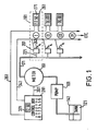
- An oil dispensing system is schematically illustrated in Fig.1 and comprises a supply 121 of oil in tank 141, a pump 101, a meter 161 and dispensing stations 181 disposed around a work area.
- Each dispensing station requires oil and needs to know how much is being delivered. Thus it is imperative that only one station 181 is allowed to withdraw oil at a time and that a reading indicating how much oil has been taken is available to that station.
- control means in a control box 281 monitors along Line 301 the state of the meter 161 which is arranged to establish pulses in Line 301 as precise known volumes of oil pass through it. That is to say each pulse represents a specified volume of fluid.
- the control box under manual supervision, also controls which station receives the oil. Any one of six stations may be selected (although the system can accommodate up to 15 stations as is explained beLow) and this has the effect of resetting the display 321 to zero and via Line 341 opening a solenoid valve 201 disposed in a branch 221 of supply Line 171 to the station selected. Other solenoid valves disposed in similar branches to other stations remain closed such that only the station selected can withdraw oiL. Withdrawal of oil is effected once a station has been selected by opening a tap (not shown) at the end of coiled hose 241.
- the control box also arranges, by means explained below, to display on a display 271 the reading showing on display 321. This reading is displayed only at the station selected,all zeros being relayed to the other stations.
- Box 261 containing display 271 can be mounted at-any convenient point entirely independently of the branch 221, valve 201 or hose 241. Thus it does not require robust construction because it can be disposed out of harms way. Moreover, the control box 281 does not require to be adjacent the meter 161 but can in fact be disposed wherever convenient. If security from pilfering is required it can be disposed in a workshop stores area where records of oil dispensed and at which station can be made.
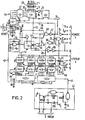
- FIG.2 A convenient Logic circuit for putting the invention into effect is illustrated in Fig.2.
- SeLection of a station causes a four bit binary coded decimal (BCD) code unique to that station to be applied at 2 along Lines ABCD.
- BCD codes are in numerical order with the first station being coded 0001, the second 0010 etc up to a maximum of 1111 for the fifteenth. This code is applied to a quad D-register 10 but is only Loaded thereto when it receives an enabling signal along Line 12 from decade counter divider 14.
- Decade counter divider 14 receives a continuous stream of pulses from clock pulse generator 16 once the dispensing system is energised and the counter 14 immediately begins counting. On the count of 2, an enabling signal is applied to Line 12 which, while Loading register 10 also presets BCD programmable up/down counter 18 with a preselected four bit BCD-code from switch 20. The counter 18 is set to count down.
- the four bit BCD code from switch 20 represents the total number of dispensing stations in operation which, in the present instance, is six or 0110 in binary.
- the enabling signal in Line 12aLso resets to zero a 7-stage binary counter 22 which is arranged to receive clock pulses along Line 24.
- the counter 22 is so arranged that every 32 pulses it receives along Line 24 one pulse is applied to Line 26 and thus, via NOT gate 28, to counter 18.
- PuLses applied to counter 18 count it down from the preselected value input by switch 20. The value remaining in the counter 18 at any time; is applied; via Lines 30; to comparator 32 which also receives via Lines 34 the BCD value stored in register 10 and representing the station selected.
- comparator 32 When the BCD value in counter 18 is the same as is stored in register 10 comparator 32 provides an enabling signal along Line 36.
- the four four-bit BCD counts subsisting in counters 42a and b -at any given time are applied to BCD-to-7-segment Latch decoder drivers 41a to 41d. If 0000 is applied to driver 41d then this driver is disabled by NOR gate 44 to prevent a Leading zero from being displayed. Furthermore, if the individual segments of the displays are to be checked flash ciruit 46 causes decimal 8's to be applied to the registers 40a to 40d.
- each register 40a to 40d has its eighth input connected to 1 indicating that the decimal point will appear before the numeral stored in register 40b. That is to say the total number stored is in the form: 12.34 .
- the enabling signal on Line 12 which occurs at the count of 2 in counter 14, as well as presetting counter 18, it also causes the counter 18 to provide an enabLing signal on Line 50 which is only subsequently removed when the count in counter 18 eventually reaches zero.
- the enabling signal on Line 52 allows pulses from the clock pulse generator 16 on Line 58 to pass through NAND gate 60 and NOT gate 62 to emanate on Lines 24 where they are counted in counter 22.
- the count in counter 18 is reduced by one.
- the comparator 32 establishes an enabling signal on Line 36. It does this for only 32 counts in counter 22 because beyond this the count in counter 18 is reduced still further and hence is no Longer the same as that stored in register 10.
- an enabling signal in Line 36 enables gates 64 and 66 respectively.
- the same information is progressively shifted via terminal 5d and line 70 into four 8-stage serial input/ parallel output shift registers 78a to 78d comprising the REMOTE display 271 of a first dispensing station I.
- the counter 14 applies an enabling signal to Line 82 which is transfered by gates 84,86 to terminals 4e and 5e.
- the signal in Line 82 enables all the 7-segment displays 90 to read what is in their respective registers 74,78,80 etc. and to display that information.
- this information will be that which a few pulses before had been stored in registers 40 while the rest will be supplied with all zeros.
- CLearLy the REMOTE display 271 which displays this information should be the display which is a part of the dispensing station which has been selected and this is effected by suitable choice of the BCD code applied to register 10 on selection of a station. The further that the information has to move away from its source in registers 40, then the sooner it must be allowed to enter the train; and the sooner it must enter the train then the Larger the BCD-code must be in register 10 so that the count in counter 18 is reduced to that value sooner.
- the second station is selected on the control box 281 which means the solenoid valve of this station is opened and oil can be withdrawn.
- the register 10 After the next count of two in counter 14 the register 10 will be Loaded with the number 0010 (two) and the counter 18 with the preselected code 0110 (six stations). During the first set of 32 pulses, zeros will be entered in the first display and at the end of those pulses the counter 18 will be reduced to 0101 (five).
- the count in counter 18 will have been reduced to 0001 (one) and zeros will again be entered in the first display while the information in the first display is shifted into the second display.
- the zeros in displays 2 to 5 are also shifted to displays 3 to 6.
- the count in counter 18 changes to 0000 (zero) and no more pulses will be allowed to shift the displays because counter 18 disables gate 60 when it is reduced to zero.
- the displays are instructed to show what they have stored in their respective registers.
- the second display has the information previously held in registers 40. When the second station is first selected this information would of course be zeros as well but once oil is dispensed and the count in counters 42 change then the information displayed will also change giving an indication of the volume dispensed.
- one complete revolution of the main spindle means that one Litre of fluid has passed through it.
- a disc having 100 slots arranged circumferentially around it is mounted on the spindle.
- a Light source and Light receptor are mounted on either side of the disc in such a way that Light from the source can pass through a slot to impinge on the receptor.
- the spokes separating the slots cut off the Light to the receptor and this estabLishs a pulse which after amplification and shaping is fed to terminal 3b in the control box 281.
- each puLse represents one hundredth of a Litre so if the display shows: 12.34, then this means that 12.34 Litres of oil have passed through the meter.
- selection of a station is effected, not at the control box 281 but at each dispensing station.
- more than one station may be selected at any one time although it must be ensured that only one station can be supplied with oil at any instant of time.
- selection is effected at a station it is not necessary to arrange a display at the control box. This embodiment therefore is used as a straight alternative to existing methods of oil delivery and where no extra security is required.
- the control box would be placed anywhere convenient, perhaps adjacent the meter.
- a Light on the display box 261 indicates that the selection is made. Any number of stations may be selected: Only one station at a time is actually enabled however and the fact that a station is enabled is signalled to the operator by means of the display becoming activated. The displays at the other stations remain blank even if they have been selected. If other stations have been selected the control box "stacks" or “queues” those selections by means explained below until the station which was enabled is actually unselected. Then the next station in the queue is selected.
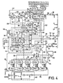
- a clock pulse generator 110 produces a continuous stream of pulses in Line 111 which are fed to two decade counter dividers 112,114 which, while they are counting, produce enabling signals on specific Lines after specified counts.
- counter 112 produces enabling signals on Lines 120,122, 124,126 and 128 on counts 0,2,4,6 and 8 respectively while counter 114 produces enabling signals on Lines 132,134,136 and 138 on counts 2,4,6 and 8 respectively.
- each display 271 comprises, in addition to the components present in the displays of the previous embodiments and illustrated in Fig.3, a D fLip-fLop 143 whose reset Line 144 is connected via two-way switch 146 to "zero". Moreover each display is connected to the next in-line or to the circuit of Fig 4 from outputs AO to FO to corresponding inputs AI to FI or inputs A to F respectively.
- the most remote display has its inputs AI to FI unconnected.
- the D input to its D-fLip-fLop is always at "one”.
- the D inputs and Q outputs are aLL at "one”.
- the state of Q and Q determines from which four registers 162a to e the count is taken.
- the meter sends pulses corresponding to known volumes of oiL to reshaping circuit 182 where the pulses are applied to the first counter 164a on Line 184.
- a count of zero also resets Latch 186 via Line 120 such that a "one" is applied to Line 188 (a zero subsists in Line 124 at this stage) and thence to 4-stage binary programmable up/down counter 190 and sets it to count UP.
- the "one” in Line 120 also resets counter 190 to 0000 via Line 192.
- Via Line 193, 7-stage binary counter 195 is reset to zero by the "one" in Line 120.
- D fLip-fLop 196 is reset to give a "one" on its Q output which, via Line 198, enables NAND gate 200.
- a pulse in Line 156 clocks each D fLip-fLop 143. It also clocks the shift registers 300 referred to further below but because no information is contained in them this is not important.
- the train of pulses are also applied via Line 244 to 7-stage binary counter 195 which is arranged to give a pulse on Line 246 every time it receives thirty-two pulses from Line 244.
- the pulses in Line 246 are applied to NOR gate 249 and thence to the input of counter 190 whi,ch presently is counting down from 1111.
- the resulting "one" firstly resets to zero the counters 164a to e by way of Line 250 and secondly, via Line 252, Loads the outputs of Quad-D Register 254 with the inputs presently applied by counter 190, that is 0010, representing two counts of 8 in counter 114.
- a "one" on Line 212 enables gates 214,216. Because the number 0010 presently subsists in counter 190, and hence at the outputs of register 254, a "zero” is applied to Line 217 by virtue of the fact that the first digit of 0010 is a zero. Because NOT gate 219 precedes NAND gate 216 this "zero” is converted to “one” and hence the inhibiting "one" which previously subsisted in both Lines 218 and 220 is removed from Line 220. The three remaining inputs to BCD-to-Decimal decoder 222b is sufficient to identify one of eight Lines Leading to solid state relays (not shown) operating the solenoid valves of each station.
- 010 in this decoder activates the second output which Leads to the second station. If the count in counter 190 had been 1010 however then only gate 214 would have been enabLed. ALthough 010 would still activate the second output of decoder 222a, this output is connected to the tenth station.
- the "one" on Line 212 also activates via Line 256 4-bit comparator 224 which compares the present state of counter 190 with the state held in register 254. At the present moment both have 0010 on their outputs and so an “equals” "one” is applied by comparator 224 to Line 258.
- D flip-flop 154 maintains a "one” on the Q output and a "zero” on the Q output of D flip-flop 155 when the pulse on Line 136 is received. This therefore maintains the selection of a solid state relay and in fact the same one as previously selected because register 254 has not changed.
- counter 190 On the fourth count of 8, counter 190 is clocked to 0100 but nothing else changes. EventuaLLy 0000 is clocked into counter 190 in which event the carry out signal to D flip-flop 196 restarts counter 112 which then proceeds to count of 4.
- Latch 186 is set to Load counter 190 in the COUNT DOWN mode, counter 190 is preset to 1111 and D flip-flop 196 is reset to enable gate 200.
- Fig.6 shows the main elements of the circuit which is run by counter 114.
- the count of 8 prompts a station selection to appear at the input to NOR gate 207.
- Each run through counter 114 is in effect an inspection of the state of selection of each station in turn. While one station, say number 5 out from the control box, is enabled it remains that way until it is unseLected. If in the meantime station 2, followed by station 7, is also selected, these stations wiLL not be enabled until station 5 is unseLected. However, once station 5 is unselected then after two more runs through counter 114 the selection of station 7 will be noted and it wiLL be enabled. This occurs before enabLing of station 2 which has not yet been inspected even though station 2 was in fact selected first. OnLy when station 7 is unselected and after (16-7)+2 more runs through counter 114 will station 2 then be enabled.
- the figures stored in registers 300 will be all zeros.
- the displays 302 in a given station are only energised to display whatever is in their respective store registers 300 when that station is both selected and enabled:
- Lines 304,306 are applied to NOR gate 308 from the decimal point terminals of registers 300a and 300b of each station. If either is at “one” then the output of NOR gate 308 will be “zero” whereas if both are at zero a “one” wiLL be applied to each display 302 to disable it, that is to blank it out. Such an arrangement can also be used to blank out unused displays 271, in Fig 3 although this is not iLLustrated in this embodiment.
- switch 157 when actuated applies a constant stream of "ones" to Line 156 so that 8's are displayed on all displays.
- the meter In both the Fig.1 and Fig.2 embodiments, the meter generates pulses corresponding to known volumes of liquid, typically 0.01 Litre quantities. Without the necessity of providing an extra display segment or indeed employing the extra counter 164 in the Fig-4 embodiment, it is stiLL possible to improve the acurracy of the system by the following means.
- Each pulse from the meter is in the form of a "one" or a "zero" appearing in Line 45 (Fig.2) or Line 184 (Fig.4).
- a simple circuit can be interposed in those Lines to generate a pulse on each occasion a "one" changes to a "zero" and vica versa. Thus two pulses are generated for each pulse from the meter.
Landscapes
- Engineering & Computer Science (AREA)
- Mechanical Engineering (AREA)
- Mathematical Physics (AREA)
- Theoretical Computer Science (AREA)
- Physics & Mathematics (AREA)
- Loading And Unloading Of Fuel Tanks Or Ships (AREA)
- Sampling And Sample Adjustment (AREA)
- Nozzles (AREA)
- Arrangements For Transmission Of Measured Signals (AREA)
- Infusion, Injection, And Reservoir Apparatuses (AREA)
- Agricultural Chemicals And Associated Chemicals (AREA)
- Catching Or Destruction (AREA)
- Fertilizers (AREA)
- Control Of Indicators Other Than Cathode Ray Tubes (AREA)
- Fertilizing (AREA)
- Coating Apparatus (AREA)
- Catalysts (AREA)
- Separation Of Suspended Particles By Flocculating Agents (AREA)
- Feeding, Discharge, Calcimining, Fusing, And Gas-Generation Devices (AREA)
- Jet Pumps And Other Pumps (AREA)
Priority Applications (1)
| Application Number | Priority Date | Filing Date | Title |
|---|---|---|---|
| AT83303554T ATE21237T1 (de) | 1982-07-01 | 1983-06-21 | Fluessigkeitsabgabesystem. |
Applications Claiming Priority (2)
| Application Number | Priority Date | Filing Date | Title |
|---|---|---|---|
| GB8219075 | 1982-07-01 | ||
| GB08219075A GB2122574B (en) | 1982-07-01 | 1982-07-01 | Liquid dispensing system |
Publications (2)
| Publication Number | Publication Date |
|---|---|
| EP0098709A1 true EP0098709A1 (de) | 1984-01-18 |
| EP0098709B1 EP0098709B1 (de) | 1986-08-06 |
Family
ID=10531419
Family Applications (1)
| Application Number | Title | Priority Date | Filing Date |
|---|---|---|---|
| EP83303554A Expired EP0098709B1 (de) | 1982-07-01 | 1983-06-21 | Flüssigkeitsabgabesystem |
Country Status (15)
| Country | Link |
|---|---|
| US (1) | US4542836A (de) |
| EP (1) | EP0098709B1 (de) |
| JP (1) | JPS5915094A (de) |
| AT (1) | ATE21237T1 (de) |
| AU (1) | AU554547B2 (de) |
| CA (1) | CA1208610A (de) |
| DE (1) | DE3365131D1 (de) |
| DK (1) | DK158342C (de) |
| ES (1) | ES8405514A1 (de) |
| GB (1) | GB2122574B (de) |
| IE (1) | IE54344B1 (de) |
| IN (1) | IN159379B (de) |
| NO (1) | NO159751C (de) |
| NZ (1) | NZ204709A (de) |
| ZA (1) | ZA834694B (de) |
Cited By (4)
| Publication number | Priority date | Publication date | Assignee | Title |
|---|---|---|---|---|
| EP0360464A3 (de) * | 1988-09-19 | 1991-05-29 | Gilbarco Inc. | Vorrichtung zur Abgabe einer Flüssigkeit |
| EP0433041A3 (en) * | 1989-12-15 | 1992-05-27 | Gilbarco Inc. | A fuel dispenser system |
| EP0781725A1 (de) * | 1995-12-29 | 1997-07-02 | Graco Inc. | Abgabevorrichtung für eine Anzahl von Flüssigkeiten |
| EP1880975A1 (de) * | 2006-07-17 | 2008-01-23 | Filcar S.p.A. | Flüssigkeitsverteilungsanlage für eine Werkstatt |
Families Citing this family (13)
| Publication number | Priority date | Publication date | Assignee | Title |
|---|---|---|---|---|
| GB2165525A (en) * | 1984-08-18 | 1986-04-16 | Porter Lancastrian Ltd | Beverage dispensing apparatus with one measuring device for plural outlets |
| JPH0234240Y2 (de) * | 1985-02-19 | 1990-09-13 | ||
| US4927056A (en) * | 1987-05-22 | 1990-05-22 | Rsl Industries, Inc. | Oil dispensing system with controlled metering and method |
| GB2264692B (en) * | 1992-03-06 | 1995-01-25 | Castrol Ltd | Liquid dispensing systems |
| GB9310983D0 (en) * | 1993-05-27 | 1993-07-14 | Electro Marketing Services Lim | Liquid dispensing system |
| US5392827A (en) * | 1993-09-27 | 1995-02-28 | Yasso; Adel K. | Apparatus for bulk dispensing of liquids |
| US7585398B2 (en) | 1999-04-13 | 2009-09-08 | Semitool, Inc. | Chambers, systems, and methods for electrochemically processing microfeature workpieces |
| US6375434B1 (en) * | 2000-02-09 | 2002-04-23 | Tokheim Corporation | Pump/meter combination |
| WO2002070396A1 (en) * | 2001-03-02 | 2002-09-12 | H.J.P. Patents Pty Ltd | Pump monitoring system |
| US6625519B2 (en) | 2001-10-01 | 2003-09-23 | Veeder-Root Company Inc. | Pump controller for submersible turbine pumps |
| ATE535491T1 (de) * | 2008-07-21 | 2011-12-15 | Filcar S P A | Anlage zur flüssigkeitsverteilung in einer werkstatt |
| CN107746037B (zh) * | 2017-10-10 | 2019-05-21 | 安徽江淮汽车集团股份有限公司 | 一种变速箱加油控制系统及其控制方法 |
| CN112850217A (zh) * | 2020-12-31 | 2021-05-28 | 常熟宏川石化仓储有限公司 | 液体化工品自动充装系统及其控制方法 |
Citations (3)
| Publication number | Priority date | Publication date | Assignee | Title |
|---|---|---|---|---|
| GB1018566A (en) * | 1963-02-21 | 1966-01-26 | Siemens Ag | Printing mechanism for dispensing devices |
| DE1424957A1 (de) * | 1963-04-30 | 1969-04-30 | Siemens Ag | Messanlage zur wahlweisen Abgabe von Medien an verschiedenen Entnahmestellen |
| CH542147A (de) * | 1971-11-04 | 1973-09-30 | Bennett Pump Inc | Einrichtung zur Abgabe von Flüssigkeit aus einer Mehrzahl von Abgabestellen |
Family Cites Families (5)
| Publication number | Priority date | Publication date | Assignee | Title |
|---|---|---|---|---|
| US4067486A (en) * | 1974-05-02 | 1978-01-10 | Dresser Europe, S.A. | Liquid fuel dispensing system |
| US4012623A (en) * | 1975-06-05 | 1977-03-15 | Veeder Industries, Inc. | Counting and indicating system |
| GB1564799A (en) * | 1975-10-15 | 1980-04-16 | Dresser Ind | Liquid dispenser |
| US4074356A (en) * | 1976-09-07 | 1978-02-14 | Veeder Industries, Inc. | Fluid delivery control and registration system |
| JPS58112996A (ja) * | 1981-12-26 | 1983-07-05 | トキコ株式会社 | 給油装置 |
-
1982
- 1982-07-01 GB GB08219075A patent/GB2122574B/en not_active Expired
-
1983
- 1983-06-10 CA CA000430152A patent/CA1208610A/en not_active Expired
- 1983-06-21 AT AT83303554T patent/ATE21237T1/de not_active IP Right Cessation
- 1983-06-21 DE DE8383303554T patent/DE3365131D1/de not_active Expired
- 1983-06-21 EP EP83303554A patent/EP0098709B1/de not_active Expired
- 1983-06-27 ZA ZA834694A patent/ZA834694B/xx unknown
- 1983-06-27 NZ NZ204709A patent/NZ204709A/en unknown
- 1983-06-27 NO NO832328A patent/NO159751C/no not_active IP Right Cessation
- 1983-06-27 US US06/508,350 patent/US4542836A/en not_active Expired - Lifetime
- 1983-06-29 IN IN434/DEL/83A patent/IN159379B/en unknown
- 1983-06-30 ES ES523728A patent/ES8405514A1/es not_active Expired
- 1983-06-30 JP JP58117188A patent/JPS5915094A/ja active Pending
- 1983-06-30 DK DK302683A patent/DK158342C/da not_active IP Right Cessation
- 1983-06-30 AU AU16404/83A patent/AU554547B2/en not_active Expired
- 1983-07-01 IE IE1549/83A patent/IE54344B1/en not_active IP Right Cessation
Patent Citations (3)
| Publication number | Priority date | Publication date | Assignee | Title |
|---|---|---|---|---|
| GB1018566A (en) * | 1963-02-21 | 1966-01-26 | Siemens Ag | Printing mechanism for dispensing devices |
| DE1424957A1 (de) * | 1963-04-30 | 1969-04-30 | Siemens Ag | Messanlage zur wahlweisen Abgabe von Medien an verschiedenen Entnahmestellen |
| CH542147A (de) * | 1971-11-04 | 1973-09-30 | Bennett Pump Inc | Einrichtung zur Abgabe von Flüssigkeit aus einer Mehrzahl von Abgabestellen |
Cited By (8)
| Publication number | Priority date | Publication date | Assignee | Title |
|---|---|---|---|---|
| EP0360464A3 (de) * | 1988-09-19 | 1991-05-29 | Gilbarco Inc. | Vorrichtung zur Abgabe einer Flüssigkeit |
| EP0433041A3 (en) * | 1989-12-15 | 1992-05-27 | Gilbarco Inc. | A fuel dispenser system |
| EP0781725A1 (de) * | 1995-12-29 | 1997-07-02 | Graco Inc. | Abgabevorrichtung für eine Anzahl von Flüssigkeiten |
| KR970042253A (ko) * | 1995-12-29 | 1997-07-24 | 로버트 엠. 매티슨 | 복수 유체 분배 시스템 |
| EP1880975A1 (de) * | 2006-07-17 | 2008-01-23 | Filcar S.p.A. | Flüssigkeitsverteilungsanlage für eine Werkstatt |
| WO2008009692A1 (en) * | 2006-07-17 | 2008-01-24 | Filcar S.P.A. | Workshop fluid distribution plant |
| WO2008053286A3 (en) * | 2006-07-17 | 2008-06-26 | Filcar S P A | A fluid dispensing gun in a workshop fluid distribution plant |
| WO2008010068A3 (en) * | 2006-07-17 | 2008-08-07 | Filcar S P A | A flow rate regulating system in a workshop fluid distribution plant |
Also Published As
| Publication number | Publication date |
|---|---|
| IN159379B (de) | 1987-05-09 |
| AU554547B2 (en) | 1986-08-28 |
| NO159751C (no) | 1989-02-08 |
| JPS5915094A (ja) | 1984-01-26 |
| CA1208610A (en) | 1986-07-29 |
| NZ204709A (en) | 1986-09-10 |
| NO159751B (no) | 1988-10-24 |
| EP0098709B1 (de) | 1986-08-06 |
| AU1640483A (en) | 1984-01-05 |
| ES523728A0 (es) | 1984-06-01 |
| US4542836A (en) | 1985-09-24 |
| GB2122574B (en) | 1985-10-02 |
| NO832328L (no) | 1984-01-02 |
| ES8405514A1 (es) | 1984-06-01 |
| IE831549L (en) | 1984-01-01 |
| DK158342B (da) | 1990-05-07 |
| DK302683D0 (da) | 1983-06-30 |
| DK158342C (da) | 1990-11-19 |
| ZA834694B (en) | 1984-03-28 |
| DK302683A (da) | 1984-01-02 |
| DE3365131D1 (en) | 1986-09-11 |
| ATE21237T1 (de) | 1986-08-15 |
| GB2122574A (en) | 1984-01-18 |
| IE54344B1 (en) | 1989-08-30 |
Similar Documents
| Publication | Publication Date | Title |
|---|---|---|
| US4542836A (en) | Liquid dispensing system | |
| US3731777A (en) | Coin operated fluid dispenser | |
| US3949207A (en) | Installation for the delivery of liquids | |
| US4376479A (en) | Total sales indication device for a vending machine | |
| US3580421A (en) | Fluid dispensing apparatus indicator system | |
| US3895738A (en) | Gasoline dispensing system | |
| US3935435A (en) | Gasoline dispenser | |
| JPS59439B2 (ja) | 液体燃料分配装置 | |
| US4051998A (en) | Digital electronic data system for a fluid dispenser | |
| US4074356A (en) | Fluid delivery control and registration system | |
| EP0035523A1 (de) | Zeitmessvorrichtungen | |
| US4290538A (en) | Fuel-dispensing system with self-checking means | |
| US4381835A (en) | Control device | |
| US4637525A (en) | Control system for controlling the supply of a predetermined quantity of fluid | |
| US3488689A (en) | Article controlled dispensing apparatus | |
| US3402851A (en) | Remote controlled dispensing system | |
| US3221860A (en) | Inventory control system | |
| GB1378087A (en) | Fuel dispensing system with indicator verification means | |
| US4067486A (en) | Liquid fuel dispensing system | |
| US3921854A (en) | Remote control console for a plurality of automatic gasoline dispensers | |
| US3278082A (en) | Liquid dispensing mechanism | |
| US3357531A (en) | Currency controlled accumulator for fluid dispensers | |
| US3737017A (en) | Fluid dispensing apparatus preselector system | |
| US3871503A (en) | Gasoline dispenser | |
| US3478856A (en) | Fluid delivery control system |
Legal Events
| Date | Code | Title | Description |
|---|---|---|---|
| PUAI | Public reference made under article 153(3) epc to a published international application that has entered the european phase |
Free format text: ORIGINAL CODE: 0009012 |
|
| AK | Designated contracting states |
Designated state(s): AT BE CH DE FR GB IT LI LU NL SE |
|
| 17P | Request for examination filed |
Effective date: 19840121 |
|
| ITF | It: translation for a ep patent filed | ||
| GRAA | (expected) grant |
Free format text: ORIGINAL CODE: 0009210 |
|
| AK | Designated contracting states |
Kind code of ref document: B1 Designated state(s): AT BE CH DE FR GB IT LI LU NL SE |
|
| REF | Corresponds to: |
Ref document number: 21237 Country of ref document: AT Date of ref document: 19860815 Kind code of ref document: T |
|
| REF | Corresponds to: |
Ref document number: 3365131 Country of ref document: DE Date of ref document: 19860911 |
|
| ET | Fr: translation filed | ||
| PLBE | No opposition filed within time limit |
Free format text: ORIGINAL CODE: 0009261 |
|
| STAA | Information on the status of an ep patent application or granted ep patent |
Free format text: STATUS: NO OPPOSITION FILED WITHIN TIME LIMIT |
|
| 26N | No opposition filed | ||
| REG | Reference to a national code |
Ref country code: GB Ref legal event code: 732 |
|
| ITTA | It: last paid annual fee | ||
| EPTA | Lu: last paid annual fee | ||
| EAL | Se: european patent in force in sweden |
Ref document number: 83303554.6 |
|
| PGFP | Annual fee paid to national office [announced via postgrant information from national office to epo] |
Ref country code: NL Payment date: 19950627 Year of fee payment: 13 |
|
| PG25 | Lapsed in a contracting state [announced via postgrant information from national office to epo] |
Ref country code: NL Effective date: 19970101 |
|
| NLV4 | Nl: lapsed or anulled due to non-payment of the annual fee |
Effective date: 19970101 |
|
| REG | Reference to a national code |
Ref country code: GB Ref legal event code: IF02 |
|
| PGFP | Annual fee paid to national office [announced via postgrant information from national office to epo] |
Ref country code: AT Payment date: 20020510 Year of fee payment: 20 |
|
| PGFP | Annual fee paid to national office [announced via postgrant information from national office to epo] |
Ref country code: FR Payment date: 20020513 Year of fee payment: 20 |
|
| PGFP | Annual fee paid to national office [announced via postgrant information from national office to epo] |
Ref country code: GB Payment date: 20020520 Year of fee payment: 20 |
|
| PGFP | Annual fee paid to national office [announced via postgrant information from national office to epo] |
Ref country code: SE Payment date: 20020521 Year of fee payment: 20 Ref country code: CH Payment date: 20020521 Year of fee payment: 20 |
|
| PGFP | Annual fee paid to national office [announced via postgrant information from national office to epo] |
Ref country code: DE Payment date: 20020523 Year of fee payment: 20 |
|
| PGFP | Annual fee paid to national office [announced via postgrant information from national office to epo] |
Ref country code: BE Payment date: 20020603 Year of fee payment: 20 |
|
| PGFP | Annual fee paid to national office [announced via postgrant information from national office to epo] |
Ref country code: LU Payment date: 20020617 Year of fee payment: 20 |
|
| PG25 | Lapsed in a contracting state [announced via postgrant information from national office to epo] |
Ref country code: LI Free format text: LAPSE BECAUSE OF EXPIRATION OF PROTECTION Effective date: 20030620 Ref country code: GB Free format text: LAPSE BECAUSE OF EXPIRATION OF PROTECTION Effective date: 20030620 Ref country code: CH Free format text: LAPSE BECAUSE OF EXPIRATION OF PROTECTION Effective date: 20030620 |
|
| PG25 | Lapsed in a contracting state [announced via postgrant information from national office to epo] |
Ref country code: LU Free format text: LAPSE BECAUSE OF EXPIRATION OF PROTECTION Effective date: 20030621 Ref country code: AT Free format text: LAPSE BECAUSE OF EXPIRATION OF PROTECTION Effective date: 20030621 |
|
| BE20 | Be: patent expired |
Owner name: *CASTROL LTD Effective date: 20030621 |
|
| REG | Reference to a national code |
Ref country code: CH Ref legal event code: PL |
|
| REG | Reference to a national code |
Ref country code: GB Ref legal event code: PE20 |
|
| EUG | Se: european patent has lapsed |