EP0100364A1 - Automatische schraubmaschine des die schraube mit unterdruck haltenden typs - Google Patents
Automatische schraubmaschine des die schraube mit unterdruck haltenden typs Download PDFInfo
- Publication number
- EP0100364A1 EP0100364A1 EP82900142A EP82900142A EP0100364A1 EP 0100364 A1 EP0100364 A1 EP 0100364A1 EP 82900142 A EP82900142 A EP 82900142A EP 82900142 A EP82900142 A EP 82900142A EP 0100364 A1 EP0100364 A1 EP 0100364A1
- Authority
- EP
- European Patent Office
- Prior art keywords
- bit
- screw
- unit
- bit holder
- vacuum
- Prior art date
- Legal status (The legal status is an assumption and is not a legal conclusion. Google has not performed a legal analysis and makes no representation as to the accuracy of the status listed.)
- Granted
Links
Images





Classifications
-
- B—PERFORMING OPERATIONS; TRANSPORTING
- B25—HAND TOOLS; PORTABLE POWER-DRIVEN TOOLS; MANIPULATORS
- B25B—TOOLS OR BENCH DEVICES NOT OTHERWISE PROVIDED FOR, FOR FASTENING, CONNECTING, DISENGAGING, OR HOLDING
- B25B23/00—Details of, or accessories for, spanners, wrenches, screwdrivers
- B25B23/02—Arrangements for handling screws or nuts
- B25B23/08—Arrangements for handling screws or nuts for holding or positioning screw or nut prior to or during its rotation
-
- B—PERFORMING OPERATIONS; TRANSPORTING
- B23—MACHINE TOOLS; METAL-WORKING NOT OTHERWISE PROVIDED FOR
- B23P—METAL-WORKING NOT OTHERWISE PROVIDED FOR; COMBINED OPERATIONS; UNIVERSAL MACHINE TOOLS
- B23P19/00—Machines for simply fitting together or separating metal parts or objects, or metal and non-metal parts, whether or not involving some deformation; Tools or devices therefor so far as not provided for in other classes
- B23P19/001—Article feeders for assembling machines
- B23P19/006—Holding or positioning the article in front of the applying tool
-
- B—PERFORMING OPERATIONS; TRANSPORTING
- B23—MACHINE TOOLS; METAL-WORKING NOT OTHERWISE PROVIDED FOR
- B23P—METAL-WORKING NOT OTHERWISE PROVIDED FOR; COMBINED OPERATIONS; UNIVERSAL MACHINE TOOLS
- B23P19/00—Machines for simply fitting together or separating metal parts or objects, or metal and non-metal parts, whether or not involving some deformation; Tools or devices therefor so far as not provided for in other classes
- B23P19/04—Machines for simply fitting together or separating metal parts or objects, or metal and non-metal parts, whether or not involving some deformation; Tools or devices therefor so far as not provided for in other classes for assembling or disassembling parts
- B23P19/06—Screw or nut setting or loosening machines
Definitions
- This invention relates to a machine which vacuum- absorbs a screw and automatically tightens it.
- An object of the invention is to provide a vacuum absorption system automatic screw-tightening machine which obtains a proper tightening force by proper bit thrust without damaging a work or an absorption pipe and the screw-tightening, when in a range of stroke of a screw- driver after abaorbing the screw, the screw can be tightened at the position in an optional height without any adjustment and also desirably at the portion, such as the spot facing portion, in which no absorption pipe enters, or on the usual plane surface.
- reference numeral 1 designates a fixed bracket member to which a piston rod 3 of cylinder 2 and a guide 4 are fixed
- 5 designates a screw-driver base, and at the right hand thereof is fixed the cylinder 2, at the left hand a screw-driver 6, and at the central portion a bearing 7 slidably carrying the guide 4
- 8 designates a female tapered cylinder, which forms at the lower portion a female tapered block 9, the female tapered block 9 and screw- driver 6 being in alignment with each other and fixed to the driver base 5
- 10 designates a bit holder, which is connected with the screw-driver 6 through a joint
- 12 dssignates a vacuum pipe, which has at the upper portion a male tapered block 13 to be fitted into the female tapered block 9 and at the uppermost end is formed a through bore 14 in aiigament with the screw- driver 6 in relation of keeping airtight the vacuum pipe 12 in condition of enabling the bit holder 10 to be slidably movable.
- a compression spring 15 is set between the scrov-driver 6 and the upper end of vacuum pipe 12 and biases the male tapered block 13 to be slxays fitted into the female tapered block 9 to keep the screw-driver 6 in alignment with the bit holder 10.
- An inlet 16 is fixed at one end to the side of upper portion of vacuum pipe 12 and connects at the other end with a tube 17.
- Reference numeral 18 designates an absorption pipe, which has at the lower portion a bore 19 slightly larger in diameter than the head of a screw S and at the center a bit guide bore 19a.
- a bit 21 is aligned with the bit holder 10 and fixed thereto.
- a pair of chutes 22 At the lower end of bracket member 1 are slantwise fixed a pair of chutes 22, which are spaced at an interval somewhat larger than a diameter at a portion of screw S under the neck thereof, the screws S being transferred while being hanging one by one.
- Reference numeral 23 designates a catcher, which is mounted sxingably to the bracket member 1 through a spindle 24.
- a compression spring 25 is set at the upper portion of spindle 24 and between the catcher 23 and the bracket member 1 to thereby bias the catcher 23 to contact at the utmost end with the end of each chute 22.
- the catcher 23 provides at the utmost end a U-like-shaped cutout 23a so that the screw S transferred one by one from the chute 22 is cautht by the cutout 23a and aligns at the head with the bit 31.
- the bit 19 lowers while rotating so that the screw 8 is absorbed into the bore 19.
- the absorption pipe 18 stops in contact with a work W 1 and when the cylinder 2 further loxers, the screw 8 perforates an idle bore at the work W 1 to screwably tighten a work W 2 .
- Reference numeral 26 designates a microswitch fixed to the female tapered cylinder 8 and serves as means to detect relative movement of female tapered cylinder 8 to the absorption pipe 18.
- the descent pressure of cylinder 2 is transmitted to the bit 21 through the screw-driver 6, joint 11 and bit holder 10 and irrelevant to a screw tightening force, thereby tightenina the screw 8 while pressing the bit under constant pressure.
- the pressure too strong with respect to the screw tightening force deforms or breaks the work, inserts the screw slantwise to lead to breakage of screw thread, or causes not-stable tightening torque.
- the too weak pressure is liable to disconnect the screw from the bit, whereby the bit rotates to break down the head of screw, or the screw cannot follow the tightening speed.
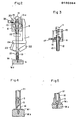
- the bit 21 When an absorption error or a screw feed error occurs, the bit 21 is intended to tighten non-screw to thereby lower the tip under the position shown in Fig. 2 and stops its descent upon abutting the lower end of joint 11 against a collar 20 on the block 13. Therefore, the microswitch 26 is restrained from operation in more than allowable stroke to prevent breakage of the same and also the tip of bit 21 from entering as drilling into the bore at work W 1 to damage it. In this case, however, the absorption pipe 18 is subjected to full pressure so that the work may have been broken by the pipe 18, or the pipe 18 itself is broken. Also, since the bit 21 comes out merely a little from the utmost end of absorption pipe 18, the screw tightening at the spot facing as shown in Fig. 5 and that at the flat surface as shown in Fig. 2 could not be performed by the same machine.
- the screw-driver 6 should be released from the driver- base 5, the driver 6 through the bit 21 be removed upwardly, and the bit screwed with the bit holder be ezchanged. Hence, the exchange of bit takes much time because the wiring for the driver need be refixed each time.
- the driver holding position is adjusted to optionally set the bit in position so that a distance between the utmost end of absorption pipe and the tip of bit therein is allowed to meet a length of one screw to be tightened, thereby absorbing always one screw only.
- a universal joint is provided with a through bore, through which a pin is inserted to thereby simply fix the bit holder, thereby enabling exchange of screw-driver without removal thereof.
- the bit enters at its tip into the threaded bore to lower more than usual, but the lowering of bit is detected to indicate an error of no screw.
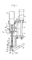
- reference A designates a lifting unit
- B designates a driver unit
- C designates catcher unit
- D designates escapement unit
- B designates a screw feed unit, so that screws fed in line therewith are caught by the catcher unit C and absorbed to be held by the driver unit B lowering from the lifting unit A, thereby being screw-tightened.
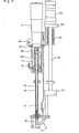
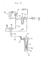
- Reference numeral 27 designates a fixed frame, on which a piping plate 28 is erected and at the upper portion thereof is fixed a cylinder base 29, 30 designates an air cylinder, which ia fixed to the cylinder base 29, the descent pressure of air cylinder 30 being adjustable by an air regulator 31 and the descent speed of the same adjustable by an exhaust air throttle valve 32, 33 designates a elide shaft fixed at both ends to the fixed frame 27 and cylinder base 29 respectively, 34 designates a slider connecting with the cylinder 30 and slidable on the slide shaft 33, 6 designates a driver held to the slider 34 in relation of being mounted desirably in position on the axis thereof, 35 designates a universal joint, which connects the driver 6 with the bit holder 10 and has a bore 35a perforating the joint 35 perpendicularly to the axis thereof, 21 designates a bit screwably connected to the utmost end of bit holder 10, 36 designates an external cylinder fixed to the slider 34 through
- a starting signal energizes a solenoid valve 49 so that air enters to an air conduit 50 from an air compressor 51 to thereby lower the driver unit B.
- air also enters into an air conduit 52 so as to be taken into the utmost end of absorption pipe by the vacuum generator 48 of an ejector system, thereby absorbing the screw stationary at the catcher 23, the screw absorbed into the absorption pipe 18 engaging at its head with the bit 21 rotating within the pipe 18.
- a tightening finish signal stops rotation of driver 6, the solenoid valve 49 is deenergized, the air compressor 51 communicates with an air conduit 53, and the driver unit rises, at which time the compressed air having used for lowering and remaining in the cylinder 30 is exhausted from the absorption pipe 18 via the air conduit 50, solenoid valve 49, air conduit 54, vacuum generator 48, vacuum filter 55, air conduit 56 and vacuum pipe 12.
- the vacuum generator 48 is restrained rapidly from absorption and dust or the like absorbed is discharged, especially fine particles attached to the vacuum generator 48 being removed therefrom.
- the bit thrust relates so stability of tightening force.
- the pressure when too small in comparison with the tightening force, the bit is liable to disengage from the screw, thereby breaking down the head of screw not to engage with the bit.
- the pressure when the pressure is too large, the work may be deflected or broken, the screw may enter slantwise into the absorption pipe, or the tightening torque may be not stable.
- This embodiment eliminates the cushion portion from between the driver 6 of rotational drive source and the bit 21 so that the air cylinder 30 for lifting the driver unit receives thrust of bit 21 and the pressure for lowering the air cylinder 30 is optionally adjusted by the air regulator 31, thereby obtaining proper bit thrust.
- any adjustment is not required to tighten the screw in a desired height and with accuracy.
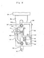
- the distance between the universal joint 35 and the male tapered block 13 is made larger than that between the utmost end of absorption pipe 18 and the tip of bit 21 and the microswitch 39, which detects the relative position of bit 21 to the absorption pipe 18, is usually turned on by the lever 41 and upon completing the screw-tightening, the lever 41 is adapted to leave the microswitch 39, and there is no fear of damaging the microswitch 39 even when the bit 21 with no screw comes largely out of the utmost end of absorption pipe 18.
- the screw-tightening is desirably performable not only for the flat surface but also for the spot facing where the absorption pipe 18 cannot enter therein and the bit 21 comes out largely from the utmost end thereof.
- Such function of tightening the screw at an optional height without any adjustment, on the plane surface, and at the spot facing, is largely effective in the case that a multi-point positioning apparatus, for example a XY table or the like, loading this screw-tightening machine carries out the screw-tightening under various conditions.
- the bit 21 when the bit with no screw screws forward, the bit 21, as shown in Fig. 10, enters the threaded bore at the work W to thereby lower more than usual screw-tightening, whereby the lever 41 swings largely by the coupler 47 in the direction of the arrow H to turn off the microswitch 39 and the lever 44 also swings to turn off the microswitch 40 which is usually on by the lever 44.
- the turn-off of microswitch 40 detects no screw, the bit 21 immediately stops its rotation to lift the driver unit, thereby enabling elimination of damage to the work and of a waste of time.
- a pin 57 is inserted through the through-bore 36a at the external cylinder 36 and through-bore 35a at the universal joint 35 to thereby block rotation of bit holder 10 and lower the head, loosen and remove the absorption pipe 18 coupled with the vacuum pipe 12, and turn the bit 21 by a monkey wrench or the like to release its screw-coupling with the bit holder 10.
- a monkey wrench or the like can often mount or dismount the bit necessary for erchange.
Landscapes
- Engineering & Computer Science (AREA)
- Mechanical Engineering (AREA)
- Details Of Spanners, Wrenches, And Screw Drivers And Accessories (AREA)
Applications Claiming Priority (1)
| Application Number | Priority Date | Filing Date | Title |
|---|---|---|---|
| PCT/JP1981/000412 WO1983002246A1 (fr) | 1981-12-25 | 1981-12-25 | Machine de vissage automatique du type retenant la vis par depression |
Publications (3)
| Publication Number | Publication Date |
|---|---|
| EP0100364A1 true EP0100364A1 (de) | 1984-02-15 |
| EP0100364A4 EP0100364A4 (de) | 1984-05-29 |
| EP0100364B1 EP0100364B1 (de) | 1986-12-10 |
Family
ID=13734357
Family Applications (1)
| Application Number | Title | Priority Date | Filing Date |
|---|---|---|---|
| EP19820900142 Expired EP0100364B1 (de) | 1981-12-25 | 1981-12-25 | Automatische schraubmaschine des die schraube mit unterdruck haltenden typs |
Country Status (3)
| Country | Link |
|---|---|
| EP (1) | EP0100364B1 (de) |
| DE (1) | DE3175698D1 (de) |
| WO (1) | WO1983002246A1 (de) |
Cited By (8)
| Publication number | Priority date | Publication date | Assignee | Title |
|---|---|---|---|---|
| EP0414277A1 (de) * | 1989-08-25 | 1991-02-27 | Katsuyuki Totsu | Automatischer Schraubendreher und Kontrollverfahren |
| GB2355423A (en) * | 1999-05-26 | 2001-04-25 | Koito Mfg Co Ltd | Method of and device for fastening body and lens of a vehicular light |
| CN102935588A (zh) * | 2012-11-23 | 2013-02-20 | 大连运明自动化技术有限公司 | 自动供钉万向型高速智能紧固机 |
| CN102941470A (zh) * | 2012-11-23 | 2013-02-27 | 大连运明自动化技术有限公司 | 万向型高速智能自动螺钉紧固机构 |
| CN102975011A (zh) * | 2012-11-23 | 2013-03-20 | 大连运明自动化技术有限公司 | 真空吸取式高速智能自动螺钉紧固机构 |
| CN103659255A (zh) * | 2013-12-11 | 2014-03-26 | 大连运明自动化技术有限公司 | 高速智能化横向紧固装配平台 |
| CN103894819A (zh) * | 2014-04-10 | 2014-07-02 | 天广消防股份有限公司 | 一种工件组合自动套丝机 |
| WO2020002116A1 (en) * | 2018-06-29 | 2020-01-02 | Atlas Copco Industrial Technique Ab | Sealing arrangement for a tightening tool |
Families Citing this family (7)
| Publication number | Priority date | Publication date | Assignee | Title |
|---|---|---|---|---|
| US7708429B2 (en) | 2006-07-21 | 2010-05-04 | Gregory Kennedy | Illuminated document display system |
| JP5513964B2 (ja) * | 2010-04-19 | 2014-06-04 | 株式会社大武ルート工業 | 自動ネジ締め装置 |
| CN102350630A (zh) * | 2011-11-08 | 2012-02-15 | 天津通广集团专用设备有限公司 | 螺钉自动装配机 |
| US10105829B2 (en) | 2013-11-08 | 2018-10-23 | Atlas Copco Industrial Technique Ab | Vacuum adapter for a power tool |
| CN104259843A (zh) * | 2014-09-24 | 2015-01-07 | 苏州石丸英合精密机械有限公司 | 全自动锁螺丝机的垂直式自动上料锁螺丝装置 |
| JP6114811B1 (ja) * | 2015-12-18 | 2017-04-12 | 日東精工株式会社 | ねじ締め機 |
| CN112192200A (zh) * | 2020-10-30 | 2021-01-08 | 浙江欧凯车业有限公司 | 一种滑板车组装用自动锁螺丝装置 |
Family Cites Families (1)
| Publication number | Priority date | Publication date | Assignee | Title |
|---|---|---|---|---|
| JPS5819430B2 (ja) * | 1979-01-08 | 1983-04-18 | 松下電器産業株式会社 | 真空吸着式自動ねじ締め機 |
-
1981
- 1981-12-25 DE DE8282900142T patent/DE3175698D1/de not_active Expired
- 1981-12-25 EP EP19820900142 patent/EP0100364B1/de not_active Expired
- 1981-12-25 WO PCT/JP1981/000412 patent/WO1983002246A1/ja not_active Ceased
Cited By (13)
| Publication number | Priority date | Publication date | Assignee | Title |
|---|---|---|---|---|
| EP0414277A1 (de) * | 1989-08-25 | 1991-02-27 | Katsuyuki Totsu | Automatischer Schraubendreher und Kontrollverfahren |
| GB2355423A (en) * | 1999-05-26 | 2001-04-25 | Koito Mfg Co Ltd | Method of and device for fastening body and lens of a vehicular light |
| GB2355423B (en) * | 1999-05-26 | 2001-08-22 | Koito Mfg Co Ltd | Fastening body and lens of vehicular light |
| US6502971B1 (en) | 1999-05-26 | 2003-01-07 | Koito Manufacturing Co., Ltd. | Method and device for fastening screw between body and lens of vehicular lighting device |
| CN102935588A (zh) * | 2012-11-23 | 2013-02-20 | 大连运明自动化技术有限公司 | 自动供钉万向型高速智能紧固机 |
| CN102941470A (zh) * | 2012-11-23 | 2013-02-27 | 大连运明自动化技术有限公司 | 万向型高速智能自动螺钉紧固机构 |
| CN102975011A (zh) * | 2012-11-23 | 2013-03-20 | 大连运明自动化技术有限公司 | 真空吸取式高速智能自动螺钉紧固机构 |
| CN103659255A (zh) * | 2013-12-11 | 2014-03-26 | 大连运明自动化技术有限公司 | 高速智能化横向紧固装配平台 |
| CN103894819A (zh) * | 2014-04-10 | 2014-07-02 | 天广消防股份有限公司 | 一种工件组合自动套丝机 |
| CN103894819B (zh) * | 2014-04-10 | 2016-06-01 | 天广消防股份有限公司 | 一种工件组合自动套丝机 |
| WO2020002116A1 (en) * | 2018-06-29 | 2020-01-02 | Atlas Copco Industrial Technique Ab | Sealing arrangement for a tightening tool |
| KR20210025629A (ko) * | 2018-06-29 | 2021-03-09 | 아틀라스 콥코 인더스트리얼 테크니크 에이비 | 조임 공구를 위한 밀봉 장치 |
| US11590643B2 (en) | 2018-06-29 | 2023-02-28 | Atlas Copco Industrial Technique Ab | Sealing arrangement for a tightening tool |
Also Published As
| Publication number | Publication date |
|---|---|
| DE3175698D1 (en) | 1987-01-22 |
| WO1983002246A1 (fr) | 1983-07-07 |
| EP0100364A4 (de) | 1984-05-29 |
| EP0100364B1 (de) | 1986-12-10 |
Similar Documents
| Publication | Publication Date | Title |
|---|---|---|
| EP0100364B1 (de) | Automatische schraubmaschine des die schraube mit unterdruck haltenden typs | |
| US4901431A (en) | Powered fastener installation apparatus | |
| US5036576A (en) | Method of installing a fastener | |
| JPS58110147A (ja) | リベツト締め装置 | |
| US7685700B2 (en) | Compensating unit for a tool unit and method for inserting an element into a workpiece | |
| EP4512575A1 (de) | Schaftverriegelungshülse und werkzeugmagazin | |
| JP2945848B2 (ja) | 分注装置 | |
| US4792655A (en) | Stud welding system feeding device | |
| JPH06218640A (ja) | 吸着保持式ネジ締装置 | |
| JPH06218607A (ja) | 主軸装置 | |
| JP2002178231A (ja) | 部品の自動締結装置 | |
| JP2005169512A (ja) | 自動ねじ締め装置 | |
| JPH10328951A (ja) | 円錐体の締着装置 | |
| JP2823651B2 (ja) | ねじ締め機 | |
| JP2682229B2 (ja) | ボルト供給装置 | |
| JP2811532B2 (ja) | 水平ねじ締め機 | |
| JPS6099531A (ja) | 部品供給装置 | |
| JPWO1983002246A1 (ja) | 真空吸着式自動ねじ締め機 | |
| JPH0111400Y2 (de) | ||
| JPS58120437A (ja) | ねじ部品の締付け方法及びその装置 | |
| JP2881370B2 (ja) | 風車供給釘打ち機 | |
| JPH0321864Y2 (de) | ||
| JP7393243B2 (ja) | ねじ締め機 | |
| JP2000079522A (ja) | ねじ締め装置 | |
| JP2535196Y2 (ja) | 近接センサ |
Legal Events
| Date | Code | Title | Description |
|---|---|---|---|
| PUAI | Public reference made under article 153(3) epc to a published international application that has entered the european phase |
Free format text: ORIGINAL CODE: 0009012 |
|
| 17P | Request for examination filed |
Effective date: 19830826 |
|
| AK | Designated contracting states |
Kind code of ref document: A1 Designated state(s): DE FR GB |
|
| GRAA | (expected) grant |
Free format text: ORIGINAL CODE: 0009210 |
|
| AK | Designated contracting states |
Kind code of ref document: B1 Designated state(s): DE FR GB |
|
| ET | Fr: translation filed | ||
| REF | Corresponds to: |
Ref document number: 3175698 Country of ref document: DE Date of ref document: 19870122 |
|
| PLBE | No opposition filed within time limit |
Free format text: ORIGINAL CODE: 0009261 |
|
| STAA | Information on the status of an ep patent application or granted ep patent |
Free format text: STATUS: NO OPPOSITION FILED WITHIN TIME LIMIT |
|
| 26N | No opposition filed | ||
| REG | Reference to a national code |
Ref country code: GB Ref legal event code: 746 Effective date: 19970901 |
|
| PGFP | Annual fee paid to national office [announced via postgrant information from national office to epo] |
Ref country code: FR Payment date: 19991208 Year of fee payment: 19 |
|
| PGFP | Annual fee paid to national office [announced via postgrant information from national office to epo] |
Ref country code: GB Payment date: 19991222 Year of fee payment: 19 |
|
| PGFP | Annual fee paid to national office [announced via postgrant information from national office to epo] |
Ref country code: DE Payment date: 19991230 Year of fee payment: 19 |
|
| PG25 | Lapsed in a contracting state [announced via postgrant information from national office to epo] |
Ref country code: GB Free format text: LAPSE BECAUSE OF NON-PAYMENT OF DUE FEES Effective date: 20001225 |
|
| GBPC | Gb: european patent ceased through non-payment of renewal fee |
Effective date: 20001225 |
|
| PG25 | Lapsed in a contracting state [announced via postgrant information from national office to epo] |
Ref country code: FR Free format text: LAPSE BECAUSE OF NON-PAYMENT OF DUE FEES Effective date: 20010831 |
|
| REG | Reference to a national code |
Ref country code: FR Ref legal event code: ST |
|
| PG25 | Lapsed in a contracting state [announced via postgrant information from national office to epo] |
Ref country code: DE Free format text: LAPSE BECAUSE OF NON-PAYMENT OF DUE FEES Effective date: 20011002 |