EP0100547A1 - Vorrichtung zur Steuerung der Abgasemission für Dieselmotoren - Google Patents
Vorrichtung zur Steuerung der Abgasemission für Dieselmotoren Download PDFInfo
- Publication number
- EP0100547A1 EP0100547A1 EP83107563A EP83107563A EP0100547A1 EP 0100547 A1 EP0100547 A1 EP 0100547A1 EP 83107563 A EP83107563 A EP 83107563A EP 83107563 A EP83107563 A EP 83107563A EP 0100547 A1 EP0100547 A1 EP 0100547A1
- Authority
- EP
- European Patent Office
- Prior art keywords
- trap
- exhaust
- burner
- emission control
- control device
- Prior art date
- Legal status (The legal status is an assumption and is not a legal conclusion. Google has not performed a legal analysis and makes no representation as to the accuracy of the status listed.)
- Withdrawn
Links
Images
Classifications
-
- F—MECHANICAL ENGINEERING; LIGHTING; HEATING; WEAPONS; BLASTING
- F01—MACHINES OR ENGINES IN GENERAL; ENGINE PLANTS IN GENERAL; STEAM ENGINES
- F01N—GAS-FLOW SILENCERS OR EXHAUST APPARATUS FOR MACHINES OR ENGINES IN GENERAL; GAS-FLOW SILENCERS OR EXHAUST APPARATUS FOR INTERNAL-COMBUSTION ENGINES
- F01N3/00—Exhaust or silencing apparatus having means for purifying, rendering innocuous, or otherwise treating exhaust
- F01N3/02—Exhaust or silencing apparatus having means for purifying, rendering innocuous, or otherwise treating exhaust for cooling, or for removing solid constituents of, exhaust
-
- F—MECHANICAL ENGINEERING; LIGHTING; HEATING; WEAPONS; BLASTING
- F01—MACHINES OR ENGINES IN GENERAL; ENGINE PLANTS IN GENERAL; STEAM ENGINES
- F01N—GAS-FLOW SILENCERS OR EXHAUST APPARATUS FOR MACHINES OR ENGINES IN GENERAL; GAS-FLOW SILENCERS OR EXHAUST APPARATUS FOR INTERNAL-COMBUSTION ENGINES
- F01N3/00—Exhaust or silencing apparatus having means for purifying, rendering innocuous, or otherwise treating exhaust
- F01N3/02—Exhaust or silencing apparatus having means for purifying, rendering innocuous, or otherwise treating exhaust for cooling, or for removing solid constituents of, exhaust
- F01N3/021—Exhaust or silencing apparatus having means for purifying, rendering innocuous, or otherwise treating exhaust for cooling, or for removing solid constituents of, exhaust by means of filters
- F01N3/023—Exhaust or silencing apparatus having means for purifying, rendering innocuous, or otherwise treating exhaust for cooling, or for removing solid constituents of, exhaust by means of filters using means for regenerating the filters, e.g. by burning trapped particles
- F01N3/025—Exhaust or silencing apparatus having means for purifying, rendering innocuous, or otherwise treating exhaust for cooling, or for removing solid constituents of, exhaust by means of filters using means for regenerating the filters, e.g. by burning trapped particles using fuel burner or by adding fuel to exhaust
- F01N3/0253—Exhaust or silencing apparatus having means for purifying, rendering innocuous, or otherwise treating exhaust for cooling, or for removing solid constituents of, exhaust by means of filters using means for regenerating the filters, e.g. by burning trapped particles using fuel burner or by adding fuel to exhaust adding fuel to exhaust gases
- F01N3/0256—Exhaust or silencing apparatus having means for purifying, rendering innocuous, or otherwise treating exhaust for cooling, or for removing solid constituents of, exhaust by means of filters using means for regenerating the filters, e.g. by burning trapped particles using fuel burner or by adding fuel to exhaust adding fuel to exhaust gases the fuel being ignited by electrical means
-
- F—MECHANICAL ENGINEERING; LIGHTING; HEATING; WEAPONS; BLASTING
- F02—COMBUSTION ENGINES; HOT-GAS OR COMBUSTION-PRODUCT ENGINE PLANTS
- F02B—INTERNAL-COMBUSTION PISTON ENGINES; COMBUSTION ENGINES IN GENERAL
- F02B3/00—Engines characterised by air compression and subsequent fuel addition
- F02B3/06—Engines characterised by air compression and subsequent fuel addition with compression ignition
-
- Y—GENERAL TAGGING OF NEW TECHNOLOGICAL DEVELOPMENTS; GENERAL TAGGING OF CROSS-SECTIONAL TECHNOLOGIES SPANNING OVER SEVERAL SECTIONS OF THE IPC; TECHNICAL SUBJECTS COVERED BY FORMER USPC CROSS-REFERENCE ART COLLECTIONS [XRACs] AND DIGESTS
- Y10—TECHNICAL SUBJECTS COVERED BY FORMER USPC
- Y10S—TECHNICAL SUBJECTS COVERED BY FORMER USPC CROSS-REFERENCE ART COLLECTIONS [XRACs] AND DIGESTS
- Y10S55/00—Gas separation
- Y10S55/10—Residue burned
-
- Y—GENERAL TAGGING OF NEW TECHNOLOGICAL DEVELOPMENTS; GENERAL TAGGING OF CROSS-SECTIONAL TECHNOLOGIES SPANNING OVER SEVERAL SECTIONS OF THE IPC; TECHNICAL SUBJECTS COVERED BY FORMER USPC CROSS-REFERENCE ART COLLECTIONS [XRACs] AND DIGESTS
- Y10—TECHNICAL SUBJECTS COVERED BY FORMER USPC
- Y10S—TECHNICAL SUBJECTS COVERED BY FORMER USPC CROSS-REFERENCE ART COLLECTIONS [XRACs] AND DIGESTS
- Y10S55/00—Gas separation
- Y10S55/30—Exhaust treatment
Definitions
- the present invention relates to an exhaust emission control device for Diesel engines and more particularly to an exhaust emission control device for Diesel engines in which particulates in the exhaust gas from a Diesel engine are collected on a trap and oxidized using a burner to regenerate the trap.
- k A exp(-AE/RT). It will be clear from the equation that the oxidation rate depends upon only temperature. Accordingly, in order to oxidize particulates with high efficiency, it is necessary to rapidly raise the atmospheric temperature of the collected particulates. In the conventional device having the above-described construction, however, since the flames from the burner are applied only from the trap inlet front surface, the heat-receiving area of the trap is small, so that it is impossible to obtain a uniform temperature rise throughout the trap.
- the combustion condition of the burner is affected by the flow rate of the exhaust gas, the exhaust pressure, the amount of 0 2 in the exhaust gas and so forth, which largely vary according to the engine operating conditions. Therefore, it is extremely difficult to effect control so that the burner will perform a complete combustion at all times.
- an exhaust emission control device for Diesel engines comprising: a trap disposed in an exhaust pipe connected to an exhaust manifold; and a trap-heating burner disposed outside the exhaust pipe, whereby a combustion gas from the burner is led to the outer . peripheral portion of the trap to heat the same.
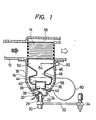
- FIG. 1 is a sectional view of an embodiment of an exhaust emission control device in accordance with the invention, .
- an exhaust pipe 12 is provided with a trap 14 for collecting particulates.
- the trap 14 fitted in the exhaust pipe 12 is generally a ceramic honeycomb trap. When the exhaust gas passes through the honeycomb trap 14, particulates are trapped at porous walls thereof.
- a burner 16 is secured to the side of the exhaust pipe 12 having the trap 14 fitted therein.
- the burner 16 has a nozzle 22 secured through a nozzle holder 20 to the end portion of a burner casing 18 secured to the exhaust pipe 12.
- a nozzle port 26 of the nozzle 22 is inserted into an ignition chamber 24 defined by the nozzle holder 20, and an ignition electrode 28 is provided in front of the nozzle port 26.
- the nozzle 22 is provided with a solenoid valve 30 so that the fuel pumped from a fuel pump 34 through a pipe 32 can be cut off when the burner 16 is turned off.
- a first partition member 36 is fixed in the burner casing 18 in front of the nozzle port 26, and a throttle portion 38 is formed on the side of the substantially speaker-shaped first partition member 36 closer to the nozzle (on the upstream side).
- the first partition member 36 has a diffusion plate 40 provided in the central portion. thereof, so that the space inside the first partition member 36 is divided by the diffusion plate 40 into a gasifying chamber 42 and a mixing chamber 44 on the upstream and downstream sides thereof, respectively.
- the downstream-side end of the first partition member 36 is connected to the upstream-side end of a second partition member 46, and the dowstream-side of a throttle portion 48 formed on the second partition member 46 is defined as a combustion chamber 50, into which a detecting portion 54 of a flame detector 52 secured to the burner casing 18 is inserted.
- a gas flow passage 56 is formed extending from the combustion chamber 50 so as to surround the peripheray of the trap 14.
- a casing air vent 58 is formed in a portion of the burner casing 18 corresponding to the side of the first partition member 36 so that the air from a blower 60 can be introduced into the burner 16.
- the nozzle 22 measures the fuel pressurized by the fuel pump 34 and jets out the fuel being atomized from the nozzle port 26 into the ignition chamber 24.
- the atomized fuel in the ignition chamber 24 is ignited by means of a spark generated by the ignition electrode 28.
- the fuel is gasified by the red-hot diffusion plate 40 and sent into the mixing chamber 44.
- the fuel entering the mixing chamber 44 is accelerated in gasification by the second partition member as well as mixed with the air supplied from the blower 60. Thereafter, the fuel which is gasified and mixed with the air enters the combustion chamber 50 to burn being supplied with air necessary for combustion.
- the combustion gas of the fuel thus completely burned in the burner 16 is discharged to the outside through the gas flow passage 56 provided around the trap 14.
- the combustion of fuel by the burner 16 can be conducted without being adversely affected by the pressure and exhaust pulsation in the exhaust pipe, chemical components in the exhaust gas and so forth.
- the combustion gas from the burner 16 to. the periphery of the trap 14, it is possible to make the trap 14 high in temperature under a stable state.
- the burner can be installed without requiring any large modification of the exhaust manifold and the like.
- the combustion gas may be introduced into the exhaust pipe 12.
- the combustion of fuel by the burner is controlled in consideration of that the increase in ventilation resistance of the trap due to the increase in amount of the collected particulates, i.e., the pressure loss in the trap rapidly enlarges as the engine operating time becomes longer, and that as the engine speed is higher, or the engine load is larger, the temperature of the exhaust gas itself becomes higher and the trap temperature rises, so that the particulates are oxidized without being heated by the burner particularly.
- the rate of change of the . trap pressure loss with the changes of the engine speed and the engine load is experimentally obtained and previously fed into a controller.
- the pressure loss is calculated from an actual engine speed and engine load according to the change rate, and when the pressure loss exceeds any desired set level, the burner 16 is actuated. Since the trap temperature and the trap regeneration time are inversely proportional to each other regardless of the size of the trap, it is only necessary to arrange such that the trap temperature during the operation of the burner is detected, and the operating time of the burner can be automatically set by the controller according to the detected trap temperature.
Landscapes
- Engineering & Computer Science (AREA)
- Chemical & Material Sciences (AREA)
- Combustion & Propulsion (AREA)
- Mechanical Engineering (AREA)
- General Engineering & Computer Science (AREA)
- Processes For Solid Components From Exhaust (AREA)
- Exhaust Gas After Treatment (AREA)
- Filtering Of Dispersed Particles In Gases (AREA)
Applications Claiming Priority (2)
| Application Number | Priority Date | Filing Date | Title |
|---|---|---|---|
| JP57133690A JPS5925024A (ja) | 1982-08-02 | 1982-08-02 | デイ−ゼルエンジンの排気浄化装置 |
| JP133690/82 | 1982-08-02 |
Publications (1)
| Publication Number | Publication Date |
|---|---|
| EP0100547A1 true EP0100547A1 (de) | 1984-02-15 |
Family
ID=15110594
Family Applications (1)
| Application Number | Title | Priority Date | Filing Date |
|---|---|---|---|
| EP83107563A Withdrawn EP0100547A1 (de) | 1982-08-02 | 1983-08-01 | Vorrichtung zur Steuerung der Abgasemission für Dieselmotoren |
Country Status (4)
| Country | Link |
|---|---|
| US (1) | US4506506A (de) |
| EP (1) | EP0100547A1 (de) |
| JP (1) | JPS5925024A (de) |
| KR (1) | KR840006038A (de) |
Cited By (4)
| Publication number | Priority date | Publication date | Assignee | Title |
|---|---|---|---|---|
| EP0202344A1 (de) * | 1984-03-28 | 1986-11-26 | Gerhard Richter | Vorrichtung zur Wärmeentziehung aus den Auspuffgasen eines Verbrennungsmotors |
| EP0331795A1 (de) * | 1988-03-09 | 1989-09-13 | Webasto AG Fahrzeugtechnik | Mit Abgasen einer Brennkraftmaschine betriebener Brenner |
| EP0454351A3 (de) * | 1990-04-27 | 1991-12-18 | Lucas Industries Public Limited Company | Brennervorrichtung |
| EP0585752A1 (de) * | 1992-09-01 | 1994-03-09 | Pierburg Gmbh | Abgasreinigungseinrichtung für Diesel-Brennkraftmaschinen |
Families Citing this family (11)
| Publication number | Priority date | Publication date | Assignee | Title |
|---|---|---|---|---|
| JPS5842754A (ja) * | 1981-09-04 | 1983-03-12 | Kobe Steel Ltd | 耐熱性の優れたばね用鋼 |
| JPS6013914A (ja) * | 1983-07-04 | 1985-01-24 | Mitsubishi Electric Corp | デイ−ゼルパテイキユレ−ト浄化装置 |
| DE3504737A1 (de) * | 1985-02-12 | 1986-08-14 | Bayerische Motoren Werke AG, 8000 München | Vorrichtung und verfahren zum beseitigen von russ o.dgl. aus den abgasen einer brennkraftmaschine |
| DE3545437A1 (de) * | 1985-12-20 | 1987-07-02 | Eberspaecher J | Abgasreinigungsvorrichtung fuer dieselmotoren |
| JP3226207B2 (ja) * | 1996-05-24 | 2001-11-05 | 日野自動車株式会社 | 排気黒煙除去装置の微粒子焼却方法及び機構 |
| WO2006137694A1 (en) * | 2005-06-22 | 2006-12-28 | Korea Institute Of Machinery And Materials | Burner for regeneration of diesel engine particulate filter and diesel engine particulate filter having the same |
| KR100542803B1 (ko) * | 2005-06-22 | 2006-01-11 | 한국기계연구원 | 디젤엔진매연여과장치 재생용 버너 |
| KR100548451B1 (ko) * | 2005-07-22 | 2006-01-31 | 한국기계연구원 | 디젤엔진매연여과장치 재생용 내염버너 |
| EP1960639B1 (de) | 2006-08-01 | 2015-06-17 | Korea Institute Of Machinery & Materials | Reduktionssystem von teilchen in abgasen |
| KR100692948B1 (ko) | 2006-08-01 | 2007-03-12 | 한국기계연구원 | Dpf시스템에서의 플라즈마 반응기를 이용한 pm저감방법 |
| US10375901B2 (en) | 2014-12-09 | 2019-08-13 | Mtd Products Inc | Blower/vacuum |
Citations (3)
| Publication number | Priority date | Publication date | Assignee | Title |
|---|---|---|---|---|
| GB1270782A (en) * | 1970-02-02 | 1972-04-12 | Inst Gornogo Dela Sibirskogo O | Apparatus for purifying engine exhaust gases |
| FR2396163A1 (fr) * | 1977-06-30 | 1979-01-26 | Texaco Development Corp | Filtre de fumee pour moteur a combustion interne |
| GB2013103A (en) * | 1978-01-26 | 1979-08-08 | Gen Motors Corp | Diesel engine exhaust cleaner and burner |
Family Cites Families (3)
| Publication number | Priority date | Publication date | Assignee | Title |
|---|---|---|---|---|
| US3732696A (en) * | 1970-06-02 | 1973-05-15 | Nissan Motor | Vehicular air-pollution preventive |
| JPS5415973B2 (de) * | 1972-05-08 | 1979-06-19 | ||
| US4345431A (en) * | 1980-03-25 | 1982-08-24 | Shimizu Construction Co. Ltd. | Exhaust gas cleaning system for diesel engines |
-
1982
- 1982-08-02 JP JP57133690A patent/JPS5925024A/ja active Pending
-
1983
- 1983-07-27 US US06/517,817 patent/US4506506A/en not_active Expired - Lifetime
- 1983-07-29 KR KR1019830003549A patent/KR840006038A/ko not_active Withdrawn
- 1983-08-01 EP EP83107563A patent/EP0100547A1/de not_active Withdrawn
Patent Citations (3)
| Publication number | Priority date | Publication date | Assignee | Title |
|---|---|---|---|---|
| GB1270782A (en) * | 1970-02-02 | 1972-04-12 | Inst Gornogo Dela Sibirskogo O | Apparatus for purifying engine exhaust gases |
| FR2396163A1 (fr) * | 1977-06-30 | 1979-01-26 | Texaco Development Corp | Filtre de fumee pour moteur a combustion interne |
| GB2013103A (en) * | 1978-01-26 | 1979-08-08 | Gen Motors Corp | Diesel engine exhaust cleaner and burner |
Cited By (4)
| Publication number | Priority date | Publication date | Assignee | Title |
|---|---|---|---|---|
| EP0202344A1 (de) * | 1984-03-28 | 1986-11-26 | Gerhard Richter | Vorrichtung zur Wärmeentziehung aus den Auspuffgasen eines Verbrennungsmotors |
| EP0331795A1 (de) * | 1988-03-09 | 1989-09-13 | Webasto AG Fahrzeugtechnik | Mit Abgasen einer Brennkraftmaschine betriebener Brenner |
| EP0454351A3 (de) * | 1990-04-27 | 1991-12-18 | Lucas Industries Public Limited Company | Brennervorrichtung |
| EP0585752A1 (de) * | 1992-09-01 | 1994-03-09 | Pierburg Gmbh | Abgasreinigungseinrichtung für Diesel-Brennkraftmaschinen |
Also Published As
| Publication number | Publication date |
|---|---|
| JPS5925024A (ja) | 1984-02-08 |
| US4506506A (en) | 1985-03-26 |
| KR840006038A (ko) | 1984-11-21 |
Similar Documents
| Publication | Publication Date | Title |
|---|---|---|
| US4506506A (en) | Exhaust emission control device for diesel engine | |
| JPS6141944Y2 (de) | ||
| US4383411A (en) | Diesel exhaust cleaner with burner vortex chamber | |
| US4662172A (en) | Exhaust purification apparatus | |
| US4167852A (en) | Diesel engine exhaust cleaner and burner | |
| US4502278A (en) | Diesel exhaust cleaner and burner system with multi-point igniters | |
| JPS6359013B2 (de) | ||
| US4494375A (en) | Filtration system for diesel engine exhaust-I | |
| US4299600A (en) | Trapper device for collecting and incinerating fine particulates included in exhaust gas from a diesel engine | |
| CA1296265C (en) | Apparatus for regeneration of a particulate filter in diesel engine | |
| JPS56124653A (en) | Carbon particle removing apparatus for internal combustion engine | |
| US3802194A (en) | Exhaust gas cleaning device | |
| US8424291B2 (en) | Flame glow plug | |
| US3209532A (en) | Afterburner and muffler device | |
| GB2260279A (en) | Catalytic converter | |
| US3059421A (en) | Apparatus for minimizing the combustible content of exhaust gases | |
| US3978836A (en) | Suction heat control unit in internal combustion engine | |
| EP0165922B1 (de) | Regeneriersystem für abtrennfilter mit mittel zum umleiten der auspuffgase | |
| US3991567A (en) | Vortical flow exhaust gas reactor | |
| JPS6141945Y2 (de) | ||
| KR19990032947U (ko) | 디젤자동차용 배기가스정화장치의 연소기 | |
| JPH04151406A (ja) | 超音波霧化装置付燃焼装置 | |
| JPH0122448B2 (de) | ||
| JPS5929718A (ja) | パテイキユレ−トフイルタの再生用バ−ナ | |
| JPH0137136Y2 (de) |
Legal Events
| Date | Code | Title | Description |
|---|---|---|---|
| PUAI | Public reference made under article 153(3) epc to a published international application that has entered the european phase |
Free format text: ORIGINAL CODE: 0009012 |
|
| 17P | Request for examination filed |
Effective date: 19830803 |
|
| AK | Designated contracting states |
Designated state(s): DE FR GB IT SE |
|
| STAA | Information on the status of an ep patent application or granted ep patent |
Free format text: STATUS: THE APPLICATION HAS BEEN WITHDRAWN |
|
| 18W | Application withdrawn |
Withdrawal date: 19850814 |
|
| RIN1 | Information on inventor provided before grant (corrected) |
Inventor name: USUI, TOSHIFUMI Inventor name: YANAGISAWA, SYOZO |