EP0100719A1 - Schusssimulationsgerät zum Training mit Schulterwaffen - Google Patents
Schusssimulationsgerät zum Training mit Schulterwaffen Download PDFInfo
- Publication number
- EP0100719A1 EP0100719A1 EP83401526A EP83401526A EP0100719A1 EP 0100719 A1 EP0100719 A1 EP 0100719A1 EP 83401526 A EP83401526 A EP 83401526A EP 83401526 A EP83401526 A EP 83401526A EP 0100719 A1 EP0100719 A1 EP 0100719A1
- Authority
- EP
- European Patent Office
- Prior art keywords
- target
- shooter
- instructor
- fictitious
- vision
- Prior art date
- Legal status (The legal status is an assumption and is not a legal conclusion. Google has not performed a legal analysis and makes no representation as to the accuracy of the status listed.)
- Granted
Links
- 238000004088 simulation Methods 0.000 title claims abstract description 16
- 230000003287 optical effect Effects 0.000 claims description 21
- 230000001960 triggered effect Effects 0.000 claims description 2
- 230000015572 biosynthetic process Effects 0.000 claims 1
- 238000006073 displacement reaction Methods 0.000 claims 1
- 238000010304 firing Methods 0.000 abstract description 11
- 235000015842 Hesperis Nutrition 0.000 abstract description 3
- 235000012633 Iberis amara Nutrition 0.000 abstract description 3
- 230000005693 optoelectronics Effects 0.000 description 6
- 238000004364 calculation method Methods 0.000 description 4
- 210000000056 organ Anatomy 0.000 description 4
- 230000009471 action Effects 0.000 description 1
- 238000010586 diagram Methods 0.000 description 1
- 230000004048 modification Effects 0.000 description 1
- 238000012986 modification Methods 0.000 description 1
- 230000004044 response Effects 0.000 description 1
- 230000008685 targeting Effects 0.000 description 1
Images



Classifications
-
- F—MECHANICAL ENGINEERING; LIGHTING; HEATING; WEAPONS; BLASTING
- F41—WEAPONS
- F41G—WEAPON SIGHTS; AIMING
- F41G3/00—Aiming or laying means
- F41G3/26—Teaching or practice apparatus for gun-aiming or gun-laying
- F41G3/2616—Teaching or practice apparatus for gun-aiming or gun-laying using a light emitting device
- F41G3/2622—Teaching or practice apparatus for gun-aiming or gun-laying using a light emitting device for simulating the firing of a gun or the trajectory of a projectile
- F41G3/2644—Displaying the trajectory or the impact point of a simulated projectile in the gunner's sight
Definitions
- the present invention relates to a simulation device intended for training in the maneuvering of shoulder weapons, such as those used for firing rockets or self-guided missiles, or in the maneuvering of similar weapons.
- Simulation devices for shooting training are already known and widely. widespread. They are used for training and instructing shooters by allowing them, indoors or on real ground, to practice aiming a weapon at a target, without actually making use of projectiles.
- the projectile is a fictitious projectile, a calculator of which makes it possible to define the position in order to compare it with that of the target and to assess the quality of the shot, in particular determining if the aiming is correct to drive the simulated projectile to an impact on the target .
- These simulation devices are constantly being perfected in order to reproduce the conditions of real shots as well as possible, so that the shooters are not disoriented when they go from training to shooting simulation with real projectiles.
- the present invention responds to the concern of better adapting fire simulation devices of the above type. above for training in the maneuvering of rocket launchers for self-guided missile launchers or similar weapons, allowing the operator to be placed in conditions very close to those he will encounter in live fire .
- the invention proposes to provide the simulation device with concealed means controlled to hide the field of vision of the shooter immediately after the shot, thus avoiding giving the shooter the annoying habit of staying put to see the result of his shot and thus being vulnerable to a possible response.
- the subject of the invention is therefore a simulation device for training in the maneuvering of shoulder or similar weapons, comprising a weapon with an aiming axis orientable by the shooter; provided with an optical unit presenting to the shooter's observation a field of vision comprising a shooting range and a target, and means for triggering a fictitious projectile shot by the shooter, means for transmitting an image of said field of vision at an instructor's station and project it onto a screen, and a computer functionally connected to the optical unit to determine the impact position of the projectile in the plane of the target, characterized in that it comprises means of occultation to eclipse the field of vision of the shooter's sight when the shooting is triggered, and means for visualizing the impact position relative to the target on the screen of the instructor station.
- the exercises are carried out on a shooting range in which there is a target, generally mobile.
- the device comprises means for forming a fictitious target appearing in the field of vision of the shooter superimposed on the shooting range.
- These means can be, for example, of the type described in the patent application filed by the applicant on June 12, 1981, under the number 81 11574. They make it possible to visualize a realistic representation in front of the shooter and the instructor :, no punctual, of an evolving target.
- the target is not necessarily unique and the invention applies equally well to exercises on multiple targets.
- the concealment means are advantageously constituted so that when it is a fictitious target, this target is found in the field of vision of the shooter at the same time as the shooting range, but so as to allow to remain this fictitious target on the instructor station screen when the shooter's field of vision is obscured.
- the instructor is thus able to assess the result of the shot based on the position occupied by the point of impact with respect to the fictitious target at the time when the fictitious projectile is supposed to reach the plane of the target. Only the shooting range disappears from his screen when the shooter starts shooting and he can still see the point of impact and the fictitious target which are embedded on his screen by electronic means controlled by the computer.
- the device makes available to the instructor an index target location, controllable from the instructor station and displayed on the corresponding screen.
- an index allows the instructor to pursue the target as long as it is visible in the projected image of the shooter's field of vision and then, after the launch of the shot and the occultation, to keep an indication of the position of the target by this index which remains visible on its screen.
- Figure 1 is an overview of a simulation device according to the invention used for training in firing rockets from a shoulder anti-tank weapon. This is illustrated by a single rocket launcher tube 6, although the device may include several, depending on the number of shooters to train in the same session. The particular case considered is not restrictive, either, as regards the type of weapon, the tube 6 being able more generally to be a projectile launcher and the projectile being able to be for example a missile as well as a rocket .
- an optical unit 1 which comprises two parts: an optoelectronic box 11 situated inside the launching tube and an optical box 12 placed in front of the telescope 13 of the shooter and fixed on the internal part of the optoelectronic box 11.
- a computer 3 comprising logic circuits based on microprocessors and analog interface circuits, makes it possible to manage the optical unit 1, as well as a control desk 21 and a video screen 22 which: constitute an instructor station 2 From this position, the instructor organizes the shooting exercises and assesses the results.
- a battery 4 supplies the supply current at a voltage of 27 V. It also includes electronic circuits which make it possible to recharge it from the network, or to supply the simulator directly from the network.
- connection cables 5 provide the necessary functional links between the computer and the various elements.
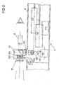
- FIG. 2 represents a top view of the optical unit 1 integrated in the tube 6.
- This optical unit 1 comprises various elements which have the function on the one hand of presenting to the shooter's observation, in the scope 13, a field of vision including the shooting range, with or without real target, a reticle materializing the line of sight, and possibly a fictitious target, on the other hand to take an image of this field of vision to transmit it to the post - instructor .
- a synthetic image generation device 111 makes it possible to produce fictitious target images under the control of the computer 3.
- This image generator in the particular case considered here, is of the flying cathode-ray tube type -spot as described in patent application number 81 11574 filed in the name of the Applicant on June 12, 1981.
- the successive target images produced on the tube are transmitted to the optical unit 12 and the telescope 13 by a prism with a semi-reflecting surface 122 and a semi-reflecting plate 121 of the optical unit 12, one like the other oriented at 45 degrees from the optical path ..
- a video camera 112 is arranged in the optoelectronic box 11, next to the image generator 111, so as to take the picture of the visible optical field of the shooter's scope 13, which is returned to it by the semi-reflecting blade 121 and a prism with a semi-reflecting surface 116.
- the image is retransmitted by the electronic equipment to be reproduced on the video screen 22 of the instructor station 2.
- the optoelectronic block also contains a gyroscope 113 which provides information to the computer on the movements which can be printed on the weapon during the operations, so that the computer can compensate for these movements in the calculations.
- a slope detector 114 also connected to the computer, makes it possible to correct the calculation of the impact point as a function of the slope.
- the semi-transparent blade 121 which is located in front of the lens of the telescope 13 and which makes it possible to transmit to the shooter the image of the landscape, by superimposing on it the reflected images coming from the generator d 'images 111. It also makes it possible to return all of these images, constituting the overall image of the shooter's field of vision, towards the video camera 112, through an automatically adjustable diaphragm 125.
- Two switchable gray filters 124 attenuate the brightness of the landscape.
- the shooter also sees in the scope 13 a reticle linked to the aiming axis of the weapon, which can either be engraved inside the scope or projected onto it by conventional optical means, or be produced by the image generator 111, under the control of the computer, and a fictitious target, generated by the device 111 and superimposed on the landscape.
- the optical unit also comprises, according to the invention, a concealing veil 123, actuated by a rotating electromagnet 126, which can be brought across the optical path to suppress the vision of the landscape in the telescope 13 after the simulated rocket departure.
- This movement of the web 123 is carried out under the command of an order which is issued from the computer at the time when the shooter triggers the firing by pressing the trigger of his weapon.
- this concealment device always leaves the sight of a person viewed by the telescope, the images coming from the image generator 111. Therefore, the arrangement shown is better suited if the target is a real target, which is then eclipsed with the landscape at the time of concealment by the veil 123.
- the veil is moved to be between the blade 121 and the telescope 13, so that the images from the generator 11, in particular those representing a fictitious target, are hidden from the view of the shooter at the same time as the landscape during the occultation.
- FIG. 2 shows a windscreen 127, disposed in front of the optical unit 12. It is useful in the case of indoor training. Indeed, while in the present description, we have rather referred to training outside, in front of a real shooting range, the same device can be used, under similar conditions, for indoor operation.
- the shooting range is then constituted by a landscape image projected into the shooter's field of vision. These may for example be still images projected from slides in the case where the target is a so-called fictitious target formed elsewhere, or images projected from a film depicting a moving target moving on a fixed ground, the operating mode then being that of a so-called real target training.
- this calculator receives information, mainly from the launching or triggering device of the shot 14, from a device for controlling the generation of a fictitious target 15, available to the instructor, and from a device index control 16 whose used will appear later. It also receives synchronization signals from an electronic video control unit 17, which manages the operation of the camera. 2 and ensures the summation of the video signals received from the. camera and computer to transmit them to the video monitor 18 controlling the display on the screen of the instructor station. More accessory bodies whose information is also involved in the calculations have not been shown.
- the computer issues orders, as has already been explained, mainly in the direction of the image generator 111, which has been represented with its cathode ray tube 19 and the very high voltage current supply thereof, and in the direction of the concealment device 23, which includes the web 123 and its drive motor 126. It also produces video overlay signals , which are transmitted to the electronic assembly 17 for the display of the corresponding information on the screen 22 of the instructor station. Finally, the computer 3 determines, mainly as a function of previously recorded characteristics of the simulated projectile, the distance from the target and the other parameters mentioned, what would be the point of impact of this projectile in the plane of the target.
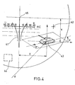
- FIG. 4 shows the indications which are displayed on the instructor's screen under the control of the overlay signals.
- the fictitious target 43 has appeared, which appears there, in the case of an operation with a fictitious target, retransmitted by the camera 112 of the image generator 111.
- the overlay signals contain the information necessary for the display of 'a reticle 41, identical to that which is presented to the viewer of the shooter and linked like him to the line of sight 45, with an index 44 that the instructor determines, in the form of a variable rectangle in position and in dimensions, in the case of operation with an actual target, and an impact cross 42 characterizing the position of the point of impact determined by the computer.
- a first part of the desk 21 allows the instructor, after power-up (controlled on the computer), to choose between three functions, depending on whether he presses an "initialization” key 211, a "dummy target” key 212, a "real target” key 213.
- the instructor first chooses the "initialization” key 211, because he must ensure that the harmonization of the origins is correct.
- the origins or axes of reference for the generation of a fictitious target and the video overlay of the aiming reticle must be confused with the origin of the reticle of the shooter's scope.
- the instructor uses zone 219 of the control console which allows him, by acting on the potentiometer buttons grouped by three, first to align on the reticle of the shooter's scope a reference cross generated by the simulator, centered on a reference axis, then align the crosshairs on the screen on the cross.
- the three potentiometers of each group allow this to move the corresponding image respectively in X, in Y and in rotation (fig. 4).
- a fictitious target mode of operation the instructor has part 218 of the desk, which allows him to record the parameters of several fictitious targets before the instruction sessions, namely for example, for each target: a reference number, the distance d from the target at its appearance, its speed, its orientation in space relative to the horizontal and vertical directions, its position in X and Y relative to the center of the field (always at the time of its appearance ), the slope of the terrain on which it operates, its brightness. It is also possible for him to modify the recorded linear trajectory of a given target, during exercise, by action in real time on a control stick 215 which makes it possible to modify the orientation of the target and to vary its speed. .
- Part 214 of the desk is used in conjunction with the control stick 215 when the instructor has chosen the operating mode on real target.
- the computer In this operating mode, the computer generates the rectangular index 44 on the video screen and the instructor brings this index superimposed on the target (which he observes on the landscape retransmitted by the camera) by means of the control stick 215
- potentiometers 216 and 217 At the same time, by acting on potentiometers 216 and 217 according to the height of the target and its width, it adjusts the size of the index so that it corresponds to the dimensions of the target.
- the instructor pursues the target until the start of the shot, which allows the computer to determine by the evolution of the magnitude, the position and the speed of the index, the distance, the position, the target's speed and direction of movement when the shot was fired.
- FIGS. 5a, 5b, 5c show in successive stages, on the left, what the shooter sees in the scope, on the right what appears on the instructor's screen.
- the instructor indicates to the shooter the position of appearance of the target (for example: tank at the edge of the grove on the right).
- the shooter prepares his weapon and directs it to the designated location.
- the instructor when he considers that the shooter is targeting the indicated area, decides to start the target, by causing the generation of a fictitious target whose parameters he has previously recorded (fig. 5a).
- a fictitious target whose parameters he has previously recorded (fig. 5a).
- a fictitious target whose parameters he has previously recorded
- the shooter points his weapon (fig. 5b)
- the instructor appreciates his work by means of the telescopic reticle reproduced on the video monitor.
- the shooter orders the firing of the fictitious rocket.
- the triggering of the shot instantly causes the movement of the concealment veil of the optical unit, which then obstructs the vision of the landscape for the shooter and the instructor, and even that of the fictitious target for the shooter in the case shown (fig. 5c
- the shooter then puts down his weapon and moves away, then joins the instructor in front of the video screen to assess the result of the shot. They can see the embedded reticle 41, the fictitious target 43, whose position is frozen at the moment of firing, increased by the simulated rocket journey time, and the impact cross 42 representing the point of impact.
- the operation is essentially the same, except that the target will disappear from the instructor's screen with the landscape.
- the computer generates the index 44 which will allow the instructor to pursue the real target, by means of the control stick, until the moment when the triggering the fire causes the occultation, and thus indicate to the computer the position of the target and the parameters of its evolution.
- the computer considers the speed of the target as constant during the path of the fictitious projectile.
- the instructor compares the position of the index finger 44 with the position of the cross 42 symbolizing the impact.
Landscapes
- Engineering & Computer Science (AREA)
- Radar, Positioning & Navigation (AREA)
- General Engineering & Computer Science (AREA)
- Aiming, Guidance, Guns With A Light Source, Armor, Camouflage, And Targets (AREA)
- Toys (AREA)
- Management, Administration, Business Operations System, And Electronic Commerce (AREA)
- Fire Alarms (AREA)
- Fire-Detection Mechanisms (AREA)
- Manipulator (AREA)
Priority Applications (1)
| Application Number | Priority Date | Filing Date | Title |
|---|---|---|---|
| AT83401526T ATE31220T1 (de) | 1982-07-29 | 1983-07-25 | Schusssimulationsgeraet zum training mit schulterwaffen. |
Applications Claiming Priority (2)
| Application Number | Priority Date | Filing Date | Title |
|---|---|---|---|
| FR8213239A FR2531201A1 (fr) | 1982-07-29 | 1982-07-29 | Dispositif de simulation de tir pour l'entrainement a la manoeuvre d'armes epaulables ou analogues |
| FR8213239 | 1982-07-29 |
Publications (2)
| Publication Number | Publication Date |
|---|---|
| EP0100719A1 true EP0100719A1 (de) | 1984-02-15 |
| EP0100719B1 EP0100719B1 (de) | 1987-12-02 |
Family
ID=9276443
Family Applications (1)
| Application Number | Title | Priority Date | Filing Date |
|---|---|---|---|
| EP83401526A Expired EP0100719B1 (de) | 1982-07-29 | 1983-07-25 | Schusssimulationsgerät zum Training mit Schulterwaffen |
Country Status (7)
| Country | Link |
|---|---|
| US (1) | US4534735A (de) |
| EP (1) | EP0100719B1 (de) |
| AT (1) | ATE31220T1 (de) |
| AU (1) | AU557247B2 (de) |
| CA (1) | CA1208431A (de) |
| DE (1) | DE3374812D1 (de) |
| FR (1) | FR2531201A1 (de) |
Cited By (10)
| Publication number | Priority date | Publication date | Assignee | Title |
|---|---|---|---|---|
| EP0112742A1 (de) * | 1982-11-30 | 1984-07-04 | Thomson-Csf | Schiessübungssimulationsgerät für Kleinkaliberkanonen und simulierte Ziele |
| FR2582111A1 (fr) * | 1985-05-16 | 1986-11-21 | British Aerospace | Dispositif de pointage pour armes a feu |
| FR2593595A1 (fr) * | 1986-01-28 | 1987-07-31 | Barr & Stroud Ltd | Systeme d'entrainement d'artillerie |
| EP0110775B1 (de) * | 1982-11-30 | 1987-09-02 | Thomson-Csf | Regulierungseinrichtung mit kleiner Verlustspannung |
| EP0234542A3 (en) * | 1986-02-25 | 1989-02-08 | Siemens Aktiengesellschaft Berlin Und Munchen | Aerial target simulating device |
| WO1992018824A1 (de) * | 1991-04-12 | 1992-10-29 | Industrieanlagen-Betriebsgesellschaft Mbh | Verfahren und vorrichtung zur darstellung von trefferablagen im schützenvisier |
| FR2772908A1 (fr) * | 1997-12-24 | 1999-06-25 | Aerospatiale | Simulateur de tir de missiles avec immersion du tireur dans un espace virtuel |
| WO2007017599A1 (fr) * | 2005-08-09 | 2007-02-15 | Total Immersion | Dispositif d'entrainement au tir a partir d'une arme |
| EP2101138A1 (de) * | 2007-12-14 | 2009-09-16 | Honeywell International Inc. | Scharfschützentrainingssystem |
| WO2009120226A3 (en) * | 2008-03-13 | 2009-11-19 | Cubic Corporation | Sniper training system |
Families Citing this family (31)
| Publication number | Priority date | Publication date | Assignee | Title |
|---|---|---|---|---|
| US4680012A (en) * | 1984-07-07 | 1987-07-14 | Ferranti, Plc | Projected imaged weapon training apparatus |
| DE3825236A1 (de) * | 1988-07-25 | 1990-04-05 | Precitronic | Einrichtung fuer die schuss- und gefechtssimulation |
| US4955812A (en) * | 1988-08-04 | 1990-09-11 | Hill Banford R | Video target training apparatus for marksmen, and method |
| US4993819A (en) * | 1989-12-06 | 1991-02-19 | Dba Systems, Inc. | External gunsight eyepiece attachment |
| US5054225A (en) * | 1990-02-23 | 1991-10-08 | Giuffre Kenneth A | Gunsight flexibility and variable distance aiming apparatus |
| US5031920A (en) * | 1990-05-14 | 1991-07-16 | Keith Poirier | Shot pattern checker |
| US5224860A (en) * | 1991-03-01 | 1993-07-06 | Electronics & Space Corp. | Hardware-in-the-loop tow missile system simulator |
| JP3153603B2 (ja) * | 1991-12-28 | 2001-04-09 | 任天堂株式会社 | 射撃ゲームシステムに用いられる銃装置 |
| US5924868A (en) * | 1996-09-18 | 1999-07-20 | Rod; Samuel R. | Method and apparatus for training a shooter of a firearm |
| US6739873B1 (en) | 1996-09-18 | 2004-05-25 | Bristlecone Corporation | Method and apparatus for training a shooter of a firearm |
| DE19830146C2 (de) * | 1998-07-06 | 2000-05-18 | Buck Werke Gmbh & Co I K | Übungsschießgerät sowie dieses verwendendes Übungssystem zum Trainieren eines scharfen Schusses |
| SE514050C2 (sv) * | 1999-03-10 | 2000-12-18 | Saab Training Systems Ab | En för simulering av skjutning inrättad simulator samt förfarande för ensning av en simulator monterad på ett vapen |
| RU2179698C2 (ru) * | 1999-08-24 | 2002-02-20 | Государственное унитарное предприятие Пензенское конструкторское бюро моделирования | Тренажер наводчиков-операторов установок пуска ракет или стрельбы из орудий и пулеметов |
| AU2001293081A1 (en) * | 2000-09-29 | 2002-04-08 | C.I. System Ltd. | Method and apparatus for the precise alignment of a weapon relative to a sight |
| US6530782B2 (en) * | 2001-03-01 | 2003-03-11 | The United States Of America As Represented By The Secretary Of The Navy | Launcher training system |
| US6875019B2 (en) * | 2002-02-11 | 2005-04-05 | United Defense, Lp | Naval virtual target range system |
| RU2208214C1 (ru) * | 2002-02-13 | 2003-07-10 | Жеребин Александр Михайлович | Тренажер |
| JP2003325972A (ja) | 2002-05-17 | 2003-11-18 | Nintendo Co Ltd | 傾き操作に関連して音と画像を変化させるゲーム装置およびそのゲームプログラム |
| RU2233417C2 (ru) * | 2002-08-12 | 2004-07-27 | Открытое акционерное общество "Завод им. В.А.Дегтярёва" | Учебно-практическое тренировочное устройство |
| DE10248524A1 (de) * | 2002-10-17 | 2004-04-29 | Hensoldt Ag | Verfahren zum Anbringen einer Struktur |
| JP2006130010A (ja) * | 2004-11-04 | 2006-05-25 | Denso Corp | 視覚認識支援装置 |
| RU2277216C1 (ru) * | 2004-11-17 | 2006-05-27 | Общевойсковая Академия Вооруженных Сил Российской Федерации (Оа Вс Рф) | Тренажер наведения управляемой ракеты |
| US8613619B1 (en) | 2006-12-05 | 2013-12-24 | Bryan S. Couet | Hunter training system |
| CA2682530C (en) * | 2007-04-09 | 2012-01-03 | Marinvent Corporation | Self-orienting reticle |
| US9366504B2 (en) | 2011-03-30 | 2016-06-14 | Jason S Hester | Training aid for devices requiring line-of-sight aiming |
| RU2486427C1 (ru) * | 2011-11-09 | 2013-06-27 | Открытое акционерное общество "Завод им. В.А. Дегтярева" | Имитатор боевого средства |
| RU2678875C1 (ru) * | 2018-02-27 | 2019-02-04 | Открытое акционерное общество "Завод им. В.А. Дегтярева" | Приемник имитатора боевых средств переносного зенитного ракетного комплекса |
| RU2685848C1 (ru) * | 2018-07-09 | 2019-04-23 | Федеральное государственное казенное военное образовательное учреждение высшего образования "Военная академия войсковой противовоздушной обороны Вооруженных Сил Российской Федерации имени Маршала Советского Союза А.М. Василевского" Министерства обороны Российской Федерации | Способ оценивания уровня подготовленности отделения стрелков-зенитчиков на учебно-тренировочных средствах |
| US11761736B2 (en) | 2020-08-07 | 2023-09-19 | Raytheon Company | Movable sight frame assembly for a weapon simulator |
| KR20250033632A (ko) * | 2023-09-01 | 2025-03-10 | 드로닉 주식회사 | 드론을 활용한 사격 체험시스템 |
| KR20250064808A (ko) * | 2023-11-03 | 2025-05-12 | 드로닉 주식회사 | Vr 연동 총기 및 이를 이용하는 사격 체험시스템 및 그 방법 |
Citations (3)
| Publication number | Priority date | Publication date | Assignee | Title |
|---|---|---|---|---|
| FR2082938A5 (de) * | 1969-10-14 | 1971-12-10 | Honeywell Inc | |
| FR2191715A5 (de) * | 1972-06-27 | 1974-02-01 | Giravions Doran | |
| DE2658501A1 (de) * | 1976-12-23 | 1978-06-29 | Honeywell Gmbh | Verfahren zur simulation eines beweglichen zieles |
Family Cites Families (3)
| Publication number | Priority date | Publication date | Assignee | Title |
|---|---|---|---|---|
| DE1110553B (de) * | 1959-03-26 | 1961-07-06 | Boelkow Entwicklungen Kg | Simulator zum Nachahmen der Bewegungsvorgaenge eines auf ein Ziel zu lenkenden Flugkoerpers |
| US4209832A (en) * | 1978-06-13 | 1980-06-24 | Chrysler Corporation | Computer-generated display for a fire control combat simulator |
| US4439156A (en) * | 1982-01-11 | 1984-03-27 | The United States Of America As Represented By The Secretary Of The Navy | Anti-armor weapons trainer |
-
1982
- 1982-07-29 FR FR8213239A patent/FR2531201A1/fr active Granted
-
1983
- 1983-07-25 DE DE8383401526T patent/DE3374812D1/de not_active Expired
- 1983-07-25 EP EP83401526A patent/EP0100719B1/de not_active Expired
- 1983-07-25 AT AT83401526T patent/ATE31220T1/de not_active IP Right Cessation
- 1983-07-27 US US06/517,618 patent/US4534735A/en not_active Expired - Fee Related
- 1983-07-27 AU AU17350/83A patent/AU557247B2/en not_active Ceased
- 1983-07-28 CA CA000433413A patent/CA1208431A/en not_active Expired
Patent Citations (3)
| Publication number | Priority date | Publication date | Assignee | Title |
|---|---|---|---|---|
| FR2082938A5 (de) * | 1969-10-14 | 1971-12-10 | Honeywell Inc | |
| FR2191715A5 (de) * | 1972-06-27 | 1974-02-01 | Giravions Doran | |
| DE2658501A1 (de) * | 1976-12-23 | 1978-06-29 | Honeywell Gmbh | Verfahren zur simulation eines beweglichen zieles |
Cited By (16)
| Publication number | Priority date | Publication date | Assignee | Title |
|---|---|---|---|---|
| EP0112742A1 (de) * | 1982-11-30 | 1984-07-04 | Thomson-Csf | Schiessübungssimulationsgerät für Kleinkaliberkanonen und simulierte Ziele |
| US4606724A (en) * | 1982-11-30 | 1986-08-19 | Thomson Csf | Simulator for firing small-bore guns at simulated targets |
| EP0110775B1 (de) * | 1982-11-30 | 1987-09-02 | Thomson-Csf | Regulierungseinrichtung mit kleiner Verlustspannung |
| FR2582111A1 (fr) * | 1985-05-16 | 1986-11-21 | British Aerospace | Dispositif de pointage pour armes a feu |
| US4804843A (en) * | 1985-05-16 | 1989-02-14 | British Aerospace Public Limited Co. | Aiming systems |
| FR2593595A1 (fr) * | 1986-01-28 | 1987-07-31 | Barr & Stroud Ltd | Systeme d'entrainement d'artillerie |
| BE1001136A3 (fr) * | 1986-01-28 | 1989-08-01 | Barr & Stroud Ltd | Systeme d'entrainement d'artillerie. |
| EP0234542A3 (en) * | 1986-02-25 | 1989-02-08 | Siemens Aktiengesellschaft Berlin Und Munchen | Aerial target simulating device |
| WO1992018824A1 (de) * | 1991-04-12 | 1992-10-29 | Industrieanlagen-Betriebsgesellschaft Mbh | Verfahren und vorrichtung zur darstellung von trefferablagen im schützenvisier |
| US6296486B1 (en) | 1997-12-23 | 2001-10-02 | Aerospatiale Societe Nationale Industrielle | Missile firing simulator with the gunner immersed in a virtual space |
| FR2772908A1 (fr) * | 1997-12-24 | 1999-06-25 | Aerospatiale | Simulateur de tir de missiles avec immersion du tireur dans un espace virtuel |
| WO1999034163A1 (fr) * | 1997-12-24 | 1999-07-08 | Aerospatiale Societe Nationale Industrielle | Simulateur de tir de missiles avec immersion du tireur dans un espace virtuel |
| WO2007017599A1 (fr) * | 2005-08-09 | 2007-02-15 | Total Immersion | Dispositif d'entrainement au tir a partir d'une arme |
| EP2101138A1 (de) * | 2007-12-14 | 2009-09-16 | Honeywell International Inc. | Scharfschützentrainingssystem |
| WO2009120226A3 (en) * | 2008-03-13 | 2009-11-19 | Cubic Corporation | Sniper training system |
| US8414298B2 (en) | 2008-03-13 | 2013-04-09 | Cubic Corporation | Sniper training system |
Also Published As
| Publication number | Publication date |
|---|---|
| ATE31220T1 (de) | 1987-12-15 |
| CA1208431A (en) | 1986-07-29 |
| AU557247B2 (en) | 1986-12-11 |
| US4534735A (en) | 1985-08-13 |
| EP0100719B1 (de) | 1987-12-02 |
| FR2531201B1 (de) | 1985-01-04 |
| DE3374812D1 (en) | 1988-01-14 |
| FR2531201A1 (fr) | 1984-02-03 |
| AU1735083A (en) | 1984-02-02 |
Similar Documents
| Publication | Publication Date | Title |
|---|---|---|
| EP0100719B1 (de) | Schusssimulationsgerät zum Training mit Schulterwaffen | |
| EP0961913B1 (de) | Flugkörperschiesssimulator mit eintauchen des schützen in einen virtuellen raum | |
| EP0146466B1 (de) | Hallenschiessübungsgerät | |
| EP0068937B1 (de) | Verfahren zur Nachbildung eines Scheinzieles in einem Übungsgerät zum Anvisieren | |
| EP0966647B1 (de) | Zielfernrohr für individuelle waffe mit automatischem richten und einstellen | |
| CN104567543B (zh) | 瞄准系统及其操作方法 | |
| US5991043A (en) | Impact position marker for ordinary or simulated shooting | |
| US6942486B2 (en) | Training simulator for sharp shooting | |
| JPH11510245A (ja) | 通常射撃もしくは模擬射撃のための着弾位置マーカー | |
| EP3397919B1 (de) | Verfahren und vorrichtung zur turmsimulation | |
| FR2521328A1 (fr) | Dispositif de simulation de vue panoramique a l'aide d'un appareil optique | |
| EP3839411B1 (de) | Intelligentes system für die kontrolle der funktionen in einem drehkranz eines kampffahrzeugs | |
| FR2593595A1 (fr) | Systeme d'entrainement d'artillerie | |
| WO2018220329A1 (fr) | Installation de tir ludique ou sportif a support de cible inclinable, procede de configuration d'une telle installation | |
| CH638036A5 (fr) | Appareil a cible constituee par une image projetee. | |
| FR2480424A1 (fr) | Systeme de conduite automatique de tir air-air ou air-sol | |
| US5256066A (en) | Hybridized target acquisition trainer | |
| FR2521279A1 (fr) | Dispositif de simulation de vue panoramique pour un appareil d'entrainement au tir | |
| EP1913326A1 (de) | Schiessübungsvorrichtung unter verwendung einer waffe | |
| EP0152357B1 (de) | Verfahren und Einrichtung zur Schiesstrainierung, insbesondere für Infrarotschiessübung | |
| EP2643830A2 (de) | Verfahren zur simulation von schüssen ohne direkte sicht und schusssimulator zur durchführung des verfahrens | |
| FR2794230A1 (fr) | Systeme d'entrainement au tir sur cible simulee | |
| FR2529660A2 (fr) | Procede de formation d'une cible fictive, modifiee suivant le terrain, dans un appareil pour l'entrainement au pointage de cibles | |
| EP0151053B1 (de) | Bilderzeugungsvorrichtung für einen Schiess-Simulator | |
| FR2537735A1 (fr) | Collimateur grand angulaire pour appareil optique ou simulateur |
Legal Events
| Date | Code | Title | Description |
|---|---|---|---|
| PUAI | Public reference made under article 153(3) epc to a published international application that has entered the european phase |
Free format text: ORIGINAL CODE: 0009012 |
|
| AK | Designated contracting states |
Designated state(s): AT BE CH DE GB IT LI LU NL SE |
|
| 17P | Request for examination filed |
Effective date: 19840406 |
|
| 17Q | First examination report despatched |
Effective date: 19860127 |
|
| ITF | It: translation for a ep patent filed | ||
| GRAA | (expected) grant |
Free format text: ORIGINAL CODE: 0009210 |
|
| AK | Designated contracting states |
Kind code of ref document: B1 Designated state(s): AT BE CH DE GB IT LI LU NL SE |
|
| REF | Corresponds to: |
Ref document number: 31220 Country of ref document: AT Date of ref document: 19871215 Kind code of ref document: T |
|
| REF | Corresponds to: |
Ref document number: 3374812 Country of ref document: DE Date of ref document: 19880114 |
|
| GBT | Gb: translation of ep patent filed (gb section 77(6)(a)/1977) | ||
| PG25 | Lapsed in a contracting state [announced via postgrant information from national office to epo] |
Ref country code: LU Free format text: LAPSE BECAUSE OF NON-PAYMENT OF DUE FEES Effective date: 19880731 |
|
| PLBE | No opposition filed within time limit |
Free format text: ORIGINAL CODE: 0009261 |
|
| STAA | Information on the status of an ep patent application or granted ep patent |
Free format text: STATUS: NO OPPOSITION FILED WITHIN TIME LIMIT |
|
| 26N | No opposition filed | ||
| PG25 | Lapsed in a contracting state [announced via postgrant information from national office to epo] |
Ref country code: AT Effective date: 19890725 |
|
| PG25 | Lapsed in a contracting state [announced via postgrant information from national office to epo] |
Ref country code: LI Effective date: 19890731 Ref country code: CH Effective date: 19890731 |
|
| REG | Reference to a national code |
Ref country code: CH Ref legal event code: PL |
|
| PGFP | Annual fee paid to national office [announced via postgrant information from national office to epo] |
Ref country code: SE Payment date: 19910618 Year of fee payment: 9 |
|
| PGFP | Annual fee paid to national office [announced via postgrant information from national office to epo] |
Ref country code: DE Payment date: 19910620 Year of fee payment: 9 |
|
| PGFP | Annual fee paid to national office [announced via postgrant information from national office to epo] |
Ref country code: BE Payment date: 19910709 Year of fee payment: 9 |
|
| PGFP | Annual fee paid to national office [announced via postgrant information from national office to epo] |
Ref country code: GB Payment date: 19910716 Year of fee payment: 9 |
|
| ITTA | It: last paid annual fee | ||
| PGFP | Annual fee paid to national office [announced via postgrant information from national office to epo] |
Ref country code: NL Payment date: 19910731 Year of fee payment: 9 |
|
| PG25 | Lapsed in a contracting state [announced via postgrant information from national office to epo] |
Ref country code: GB Effective date: 19920725 |
|
| PG25 | Lapsed in a contracting state [announced via postgrant information from national office to epo] |
Ref country code: SE Effective date: 19920726 |
|
| PG25 | Lapsed in a contracting state [announced via postgrant information from national office to epo] |
Ref country code: BE Effective date: 19920731 |
|
| BERE | Be: lapsed |
Owner name: GIRAVIONS DORAND Effective date: 19920731 |
|
| PG25 | Lapsed in a contracting state [announced via postgrant information from national office to epo] |
Ref country code: NL Effective date: 19930201 |
|
| NLV4 | Nl: lapsed or anulled due to non-payment of the annual fee | ||
| GBPC | Gb: european patent ceased through non-payment of renewal fee |
Effective date: 19920725 |
|
| PG25 | Lapsed in a contracting state [announced via postgrant information from national office to epo] |
Ref country code: DE Effective date: 19930401 |
|
| EUG | Se: european patent has lapsed |
Ref document number: 83401526.5 Effective date: 19930204 |