EP0100852B1 - Schaltungsanordnung zum Ein- und Ausfahren einer motorgetriebenen Antenne - Google Patents
Schaltungsanordnung zum Ein- und Ausfahren einer motorgetriebenen Antenne Download PDFInfo
- Publication number
- EP0100852B1 EP0100852B1 EP19830106320 EP83106320A EP0100852B1 EP 0100852 B1 EP0100852 B1 EP 0100852B1 EP 19830106320 EP19830106320 EP 19830106320 EP 83106320 A EP83106320 A EP 83106320A EP 0100852 B1 EP0100852 B1 EP 0100852B1
- Authority
- EP
- European Patent Office
- Prior art keywords
- motor
- arrangement according
- circuit arrangement
- antenna
- control circuit
- Prior art date
- Legal status (The legal status is an assumption and is not a legal conclusion. Google has not performed a legal analysis and makes no representation as to the accuracy of the status listed.)
- Expired
Links
- 230000000630 rising effect Effects 0.000 title 1
- 238000005259 measurement Methods 0.000 claims description 3
- 230000001960 triggered effect Effects 0.000 claims 1
- 238000011109 contamination Methods 0.000 description 4
- 230000008901 benefit Effects 0.000 description 3
- 230000007246 mechanism Effects 0.000 description 3
- 230000005540 biological transmission Effects 0.000 description 2
- 230000006378 damage Effects 0.000 description 2
- 238000011161 development Methods 0.000 description 2
- 230000018109 developmental process Effects 0.000 description 2
- 230000006870 function Effects 0.000 description 2
- 238000000034 method Methods 0.000 description 2
- 230000008569 process Effects 0.000 description 2
- 238000004804 winding Methods 0.000 description 2
- 230000032683 aging Effects 0.000 description 1
- 230000001680 brushing effect Effects 0.000 description 1
- 230000007797 corrosion Effects 0.000 description 1
- 238000005260 corrosion Methods 0.000 description 1
- 230000007423 decrease Effects 0.000 description 1
- 230000003111 delayed effect Effects 0.000 description 1
- 230000008030 elimination Effects 0.000 description 1
- 238000003379 elimination reaction Methods 0.000 description 1
- 230000007613 environmental effect Effects 0.000 description 1
- 230000001771 impaired effect Effects 0.000 description 1
- 239000004065 semiconductor Substances 0.000 description 1
- 230000035882 stress Effects 0.000 description 1
Images
Classifications
-
- H—ELECTRICITY
- H02—GENERATION; CONVERSION OR DISTRIBUTION OF ELECTRIC POWER
- H02H—EMERGENCY PROTECTIVE CIRCUIT ARRANGEMENTS
- H02H7/00—Emergency protective circuit arrangements specially adapted for specific types of electric machines or apparatus or for sectionalised protection of cable or line systems, and effecting automatic switching in the event of an undesired change from normal working conditions
- H02H7/08—Emergency protective circuit arrangements specially adapted for specific types of electric machines or apparatus or for sectionalised protection of cable or line systems, and effecting automatic switching in the event of an undesired change from normal working conditions for dynamo-electric motors
- H02H7/093—Emergency protective circuit arrangements specially adapted for specific types of electric machines or apparatus or for sectionalised protection of cable or line systems, and effecting automatic switching in the event of an undesired change from normal working conditions for dynamo-electric motors against increase beyond, or decrease below, a predetermined level of rotational speed
-
- H—ELECTRICITY
- H01—ELECTRIC ELEMENTS
- H01Q—ANTENNAS, i.e. RADIO AERIALS
- H01Q1/00—Details of, or arrangements associated with, antennas
- H01Q1/08—Means for collapsing antennas or parts thereof
- H01Q1/10—Telescopic elements
- H01Q1/103—Latching means; ensuring extension or retraction thereof
-
- H—ELECTRICITY
- H02—GENERATION; CONVERSION OR DISTRIBUTION OF ELECTRIC POWER
- H02P—CONTROL OR REGULATION OF ELECTRIC MOTORS, ELECTRIC GENERATORS OR DYNAMO-ELECTRIC CONVERTERS; CONTROLLING TRANSFORMERS, REACTORS OR CHOKE COILS
- H02P7/00—Arrangements for regulating or controlling the speed or torque of electric DC motors
- H02P7/0094—Arrangements for regulating or controlling the speed or torque of electric DC motors wherein the position is detected using the ripple of the current caused by the commutator
-
- H—ELECTRICITY
- H02—GENERATION; CONVERSION OR DISTRIBUTION OF ELECTRIC POWER
- H02P—CONTROL OR REGULATION OF ELECTRIC MOTORS, ELECTRIC GENERATORS OR DYNAMO-ELECTRIC CONVERTERS; CONTROLLING TRANSFORMERS, REACTORS OR CHOKE COILS
- H02P7/00—Arrangements for regulating or controlling the speed or torque of electric DC motors
- H02P7/03—Arrangements for regulating or controlling the speed or torque of electric DC motors for controlling the direction of rotation of DC motors
-
- G—PHYSICS
- G05—CONTROLLING; REGULATING
- G05B—CONTROL OR REGULATING SYSTEMS IN GENERAL; FUNCTIONAL ELEMENTS OF SUCH SYSTEMS; MONITORING OR TESTING ARRANGEMENTS FOR SUCH SYSTEMS OR ELEMENTS
- G05B2219/00—Program-control systems
- G05B2219/30—Nc systems
- G05B2219/37—Measurements
- G05B2219/37171—Commutation brushes, sensors deliver increment
Definitions
- the invention relates to a circuit arrangement for switching an electric motor drive on and off according to the preamble of the main claim.
- Such circuit arrangements are used, for example, for extending and retracting an antenna telescope for motor vehicle antennas or for window regulators or sunroofs in motor vehicles. H. for moving parts, the movement of which is limited by two defined end positions.
- the relays for switching on the antenna motor are actuated by electronic timers with the switching on and off of a radio, so that when the radio is switched on the antenna telescope is fully extended and when the radio is switched off it is completely retracted. Due to voltage fluctuations, temperature changes and other disturbances, the timing elements must be designed in such a way that the antenna motor remains switched on for a time reserve in addition to the time required for the complete extension and retraction in case of trouble-free operation.
- a slipping clutch is provided in the antenna drive so that the drive motor and the transmission are not subjected to excessive loads.
- a solution is relatively expensive and, due to contamination or icing, the extension or retraction of the antenna can be delayed to such an extent that the reserve time is insufficient and the antenna remains in a partially extended position. If the reserve time is too large, long motor run-up times result under normal conditions, which irritate the user of the antenna and which place an unnecessary strain on the mechanical system.
- the inertia of the centrifugal force switching device is relatively large, so that when it encounters a stop, the motor must initially be able to withstand a relatively large current, which both endangers the windings of the motor and places a heavy load on the contacts of the switch during the switch-off process.
- the transmission is also put under considerable stress.
- the aim of the present solution is to protect electrical drives with a collector motor in a simple manner with electrical means against overloads and to switch them off immediately when one of their two defined end positions is reached.
- the circuit arrangement according to the invention with the characterizing features of the main claim has the advantage that limit switches and a slip clutch can be dispensed with in that a control circuit detects the speed drop occurring when a certain nominal load of the motor is exceeded and causes the motor to switch off quickly and automatically.
- the elimination of a slip clutch also has the advantage that when the antenna is operated at a low temperature, at which the antenna telescope can be iced up, there is an increased motor torque, which is not limited by the clutch, which can overcome the obstacle caused by icing .
- the measures listed in the subclaims permit advantageous developments and improvements of the features specified in the main claim. It is particularly advantageous if the distance traveled effectively by the antenna telescope is determined from the speed of the drive motor and displayed if desired, and if the control circuit detects the period of the ripple of the motor current and switches off the motor via the relays when a certain period is exceeded.
- circuit arrangement initially measuring the mean rotational speed or the mean period of the ripple during start-up and storing it in order to determine the switch-off value for the subsequent measurements.
- circuit arrangement z. B. adapted to motor-driven telescopic antennas of different brands.
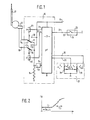
- FIG. 1 shows the circuit arrangement according to the invention for extending and retracting a motor antenna
- FIG. 2 shows the time course of the motor current when an end stop of the antenna is reached.
- FIG. 1 shows the circuit arrangement for extending and retracting a motor-driven antenna of a motor vehicle in a switching device 10. It is connected to the positive pole of the vehicle electrical system via a positive terminal 11.
- a collector motor 12 for driving the telescopic antenna 13 is connected to two output terminals 14 and 15 of the switching device 10. Terminals 14 and 15 are connected to two change-over switches for the purpose of reversing the direction of rotation of motor 12, namely according to the present exemplary embodiment with two relay contacts r1 and r2 two relays R1, R2 serving as change-over switches, which are each actuated by the associated windings of relays R1 and R2 .
- the normally closed contacts 16 and 17 are connected to ground via a measuring resistor 18, the normally open contacts 19 and 20 are connected to the positive terminal 11.
- the switching device 10 is also connected with an input terminal 21 to a control line 22, which is connected to positive potential when a car radio 23 is switched on via a switch-on contact 24 arranged there.
- the outputs of a two-pole toggle switch 27 are also connected via two further input terminals 25 and 26 of the switching device 10, with which the extension length of the antenna can be changed when the car radio 23 is switched on.
- the two pivotable switching contacts 28 and 29 of the toggle switch 27 are grounded.
- the toggle switch 27 has five switch positions, the function of which will be explained later. It is shown in Fig. 1 in a middle switching position.
- a control circuit which is implemented by a microprocessor 30, is provided for controlling the relays R1 and R2.
- the microprocessor 30 receives its supply voltage via the positive terminal 11 and a signal for extending or retracting the antenna 13 from the car radio 23 via the input terminal 21.
- the relays R1 and R2 are switched via the outputs 31 and 32 of the microprocessor 30.
- a signal input 34 of the microprocessor 30 is connected via a signal converter 33 to the measuring resistor 18 in the supply circuit of the motor 12 for the antenna drive.
- the toggle switch 27 is connected to the microprocessor 30 on the input side via the input terminals 25 and 26.
- the microprocessor 30 When the radio 23 is switched on, the microprocessor 30 now outputs a control voltage at its output 31, which excites the relay R1. As a result, the associated relay contact r1 is switched over and connected to the normally open contact 20, so that a motor current i from the positive terminal 11 via the relay contact r1 to the motor 12 and from there via the relay contact r2, the normally closed contact 16 of the relay R2 and via the measuring resistor 18 Mass flows. A voltage drop proportional to the motor current occurs at the measuring resistor 18 and is supplied to the signal converter 33. Since the motor current in the motor 12 flows by brushing over a revolving collector, a ripple occurs in the motor current i, which ripple occurs on the brushes of the motor 12 when it passes through the collector fins.
- the period of this ripple is inversely proportional or the frequency is proportional to the speed of the motor 12.
- the ripple of the motor current i is now detected in the signal converter 33 connected to the measuring resistor 18, and corresponding digital pulses are given to the input of the microprocessor 30.
- the digital pulses at the output of the signal converter 33 have the same frequency as the ripple of the motor current i.
- the microprocessor 30 determines the period of the ripple of the motor current. It is indicated in Fig. 2 for extending or retracting the antenna 13 with T1.
- the motor speed goes to zero, the motor current increases and the ripple of the motor current i decreases in frequency.
- the period indicated with T2 increases accordingly when the stop is reached.
- the frequency drop in the ripple or the extension of the period of the ripple is detected by the microprocessor 30 via the signal converter 33.
- the microprocessor 30 switches off the relay R1 and thus the motor 12 via the output 31.
- the motor 12 is stopped immediately by short-circuit braking, in that the motor circuit r1 and r2 is short-circuited as shown in FIG. 1.
- the microprocessor 30 maintains a pause time of 0.5 s, so that the motor 12 comes to a standstill beforehand.
- the microprocessor 30 also counts the digital pulses occurring at its signal input 34, which are generated with the frequency of the ripple of the motor current i in the signal converter 33. By comparing the number of to When the antenna telescope at signals input 34 comes to a standstill with a predetermined value, the microprocessor 30 recognizes whether the antenna 13 ran against its end stop when it was extended or retracted, or whether it encountered an obstacle beforehand. Should this e.g. B. due to contamination or icing, the motor 12 is also switched off by the microprocessor 30 due to the longer period of the ripple of the motor current i.
- the motor 12 is switched on again twice by the microprocessor 30 by means of a corresponding program, so that the motor 12 starts with full torque and tries to overcome the obstacle. If this does not succeed the second time, the motor 12 is finally switched off by the microprocessor 30. The corresponding process is repeated in the same way when the radio 23 is switched off. In this case, the plus potential is switched off from the input terminal 21 and the microprocessor 30 then switches on the relay R2 via the output 32 to retract the antenna 13.
- the toggle switch 27 is intended to make it possible to adapt the extension length of the antenna to the local reception conditions.
- the antenna is completely extended or retracted when the radio 33 is switched on and off when the toggle switch 28 is pivoted to the left into the first switching position a.
- it In its central position shown in FIG. 1, it assumes a second switching position c, in which only the input terminal 26 of the switching device 10 is connected to ground via the switching contact 28 of the toggle switch 27. Since the input terminal 25 is not grounded, this second switch position of the toggle switch 27 can be detected by the microprocessor 30.
- the antenna 13 is now guided over the microprocessor 30 into a half-extended position when the radio 23 is switched on, by first switching on the relay R1 via the output 31 of the microprocessor 30 and then via the signal input 34 the number of Revolutions of the motor 12 is counted by counting the pulses of the motor current i.
- the relay R1 is switched off via the output 31 and the motor 12 is thus switched off.
- the microprocessor 30 is programmed in such a way that the number of pulses required for switching off is reached at the signal input 34 when the antenna 13 is half extended.
- toggle switch 27 was previously in its first switch position a, and is only moved into its second switch position c according to FIG. 1 after the radio 23 has been switched on, then the antenna 13 'is retracted in half by a corresponding program of the microprocessor 30.
- the toggle switch 27 is pivoted fully to the right into a third switch position e, so that the input terminals 25 and 26 via the switch contacts 28 and 29 of the toggle switch 27 open Mass are laid. This switching position is therefore detected by the microprocessor 30 via the input terminals 25 and 26. A corresponding program ensures that the antenna 13 is not extended when the radio 23 is switched on.
- the toggle switch 27 is pivoted to the right in the third switch position e when the radio 23 is switched on, the microprocessor 30 switches on the relay R2 via the output 32, so that the antenna 13 is retracted.
- the toggle switch 27 is also provided with two key positions b and d, which are each between two switch positions.
- the antenna 13 can be retracted or extended step by step via these key positions.
- the toggle switch must first be set to the second switch position c according to FIG. 1.
- antenna 13 extends halfway. If the toggle switch 27 is now briefly moved to the left into the first pushbutton position b, the ground connection of the input terminal 26 is thus interrupted via the switch contact 28 of the toggle switch 27.
- the microprocessor 30 switches on the relay R1 via the output 31 and the antenna 13 is extended further.
- the path of the antenna 13 which has now been covered is in turn detected by the microprocessor 30 at the signal input 34.
- the microprocessor 30 switches the relay R1 off again after a path of approximately 10 cm exit length of the antenna 13 specified by the microprocessor 30, provided that the toggle switch 27 is pivoted back into the central position c. If, however, the toggle switch 27 is held in this key position, the antenna 13 extends completely. If, on the other hand, the antenna is to be retracted further, the toggle switch 27 is briefly pivoted to the right into the second key position d. As a result, the input terminal 25 is now also briefly grounded via the switch contact 29, which is detected by the microprocessor 30. The latter now switches on the relay R2 via the output 32 and the antenna is moved in a certain way in a corresponding manner and then the microprocessor 30 switches off the motor 12. If, however, the toggle switch 27 is held in this second key position, the antenna 13 retracts completely.
- the control circuit 30 implemented by the microprocessor is designed to be capable of learning by first switching on the drive motor 30 in a first time period of, for example, 1 s via the measuring resistor and the signal former 33 the mean ripple of the motor current i is determined. The determined value is now saved and compared with the value just measured. When the continuously measured period is exceeded by a predetermined percentage of the stored value, the motor 12 is then switched off via the relays R1, R2. This makes it possible to eliminate frequency deviations in the ripple of the motor current i, which are caused by different motor types, drives, different environmental conditions, by aging and contamination of the drive, and by production variations in the overall drive.
- the microprocessor 30 is programmed so that the motor 12 is only switched off by 50% when the previously determined average period is exceeded.
- the invention is not limited to the exemplary embodiment shown, since instead of a motor-driven antenna, other reciprocating devices of the motor vehicle, such as, for example, sunroofs and window panes, can be controlled in the same way.
- a current transformer can be used instead of a low-resistance measuring resistor 18.
- semiconductors dimensioned for corresponding switching powers can be used instead of relays R1 and R2.
- the toggle switch 27 it is possible to use a potentiometer or a switch with a potentiometer, the position of which is queried by the control circuit 30 and specifies the extension length of the antenna 13 or another drive for the control circuit.
- the circuit arrangement 30 can be expanded in such a way that it displays the determined position of the antenna or the extension length via a light-emitting diode chain.
- the control circuit emits a display signal when such unusual operating conditions are detected and, if necessary, at the same time permanently switches off the drive for a longer time.
Landscapes
- Engineering & Computer Science (AREA)
- Power Engineering (AREA)
- Details Of Aerials (AREA)
- Stopping Of Electric Motors (AREA)
- Fittings On The Vehicle Exterior For Carrying Loads, And Devices For Holding Or Mounting Articles (AREA)
- Control Of Electric Motors In General (AREA)
- Control Of Direct Current Motors (AREA)
Applications Claiming Priority (2)
| Application Number | Priority Date | Filing Date | Title |
|---|---|---|---|
| DE19823226614 DE3226614A1 (de) | 1982-07-16 | 1982-07-16 | Schaltungsanordnung zum ein- und ausfahren einer motorgetriebenen antenne |
| DE3226614 | 1982-07-16 |
Publications (2)
| Publication Number | Publication Date |
|---|---|
| EP0100852A1 EP0100852A1 (de) | 1984-02-22 |
| EP0100852B1 true EP0100852B1 (de) | 1986-02-19 |
Family
ID=6168570
Family Applications (1)
| Application Number | Title | Priority Date | Filing Date |
|---|---|---|---|
| EP19830106320 Expired EP0100852B1 (de) | 1982-07-16 | 1983-06-29 | Schaltungsanordnung zum Ein- und Ausfahren einer motorgetriebenen Antenne |
Country Status (5)
| Country | Link |
|---|---|
| US (1) | US4514670A (2) |
| EP (1) | EP0100852B1 (2) |
| JP (1) | JPS5932379A (2) |
| DE (2) | DE3226614A1 (2) |
| ES (1) | ES524165A0 (2) |
Cited By (1)
| Publication number | Priority date | Publication date | Assignee | Title |
|---|---|---|---|---|
| DE102011081841A1 (de) | 2011-08-31 | 2013-02-28 | Robert Bosch Gmbh | Antriebseinheit |
Families Citing this family (77)
| Publication number | Priority date | Publication date | Assignee | Title |
|---|---|---|---|---|
| JPS5986707U (ja) * | 1982-12-03 | 1984-06-12 | ナイルス部品株式会社 | 車両用オ−トアンテナ制御装置 |
| US4558259A (en) * | 1984-01-09 | 1985-12-10 | General Motors Corporation | Controller for a movable motor vehicle headlamp mechanism |
| JPH0620161B2 (ja) * | 1984-10-23 | 1994-03-16 | 日本電装株式会社 | 車両用電動アンテナ装置 |
| US4701684A (en) * | 1984-11-26 | 1987-10-20 | Automatic Roller Doors Australia Pty. Ltd. | Door or gate obstruction control |
| JPH0547255Y2 (2) * | 1985-09-04 | 1993-12-13 | ||
| US4672278A (en) * | 1985-10-09 | 1987-06-09 | Nartron Corporation | Antenna relay method and apparatus |
| WO1987004567A1 (en) * | 1986-01-16 | 1987-07-30 | Nippon Antenna Co., Ltd. | Mechanism for controlling electrically driven antenna |
| JPS62178192A (ja) * | 1986-01-31 | 1987-08-05 | Diesel Kiki Co Ltd | モ−タ制御装置 |
| JPS62264703A (ja) * | 1986-04-22 | 1987-11-17 | Harada Kogyo Kk | 車両用モ−タアンテナの制御装置 |
| GB2198860B (en) * | 1986-10-03 | 1990-12-12 | Jidosha Denki Kogyo Kk | An automatic opening and closing device for a window |
| US4733101A (en) * | 1986-11-17 | 1988-03-22 | General Motors Corporation | Vehicle power antenna control with inhibit during cranking |
| US4730152A (en) * | 1986-11-17 | 1988-03-08 | General Motors Corporation | Vehicle power antenna control with drive stress limiting |
| JP2725247B2 (ja) * | 1986-12-15 | 1998-03-11 | キヤノン株式会社 | モータ駆動制御装置 |
| IT1204907B (it) * | 1987-01-15 | 1989-03-10 | Cavis Cavetti Isolati Spa | Circuito per il controllo della rotazione di motori,utilizzati per la moviemntazione di vetri elettrici e per una molteplicita' di applicazioni su autoveicoli e simili |
| US4857813A (en) * | 1987-03-17 | 1989-08-15 | Jidosha Denki Kogyo Kabushiki Kaisha | Self-stopping motor control circuit |
| JPH01151304A (ja) * | 1987-12-08 | 1989-06-14 | Harada Ind Co Ltd | 自動車用モータアンテナ制御装置 |
| JPH0748609B2 (ja) * | 1988-01-11 | 1995-05-24 | 原田工業株式会社 | 自動車用ロッドアンテナ制御装置 |
| US4884013A (en) * | 1988-01-15 | 1989-11-28 | Sherwood Medical Company | Motor unit for a fluid pump and method of operation |
| US4947051A (en) * | 1988-01-22 | 1990-08-07 | Mitsubishi Denki Kabushiki Kaisha | Starter protector for an engine |
| US4972129A (en) * | 1988-07-18 | 1990-11-20 | Nippon Seiko Kabushiki Kaisha | Passive seat belt apparatus |
| DE3833702A1 (de) * | 1988-10-04 | 1990-04-05 | Ako Werke Gmbh & Co | Steuerschaltung eines universalmotors |
| US4990929A (en) * | 1988-12-15 | 1991-02-05 | Harada Kogyo Kabushiki Kaisha | Motor-driven automobile antenna with timer circuit |
| SE500651C2 (sv) * | 1989-01-20 | 1994-08-01 | Ambient Energy Design | Anordning för reglering av drivmotorn hos fönsterjalusier eller markiser |
| GB8921025D0 (en) * | 1989-09-16 | 1989-11-01 | Britax Weathershields | Motor position sensor |
| US5235344A (en) * | 1990-03-16 | 1993-08-10 | Harada Industry Co., Ltd. | Drive control apparatus for an electrically-driven type extensible/retractable antenna |
| JP2533217B2 (ja) * | 1990-03-16 | 1996-09-11 | 原田工業株式会社 | 電動伸縮形アンテナ駆動制御装置 |
| US5132602A (en) * | 1990-10-02 | 1992-07-21 | Calsonic International, Inc. | Actuator positioning apparatus |
| JPH0793998B2 (ja) * | 1990-11-28 | 1995-10-11 | ブラザー工業株式会社 | ミシンモータの回転制御装置 |
| US5198734A (en) * | 1992-03-09 | 1993-03-30 | Marathon Oil Company | Method and means for stopping backspinning motor |
| US7548037B2 (en) | 1992-04-22 | 2009-06-16 | Nartron Corporation | Collision monitoring system |
| US6404158B1 (en) | 1992-04-22 | 2002-06-11 | Nartron Corporation | Collision monitoring system |
| US7579802B2 (en) * | 1992-04-22 | 2009-08-25 | Nartron Corporation | Collision monitoring system |
| US6064165A (en) * | 1992-04-22 | 2000-05-16 | Nartron Corporation | Power window or panel controller |
| US5952801A (en) * | 1992-04-22 | 1999-09-14 | Nartron Corporation | Power window or panel controller |
| JPH06125212A (ja) * | 1992-10-12 | 1994-05-06 | Harada Ind Co Ltd | 電動式伸縮形アンテナ駆動制御装置 |
| JPH0723577A (ja) * | 1993-01-27 | 1995-01-24 | Nec Corp | モータ制御回路 |
| ES2115960T3 (es) * | 1993-07-08 | 1998-07-01 | Doduco Gmbh | Procedimiento para el mando de un motor de corriente continua previsto para mover una luna de ventanilla en un vehiculo automovil. |
| US5449987A (en) * | 1993-09-24 | 1995-09-12 | Truth Division Of Spx Corporation | Window operator control |
| JPH07241096A (ja) * | 1994-02-28 | 1995-09-12 | Unisia Jecs Corp | 電動モータの制御装置 |
| US5585705A (en) * | 1994-05-05 | 1996-12-17 | Leopold Kostal Gmbh & Co. Kg | Process for monitoring movement of closure devices which may be adjusted by motors |
| DE4416878A1 (de) * | 1994-05-13 | 1995-11-16 | Bosch Gmbh Robert | Vorrichtung zum Steuern von motorisch betätigbaren Teilen eines Kraftfahrzeugs |
| JPH0878506A (ja) * | 1994-09-05 | 1996-03-22 | Canon Inc | 位置決め制御装置 |
| DE4432058A1 (de) * | 1994-09-09 | 1996-03-14 | Bosch Gmbh Robert | Schaltung zum Betreiben eines Elektromotors |
| US5610484A (en) * | 1995-05-04 | 1997-03-11 | Itt Automotive Electrical Systems, Inc. | Auto reverse power closure system |
| DE19527456B4 (de) * | 1995-07-27 | 2004-12-09 | Robert Bosch Gmbh | Verfahren zum Positionieren eines Teils |
| DE19531456C2 (de) * | 1995-08-26 | 2002-06-06 | Siemens Ag | Verfahren zur Feststellung des Einklemmfalles bei einem elektromotorisch angetriebenen Fensterheber und Vorrichtung zur Durchführung des Verfahrens |
| DE59610883D1 (de) * | 1995-10-28 | 2004-02-05 | Elero Gmbh | Verfahren zum Antreiben von elektromotorisch betriebenen Markisen oder dergleichen |
| FR2767981B1 (fr) * | 1997-09-02 | 1999-11-26 | Valeo Electronique | Dispositif pour le suivi de la rotation d'un moteur a courant continu |
| KR100288128B1 (ko) * | 1997-09-30 | 2001-05-02 | 윤종용 | 무선통신기기의 안테나 자동 인출/인입 장치 및 방법 |
| FR2783983B1 (fr) * | 1998-09-30 | 2000-12-22 | Valeo Electronique | Perfectionnement aux dispositifs pour le suivi de la rotation d'un moteur a courant continu |
| JP4244412B2 (ja) * | 1998-09-30 | 2009-03-25 | アイシン精機株式会社 | 直流モータのモータ回転パルス生成回路およびその回路を用いた挟み込み検知装置 |
| FR2790885B1 (fr) * | 1999-03-11 | 2001-07-13 | Valeo Electronique | Dispositifs pour le suivi de la rotation d'un moteur a courant continu |
| FR2792463B1 (fr) * | 1999-04-19 | 2004-03-12 | Peugeot Citroen Automobiles Sa | Antenne de vehicule automobile |
| DE10028040B4 (de) * | 2000-06-06 | 2012-01-19 | Leopold Kostal Gmbh & Co. Kg | Verfahren zum Einfahren eines durch einen Elektromotor zwischen zwei jeweils als Endanschlag ausgebildeten Blockpositionen angetriebenen Elements in eine Blockposition |
| BR0106746A (pt) * | 2000-06-06 | 2002-04-02 | Kostal Leopold Gmbh & Co Kg | Processo e dispositivo para determinar a posição de giro do eixo de acionamento de um motor de corrente contìnua |
| CN1152463C (zh) * | 2000-06-09 | 2004-06-02 | 株式会社理光 | 直流马达 |
| US7030509B2 (en) * | 2001-08-09 | 2006-04-18 | Asmo Co., Ltd. | Apparatus and method for controlling movement of a movable member |
| DE10222539A1 (de) * | 2002-05-17 | 2003-11-27 | Siemens Ag | Verfahren zum Betreiben eines Stellantriebs |
| US6794837B1 (en) * | 2002-05-31 | 2004-09-21 | Valeo Electrical Systems, Inc. | Motor speed-based anti-pinch control apparatus and method with start-up transient detection and compensation |
| US7084597B2 (en) * | 2002-06-03 | 2006-08-01 | Denso Corporation | Motor control apparatus |
| FR2899923B1 (fr) * | 2006-04-14 | 2009-02-06 | Somfy Sas | Procede de commande et installation de store commandee par ce procede |
| DE10242334B4 (de) | 2002-09-12 | 2011-12-22 | Robert Bosch Gmbh | Verfahren und Einrichtung zur Drehzahlmessung eines getaktet angesteuerten elektrischen Motors |
| US6960895B2 (en) * | 2003-03-20 | 2005-11-01 | Siemens Vdo Automotive Inc. | Coupled RFI choke as stall detection means for brush type DC motor |
| US6844692B1 (en) * | 2003-08-22 | 2005-01-18 | Hella Electronics Corp. | Climate control system and motor actuator therefor |
| DE10351232B4 (de) * | 2003-11-03 | 2011-09-29 | Continental Automotive Gmbh | Verfahren zur Blockerkennung bei einem von einem Elektromotor angetriebenen System |
| JP4127251B2 (ja) * | 2004-07-23 | 2008-07-30 | 株式会社デンソー | 直流モータの回転情報検出装置 |
| EP1679777A1 (de) * | 2005-01-05 | 2006-07-12 | Behr-Hella Thermocontrol GmbH | Vorrichtung zur Defekterkennung bei einem Kollektor-Gleichstrommotor basierend auf der Welligkeit des Ankerstroms |
| US7180255B2 (en) * | 2005-01-26 | 2007-02-20 | Delphi Technologies, Inc. | Controlling the release of a brush motor which has applied a load |
| US20060261763A1 (en) * | 2005-05-23 | 2006-11-23 | Masco Corporation | Brushed motor position control based upon back current detection |
| ATE496421T1 (de) * | 2005-09-05 | 2011-02-15 | Ideassociates Iom Ltd | Verfahren zum steuern eines mechanisch kommutierten elektromotors |
| JP2008087754A (ja) * | 2006-09-04 | 2008-04-17 | Ichikoh Ind Ltd | 車両用ミラー装置 |
| JP4850042B2 (ja) * | 2006-11-29 | 2012-01-11 | 株式会社今仙電機製作所 | モータ駆動装置 |
| WO2008071538A1 (de) * | 2006-12-14 | 2008-06-19 | Continental Automotive Gmbh | Verfahren und vorrichtung zum verfolgen der position einer von einem elektromotor angetriebenen komponente |
| US20080298784A1 (en) * | 2007-06-04 | 2008-12-04 | Mark Allen Kastner | Method of Sensing Speed of Electric Motors and Generators |
| US9989961B2 (en) | 2014-12-03 | 2018-06-05 | Winegard Company | Antenna positioning system |
| FR3079177B1 (fr) * | 2018-03-22 | 2020-11-06 | Aml Systems | Dispositif de correction d’eclairage a moteur electrique a courant continu pour vehicule automobile. |
| DE102020127361A1 (de) | 2020-10-16 | 2022-04-21 | Vega Grieshaber Kg | Sensor mit einer verlagerbaren Antenne und Verfahren zum Betreiben eines Sensors |
Citations (1)
| Publication number | Priority date | Publication date | Assignee | Title |
|---|---|---|---|---|
| WO1981003715A1 (fr) * | 1980-06-11 | 1981-12-24 | Faiveley Sa | Dispositif pour couper automatiquement l'alimentation electrique d'un moteur et son utilisation |
Family Cites Families (16)
| Publication number | Priority date | Publication date | Assignee | Title |
|---|---|---|---|---|
| US3199006A (en) * | 1963-01-23 | 1965-08-03 | Bendix Corp | Switching logic means for a discrete servomotor mechanism |
| GB1334228A (en) * | 1969-12-30 | 1973-10-17 | Lucas Industries Ltd | Window lift control systems |
| DE2141150A1 (de) * | 1971-08-17 | 1973-02-22 | Daimler Benz Ag | Vorrichtung zum schutz vor dem einklemmen bei elektromotorisch in einem festen oeffnungsrahmen bewegbaren fensterscheiben od. dgl. bauteilen, insbesondere von kraftfahrzeugen |
| US3881140A (en) * | 1974-03-01 | 1975-04-29 | American Seating Co | System for expanding and retracting telescoping seating row sections |
| DE2428674A1 (de) * | 1974-06-14 | 1976-01-02 | Hirschmann Radiotechnik | Elektronische anordnung zum einstellen des abschaltzeitpunktes von kraftfahrzeug - motorantennen |
| JPS5267714A (en) * | 1975-12-03 | 1977-06-04 | Fujitsu Ltd | Motor start control system |
| DE2640995A1 (de) * | 1976-09-11 | 1978-03-16 | Daimler Benz Ag | Aus- und einfahrbare antenne fuer rundfunkempfaenger |
| US4263536A (en) * | 1978-08-07 | 1981-04-21 | Clopay Corporation | Control circuit for a motor-driven door operator |
| DE2846993A1 (de) * | 1978-10-28 | 1980-04-30 | Bosch Gmbh Robert | Antriebseinrichtung fuer eine teleskopantenne |
| JPS55136884A (en) * | 1979-04-09 | 1980-10-25 | Sony Corp | Controlling circuit for motor |
| DE2922197A1 (de) * | 1979-05-31 | 1980-12-04 | Hirschmann Radiotechnik | Selbsttaetige ueberlast-abschalteinrichtung fuer gleichstrom-motorantriebe |
| DE2922160A1 (de) * | 1979-05-31 | 1980-12-04 | Rau Swf Autozubehoer | Wischanlage fuer kraftfahrzeuge |
| FR2465061A1 (fr) * | 1979-09-13 | 1981-03-20 | Renault | Leve-vitre electrique a commande impulsionnelle |
| DE3011387C2 (de) * | 1980-03-25 | 1984-05-03 | Robert Bosch Gmbh, 7000 Stuttgart | Schaltungsanordnung zum Ein- und Ausfahren einer von einem Elektromotor getriebenen Antenne |
| JPS5752390A (en) * | 1980-09-12 | 1982-03-27 | Toshiba Corp | Rotational pulse detecting circuit for reel motor |
| US4364003A (en) * | 1980-09-16 | 1982-12-14 | Mary A. Baldwin | Electronic gate control |
-
1982
- 1982-07-16 DE DE19823226614 patent/DE3226614A1/de not_active Withdrawn
-
1983
- 1983-06-29 EP EP19830106320 patent/EP0100852B1/de not_active Expired
- 1983-06-29 DE DE8383106320T patent/DE3362179D1/de not_active Expired
- 1983-07-06 US US06/511,152 patent/US4514670A/en not_active Expired - Lifetime
- 1983-07-11 JP JP58124871A patent/JPS5932379A/ja active Granted
- 1983-07-15 ES ES524165A patent/ES524165A0/es active Granted
Patent Citations (1)
| Publication number | Priority date | Publication date | Assignee | Title |
|---|---|---|---|---|
| WO1981003715A1 (fr) * | 1980-06-11 | 1981-12-24 | Faiveley Sa | Dispositif pour couper automatiquement l'alimentation electrique d'un moteur et son utilisation |
Cited By (1)
| Publication number | Priority date | Publication date | Assignee | Title |
|---|---|---|---|---|
| DE102011081841A1 (de) | 2011-08-31 | 2013-02-28 | Robert Bosch Gmbh | Antriebseinheit |
Also Published As
| Publication number | Publication date |
|---|---|
| DE3362179D1 (en) | 1986-03-27 |
| US4514670A (en) | 1985-04-30 |
| JPS5932379A (ja) | 1984-02-21 |
| ES8404572A1 (es) | 1984-04-16 |
| ES524165A0 (es) | 1984-04-16 |
| DE3226614A1 (de) | 1984-01-19 |
| JPH0440954B2 (2) | 1992-07-06 |
| EP0100852A1 (de) | 1984-02-22 |
Similar Documents
| Publication | Publication Date | Title |
|---|---|---|
| EP0100852B1 (de) | Schaltungsanordnung zum Ein- und Ausfahren einer motorgetriebenen Antenne | |
| EP0716214B1 (de) | Verfahren und Vorrichtung zur Stillstandssteuerung von elektromotorisch betriebenen Rolläden oder dergleichen | |
| DE2918658C3 (de) | Wischanlage für Fahrzeuge | |
| EP0148318B1 (de) | Sicherheitsschaltung für elektromotorisch angetriebene Fensterheber für Automobile und ähnliche Fahrzeuge | |
| DE2851727C2 (2) | ||
| DE3620104C2 (de) | Steuereinrichtung für einen Gleichstrom-Scheibenwischermotor | |
| EP0019695A1 (de) | Selbsttätige Überlast-Abschalteinrichtung für Gleichstrom-Motorantriebe | |
| DE19803709A1 (de) | Automatisches Öffnungs- und Schließsystem für eine Fahrzeugschiebetür | |
| DE10014073B4 (de) | Sicherheitsgerät für motorbetriebene Fenster | |
| EP0028386B1 (de) | Steueranordnung für eine Wischanlage für Kraftfahrzeugscheiben | |
| DE3305770A1 (de) | Schaltungsanordnung zum ein- und ausschalten eines elektromotorischen antriebes | |
| EP0852650B1 (de) | Getriebemotor-stellantrieb, insbesondere fensterheber- bzw. schiebedachantrieb für ein kraftfahrzeug | |
| EP0283005A1 (de) | Verfahren und Intervallschalter mit einer Schaltungsanordnung zur Steuerung des Wischintervalls von Scheibenwischern in Fahrzeugen | |
| EP0590227B1 (de) | Blockiererkennung für Gleichstrommotoren | |
| DE3335407C3 (de) | Sicherheitseinrichtung für einen elektromechanischen Öffnungs- und Schließmechanismus | |
| DE2824510C2 (de) | Vorrichtung zum Steuern der Bewegung eines angetriebenen Tores | |
| WO1995031360A1 (de) | Scheibenwischvorrichtung | |
| EP0936341B1 (de) | Vorrichtung zur Steuerung der Bewegung einer Verdunkelungsvorrichtung | |
| DE3428898C2 (2) | ||
| DE3871534T2 (de) | Schaltanordnung zur steuerung der elektrischen motoren fuer das heben und senken der scheiben in kraftfahrzeugen und aehnlichen. | |
| DE2724275C2 (de) | Blinkeinrichtung zur Fahrtrichtungsanzeige von Fahrzeugen | |
| DE1530992A1 (de) | Vorrichtung zum OEffnen und Schliessen von Tueren,Schiebedaechern od.dgl.,insbesondere von Kraftfahrzeugen | |
| DE2824674C2 (de) | Waschvorrichtung für Fahrzeuge, insbesondere Nutzfahrzeuge | |
| DE4241996C2 (de) | Bremssteuerschaltung für einen Scheibenwischerantrieb | |
| DE3011387C2 (de) | Schaltungsanordnung zum Ein- und Ausfahren einer von einem Elektromotor getriebenen Antenne |
Legal Events
| Date | Code | Title | Description |
|---|---|---|---|
| PUAI | Public reference made under article 153(3) epc to a published international application that has entered the european phase |
Free format text: ORIGINAL CODE: 0009012 |
|
| 17P | Request for examination filed |
Effective date: 19830629 |
|
| AK | Designated contracting states |
Designated state(s): DE FR IT SE |
|
| GRAA | (expected) grant |
Free format text: ORIGINAL CODE: 0009210 |
|
| AK | Designated contracting states |
Designated state(s): DE FR IT SE |
|
| ET | Fr: translation filed | ||
| REF | Corresponds to: |
Ref document number: 3362179 Country of ref document: DE Date of ref document: 19860327 |
|
| ITF | It: translation for a ep patent filed | ||
| PLBE | No opposition filed within time limit |
Free format text: ORIGINAL CODE: 0009261 |
|
| STAA | Information on the status of an ep patent application or granted ep patent |
Free format text: STATUS: NO OPPOSITION FILED WITHIN TIME LIMIT |
|
| 26N | No opposition filed | ||
| ITTA | It: last paid annual fee | ||
| EAL | Se: european patent in force in sweden |
Ref document number: 83106320.1 |
|
| PGFP | Annual fee paid to national office [announced via postgrant information from national office to epo] |
Ref country code: FR Payment date: 20020622 Year of fee payment: 20 |
|
| PGFP | Annual fee paid to national office [announced via postgrant information from national office to epo] |
Ref country code: SE Payment date: 20020626 Year of fee payment: 20 |
|
| PGFP | Annual fee paid to national office [announced via postgrant information from national office to epo] |
Ref country code: DE Payment date: 20020802 Year of fee payment: 20 |
|
| EUG | Se: european patent has lapsed |