EP0101057A2 - Démultiplexeur - Google Patents
Démultiplexeur Download PDFInfo
- Publication number
- EP0101057A2 EP0101057A2 EP83107870A EP83107870A EP0101057A2 EP 0101057 A2 EP0101057 A2 EP 0101057A2 EP 83107870 A EP83107870 A EP 83107870A EP 83107870 A EP83107870 A EP 83107870A EP 0101057 A2 EP0101057 A2 EP 0101057A2
- Authority
- EP
- European Patent Office
- Prior art keywords
- demultiplexer
- input
- data stream
- line elements
- chain circuit
- Prior art date
- Legal status (The legal status is an assumption and is not a legal conclusion. Google has not performed a legal analysis and makes no representation as to the accuracy of the status listed.)
- Withdrawn
Links
- 238000004904 shortening Methods 0.000 claims description 2
- 230000005540 biological transmission Effects 0.000 description 1
- 238000006243 chemical reaction Methods 0.000 description 1
- 238000001514 detection method Methods 0.000 description 1
- 238000011835 investigation Methods 0.000 description 1
- 239000013589 supplement Substances 0.000 description 1
- 238000011144 upstream manufacturing Methods 0.000 description 1
Images

Classifications
-
- H—ELECTRICITY
- H04—ELECTRIC COMMUNICATION TECHNIQUE
- H04J—MULTIPLEX COMMUNICATION
- H04J3/00—Time-division multiplex systems
- H04J3/02—Details
- H04J3/04—Distributors combined with modulators or demodulators
- H04J3/047—Distributors with transistors or integrated circuits
Definitions
- Demultiplexer for a bit-wise distribution of a serial binary data stream on n outputs.
- Demultiplexers of this type are known from the magazine "Telcom Report", 2 (1979), supplement digital transmission technology, pages 59 to 64 for a bit rate up to 139 Mbit / s.
- the serial-parallel conversion was previously carried out by means of shift registers in such a way that the data were written into the register one after the other and read out in parallel at times which are a whole multiple of the input clock.
- a practically used demultiplexer is described in DE-PS 28 56 565.
- the object of the invention is to provide a demultiplexer for high bit sequences with lower power dissipation.
- this object is achieved according to the invention in that a chain circuit of n-1 line elements of the signal propagation time of a bit length of the serial Data stream is provided that the input of the chain circuit is provided as a demultiplexer input and that n D flip-flops are provided, the input of which are connected either to the input of the chain circuit or to the output of one line element in each case and whose output serve as demultiplexer outputs.
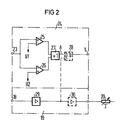
- the demultiplexer according to FIG. 1 has an input 1, a chain circuit 2 comprising line elements 3 to 5 and a terminating resistor 6, D flip-flops 10 to 13 and outputs 14 to 17.
- the clock supply contains a clock input 18, an amplifier 19, a phase shifter 20 and a frequency divider 21.
- a decision stage 24 with input 23 can be connected upstream of input 1.
- the decision stage 24 contains two threshold value detectors 25 and 26, an OR gate 27 and a D flip-flop 28 for high bit rates.
- the amplifier 19 contains an amplifier stage 29 and, when the D flip-flop 28 is used, a further amplifier stage 30.
- an AMI-coded (alternate mark inversion) data stream is applied to the input 23, it reaches the threshold value detectors 25 and 26 with the thresholds U1 and U2.
- the threshold detector 25 is at Exceeding the threshold U1 and the threshold value detector 26 when the threshold U2 is exceeded a logic "1".
- the OR gate 27 then outputs a binary data stream via the input 1 to the chain circuit 2.
- the individual line elements 3 to 5 have a signal propagation time which corresponds to a bit length of the serial data stream at the input 1. With a bit sequence of 565 Mbit / s, the line elements in the form of cables are approximately 40 cm long. Strip lines on a carrier with a high shortening factor can have a considerably shorter length.
- the clock of the serial data stream at input 1 is applied to input 18. This is amplified in the amplifier 29 and, if necessary, corrected in phase in the phase shifter 20 before it is fed to the frequency divider 21.
- the clock T at input 1 is divided by four. With this clock T / 4 at the connection 22, the four D flip-flops 10 to 13 take over the signals at the external connections 1 and 9 and at the taps 7 and 8 of the derailleur circuit 2 and pass them on to the outputs 14 to 17.
Landscapes
- Engineering & Computer Science (AREA)
- Microelectronics & Electronic Packaging (AREA)
- Computer Networks & Wireless Communication (AREA)
- Signal Processing (AREA)
- Dc Digital Transmission (AREA)
- Time-Division Multiplex Systems (AREA)
- Medicines Containing Material From Animals Or Micro-Organisms (AREA)
- Control Of Motors That Do Not Use Commutators (AREA)
Applications Claiming Priority (2)
| Application Number | Priority Date | Filing Date | Title |
|---|---|---|---|
| DE19823230054 DE3230054A1 (de) | 1982-08-12 | 1982-08-12 | Demultiplexer |
| DE3230054 | 1982-08-12 |
Publications (2)
| Publication Number | Publication Date |
|---|---|
| EP0101057A2 true EP0101057A2 (fr) | 1984-02-22 |
| EP0101057A3 EP0101057A3 (fr) | 1985-05-15 |
Family
ID=6170721
Family Applications (1)
| Application Number | Title | Priority Date | Filing Date |
|---|---|---|---|
| EP83107870A Withdrawn EP0101057A3 (fr) | 1982-08-12 | 1983-08-09 | Démultiplexeur |
Country Status (6)
| Country | Link |
|---|---|
| EP (1) | EP0101057A3 (fr) |
| JP (1) | JPS5952914A (fr) |
| AU (1) | AU542432B2 (fr) |
| BR (1) | BR8304316A (fr) |
| DE (1) | DE3230054A1 (fr) |
| NO (1) | NO832699L (fr) |
Cited By (3)
| Publication number | Priority date | Publication date | Assignee | Title |
|---|---|---|---|---|
| EP0180988A3 (en) * | 1984-11-08 | 1988-10-05 | Canon Kabushiki Kaisha | System for controlling image formation system for controlling image formation |
| EP0200569A3 (fr) * | 1985-05-03 | 1988-10-05 | Advanced Micro Devices, Inc. | Dispositif à circuit monolithique intégré |
| EP0453129A1 (fr) * | 1990-04-10 | 1991-10-23 | AT&T Corp. | Système de commutation temporel à grande vitesse |
Families Citing this family (3)
| Publication number | Priority date | Publication date | Assignee | Title |
|---|---|---|---|---|
| US4866711A (en) * | 1986-03-04 | 1989-09-12 | Christian Rovsing A/S Af 1984 | Method of multiplex/demultiplex processing of information and equipment for performing the method |
| DE3782894T2 (de) * | 1986-03-04 | 1993-04-08 | Bolt Beranek & Newman | Verfahren zur behandlung von daten multiplex/demultiplex sowie vorichtung zur durchfuehrung. |
| JPH0432824Y2 (fr) * | 1986-04-23 | 1992-08-06 |
Family Cites Families (6)
| Publication number | Priority date | Publication date | Assignee | Title |
|---|---|---|---|---|
| FR2265240B1 (fr) * | 1974-03-22 | 1977-09-30 | Constr Telephoniques | |
| DE2602937B1 (de) * | 1976-01-27 | 1977-05-05 | Siemens Ag | Demultiplexer fuer wortweise verschachtelte, urspruenglich synchrone digitalsignale |
| DE2714242C3 (de) * | 1977-03-30 | 1980-03-13 | Siemens Ag, 1000 Berlin Und 8000 Muenchen | Generator für binäre Quasizufallsfolgen |
| DE2814000C3 (de) * | 1978-03-31 | 1988-02-11 | Siemens AG, 1000 Berlin und 8000 München | Demultiplex-Anordnung |
| DE2856565B1 (de) * | 1978-12-28 | 1980-05-14 | Siemens Ag | Demultiplex-Anordnung |
| DE3037872C2 (de) * | 1980-10-07 | 1986-09-25 | Siemens AG, 1000 Berlin und 8000 München | Verfahren und Schaltungsanordnung zur seriellen Übertragung eines Taktsignals und mehrerer parallel ankommender binärer Datensignale |
-
1982
- 1982-08-12 DE DE19823230054 patent/DE3230054A1/de not_active Withdrawn
-
1983
- 1983-07-25 NO NO832699A patent/NO832699L/no unknown
- 1983-08-03 JP JP58141261A patent/JPS5952914A/ja active Pending
- 1983-08-09 EP EP83107870A patent/EP0101057A3/fr not_active Withdrawn
- 1983-08-11 AU AU17888/83A patent/AU542432B2/en not_active Expired - Fee Related
- 1983-08-11 BR BR8304316A patent/BR8304316A/pt unknown
Non-Patent Citations (2)
| Title |
|---|
| GRIVET, P.: "PHYSIQUE DES LIGNES DE HAUTE FREQUENCE ET D'ULTRA-HAUTE FREQUENCE". Tome 1. Parametres primaire et secondaires ondes progressives. Impulsions. 1969. MASSON ET Cie. PARIS (FR). Seiten 324 bis 348 * |
| IEEE 1974 INTERNATIONAL CONFERENCE ON COMMUNICATIONS. 17-19 June 1974 MINNEAPOLIS, MINNESOTA, NEW YORK (US). SEITEN 39D-1 bis 39D-5. G. HANKE: "PCM Receiving Equipment of a 640 MBITS/S waveguide transmission system using integrated circuits". * |
Cited By (5)
| Publication number | Priority date | Publication date | Assignee | Title |
|---|---|---|---|---|
| EP0180988A3 (en) * | 1984-11-08 | 1988-10-05 | Canon Kabushiki Kaisha | System for controlling image formation system for controlling image formation |
| US4980814A (en) * | 1984-11-08 | 1990-12-25 | Canon Kabushiki Kaisha | System for controlling image formation |
| EP0200569A3 (fr) * | 1985-05-03 | 1988-10-05 | Advanced Micro Devices, Inc. | Dispositif à circuit monolithique intégré |
| EP0453129A1 (fr) * | 1990-04-10 | 1991-10-23 | AT&T Corp. | Système de commutation temporel à grande vitesse |
| US5119368A (en) * | 1990-04-10 | 1992-06-02 | At&T Bell Laboratories | High-speed time-division switching system |
Also Published As
| Publication number | Publication date |
|---|---|
| NO832699L (no) | 1984-02-13 |
| BR8304316A (pt) | 1984-03-20 |
| EP0101057A3 (fr) | 1985-05-15 |
| AU542432B2 (en) | 1985-02-21 |
| DE3230054A1 (de) | 1984-02-16 |
| JPS5952914A (ja) | 1984-03-27 |
| AU1788883A (en) | 1984-02-16 |
Similar Documents
| Publication | Publication Date | Title |
|---|---|---|
| DE69332804T2 (de) | Verfahren und vorrichtung zur nrz-datensignalenübertragung durch eine isolierungbarriere in einer schnittstelle zwischen nachbarvorrichtungen auf einem bus | |
| DE69734182T2 (de) | Datenübertragungsverfahren, elektronisches Gerät und integrierte Bitübertragungsschichtsteuerschaltung | |
| DE10257867A1 (de) | Schnelle Schnittstelle für eine programmierbare Verbindungsschaltung | |
| DE3204900A1 (de) | Koppelanordnung | |
| DE69006806T2 (de) | Schleifenschlussanordnung für optisches Zeitgetrenntlage-Übertragungssystem. | |
| EP0115327B1 (fr) | Décodeur CMI | |
| DE3442613C2 (fr) | ||
| EP0101057A2 (fr) | Démultiplexeur | |
| DE4236488A1 (de) | Empfangsseitige Schaltung für ein System zur optischen Übertragung eines Digitalsignals über einen dispersionsbehafteten Lichtwellenleiter | |
| DE3878308T2 (de) | Uebertragungseinrichtung und sternschaltung zur verwendung in einer solchen uebertragungseinrichtung und einrichtung mit einer solchen schaltung. | |
| EP0103163B1 (fr) | Dispositif pour le démultiplexage synchrone d'un signal multiplex à division de temps | |
| EP0111309A2 (fr) | Décodeur CMI | |
| EP1062773A1 (fr) | Bus de donnees pour plusieurs noeuds | |
| DE68920703T2 (de) | Zuverlässige Datenrückgewinnung in einem Kodierer/Dekodierer. | |
| EP0101056A2 (fr) | Dispositif de synchronisation | |
| DE19627216A1 (de) | Vorrichtung zur Färbung optischer Signale | |
| EP0419895B1 (fr) | Méthode d'alimentation d'horloge pour les systèmes multiplexes | |
| EP0274647A1 (fr) | Procédé et dispositif de transmission d'un signal numérique de faible débit dans un créneau temporel d'un signal multiplexé dans le temps prévu pour un plus haut débit | |
| DE3403639A1 (de) | Selbstsynchronisierender entwuerfler | |
| DE3436722C2 (fr) | ||
| EP0044555B1 (fr) | Régénérateur comportant un vérificateur de violation de la règle du code | |
| DE19541065A1 (de) | Taktableitschaltung | |
| EP0028405B1 (fr) | Procédé et dispositif pour la réduction de la gigue lors du transcodage par blocs de signaux numériques | |
| DE3248624C2 (fr) | ||
| DE3235741A1 (de) | Digital-analog-wandler mit potentialtrennung |
Legal Events
| Date | Code | Title | Description |
|---|---|---|---|
| PUAI | Public reference made under article 153(3) epc to a published international application that has entered the european phase |
Free format text: ORIGINAL CODE: 0009012 |
|
| AK | Designated contracting states |
Designated state(s): AT CH DE FR IT LI |
|
| PUAL | Search report despatched |
Free format text: ORIGINAL CODE: 0009013 |
|
| AK | Designated contracting states |
Designated state(s): AT CH DE FR IT LI |
|
| STAA | Information on the status of an ep patent application or granted ep patent |
Free format text: STATUS: THE APPLICATION IS DEEMED TO BE WITHDRAWN |
|
| 18D | Application deemed to be withdrawn |
Effective date: 19860116 |
|
| RIN1 | Information on inventor provided before grant (corrected) |
Inventor name: MAGERL, JOHANN, ING.-GRAD. |