EP0101757A1 - Dispositif pour le marquage d'un point de terrain arpenté dans le sol - Google Patents
Dispositif pour le marquage d'un point de terrain arpenté dans le sol Download PDFInfo
- Publication number
- EP0101757A1 EP0101757A1 EP82108017A EP82108017A EP0101757A1 EP 0101757 A1 EP0101757 A1 EP 0101757A1 EP 82108017 A EP82108017 A EP 82108017A EP 82108017 A EP82108017 A EP 82108017A EP 0101757 A1 EP0101757 A1 EP 0101757A1
- Authority
- EP
- European Patent Office
- Prior art keywords
- ground
- permanent magnet
- permanent magnets
- plastic rod
- collar
- Prior art date
- Legal status (The legal status is an assumption and is not a legal conclusion. Google has not performed a legal analysis and makes no representation as to the accuracy of the status listed.)
- Ceased
Links
- 230000005291 magnetic effect Effects 0.000 claims description 9
- 239000000853 adhesive Substances 0.000 claims description 2
- 230000001070 adhesive effect Effects 0.000 claims description 2
- 230000007797 corrosion Effects 0.000 claims description 2
- 238000005260 corrosion Methods 0.000 claims description 2
- 239000002689 soil Substances 0.000 description 5
- 238000010276 construction Methods 0.000 description 4
- 239000003302 ferromagnetic material Substances 0.000 description 4
- XLYOFNOQVPJJNP-UHFFFAOYSA-N water Substances O XLYOFNOQVPJJNP-UHFFFAOYSA-N 0.000 description 3
- 238000005516 engineering process Methods 0.000 description 2
- 239000002184 metal Substances 0.000 description 2
- 229910052751 metal Inorganic materials 0.000 description 2
- VNWKTOKETHGBQD-UHFFFAOYSA-N methane Chemical compound C VNWKTOKETHGBQD-UHFFFAOYSA-N 0.000 description 2
- 101100334009 Caenorhabditis elegans rib-2 gene Proteins 0.000 description 1
- XEEYBQQBJWHFJM-UHFFFAOYSA-N Iron Chemical group [Fe] XEEYBQQBJWHFJM-UHFFFAOYSA-N 0.000 description 1
- 238000004873 anchoring Methods 0.000 description 1
- 238000009412 basement excavation Methods 0.000 description 1
- 238000009933 burial Methods 0.000 description 1
- 238000001514 detection method Methods 0.000 description 1
- 238000010438 heat treatment Methods 0.000 description 1
- 239000003550 marker Substances 0.000 description 1
- 238000005259 measurement Methods 0.000 description 1
- 239000010814 metallic waste Substances 0.000 description 1
- 239000003345 natural gas Substances 0.000 description 1
- 239000000126 substance Substances 0.000 description 1
Images

Classifications
-
- G—PHYSICS
- G01—MEASURING; TESTING
- G01C—MEASURING DISTANCES, LEVELS OR BEARINGS; SURVEYING; NAVIGATION; GYROSCOPIC INSTRUMENTS; PHOTOGRAMMETRY OR VIDEOGRAMMETRY
- G01C15/00—Surveying instruments or accessories not provided for in groups G01C1/00 - G01C13/00
- G01C15/02—Means for marking measuring points
- G01C15/04—Permanent marks; Boundary markers
-
- E—FIXED CONSTRUCTIONS
- E04—BUILDING
- E04H—BUILDINGS OR LIKE STRUCTURES FOR PARTICULAR PURPOSES; SWIMMING OR SPLASH BATHS OR POOLS; MASTS; FENCING; TENTS OR CANOPIES, IN GENERAL
- E04H12/00—Towers; Masts or poles; Chimney stacks; Water-towers; Methods of erecting such structures
- E04H12/22—Sockets or holders for poles or posts
- E04H12/2207—Sockets or holders for poles or posts not used
- E04H12/2215—Sockets or holders for poles or posts not used driven into the ground
Definitions
- the invention relates to a device for marking a measured terrain point in the ground.
- Such terrain points are, for example, the boundaries, in particular the corners of land, such as building plots, meadows, fields, forest land, but also roads, squares, etc. It is common to mark these measured terrain points, for example, boundary stones or markers or metal bars with a head in it Digging in or digging in soil.
- These markings which are usually located close to the surface of the earth, can easily be deliberately or also unintentionally moved or removed, for example when working on agricultural areas or during construction work, when filling with earth or the like.
- the markings can also be shifted, for example on river banks, in that the water pressure of the river exerts pressure on the river bank at different water levels.
- search devices For another area of technology, search devices have already been developed which are intended to facilitate the search for metallic objects in the ground, for example water pipes, power cables, spilled manhole and well covers and the like.
- these search devices it has also already been proposed to insert marking pipes made of ferromagnetic material into the ground, but as close as possible below the surface of the earth.
- ferromagnetic materials have the property of influencing the magnetic field of the earth in their area, that is to say of compacting them in their area.
- the known search devices respond to such changes in the magnetic field, but only if the marking tube made of ferromagnetic material is not too far below the surface of the earth.
- the invention is therefore based on the object to provide a device for marking a measured terrain point in the ground, which allows reliable detection by means of search devices even at greater depths.
- the object is achieved according to the invention by a body which can be lowered into the ground and which is provided with one or more permanent magnets depending on the depth of the sinking and / or the importance of the terrain point.
- the search device can clearly distinguish between the mark sought and other metal objects of no interest located in the ground. Since the permanent magnets have an extremely strong magnetic field of their own, their exact position can be found even at great depths.
- Figures 1 to 3 illustrate an embodiment of the subject matter of the invention.
- the body 1 which can be lowered into the ground, is designed as a plastic rod made of an unbreakable, tough, hard plastic, which can be lowered in the vertical position shown in FIG.
- a permanent magnet 14 is attached to the upper end of this plastic rod.
- the body is provided with one or more permanent magnets.
- One can therefore place a second magnet 15 on one permanent magnet 14 and, if appropriate, further permanent magnets 16 and 17 thereon. It is advisable to design and place the permanent magnet 14 so that the magnetic north pole and accordingly the magnetic south pole point downwards.
- the permanent magnets above are arranged accordingly.
- the body 1 is designed as a plastic rod, it expediently has a collar 8 at the upper end, in which the permanent magnet 14 is fastened by clamping.
- the collar 8 can advantageously be essentially hollow cylindrical and be provided with one or more slots 9, 10, 11 and 12, so that the collars separated therefrom, parts are resilient in the radial direction and the permanent magnet 14 at least partially. encompass the scope and / or its height.
- the permanent magnets are advantageously cylindrical and arranged on the body 1 with a vertical cylinder axis. In this way, the permanent magnet can receive a considerable magnetic force, namely in a compact design with a small surface area. Permanent magnets of this type lose only about 2 to 3% of the magnetic force over the service life of around 100 years of storage in the ground.
- the permanent magnets 14 to 17 are surrounded on all sides by a corrosion protection layer, preferably a plastic layer. It goes without saying that one selects such a plastic which, in turn, is resistant to mechanical or chemical influences that occur in practice over corresponding periods of time.
- the plastic rod has a cylindrical head 7 at the upper end, on the edge of which said collar 8 is attached, preferably integrally formed with the head and the plastic rod. To make it easier to insert the plastic rod into the soil, it is tapered from the head 7 towards the lower end 6.
- the plastic rod can have a firmer fit and a secure hold in that several, preferably four, tapered ribs 2 to 5 tapering radially outward downward in a tip 6.
- these ribs 2 to 5 can also be helically wound instead of straight. It is recommended that each rib 2 to 5 is wound over its length by an angle of approximately 180 ° around the longitudinal axis.
- the borehole can then either be filled with soil or, because it has only a small diameter, can be left to its own devices, because it will become more Briefly penetrate the soil from all sides and fill it. This applies above all to the spaces between the radially extending ribs explained above, so that here too there is good anchoring in the ground.
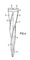
- a further advantageous embodiment is achieved in that the body 1 has a directional identification at its upper end, preferably in the form of radially extending notches or ribs 18 according to FIG. 4.
- the markers - are then advantageously inserted into the soil, that the direction marking 18 coincides with the respective limit or points in the direction of the adjacent marker points.
- a central depression 13, expediently a conical depression, for example for inserting a tip of a measuring rod, can be provided in the top of the head 7. You can also add additional markings or information such as "Verm.-Punkt" to this top.
- These latter configurations are particularly advantageous for marking devices which are intended for shallower depths in the ground.
- the permanent magnet 14, as explained above should be held by simple clamping, so that the permanent magnet can be easily removed and the markings underneath can be recognized.
- the permanent magnet 14 is non-detachably connected to the body by means of an adhesive.
- the use of the marking device according to the invention is not only advantageous in the field of marketing or measurement technology but also in many other cases, e.g. for marking particularly important points of systems installed in the ground, in particular oil, natural gas or district heating pipes, e.g. can mark those places where the pipe sections are connected by flanges, where the greatest risk of leakage is.
Landscapes
- Engineering & Computer Science (AREA)
- Architecture (AREA)
- Civil Engineering (AREA)
- Structural Engineering (AREA)
- Physics & Mathematics (AREA)
- General Physics & Mathematics (AREA)
- Radar, Positioning & Navigation (AREA)
- Remote Sensing (AREA)
- Geophysics And Detection Of Objects (AREA)
Priority Applications (1)
| Application Number | Priority Date | Filing Date | Title |
|---|---|---|---|
| EP82108017A EP0101757A1 (fr) | 1982-09-01 | 1982-09-01 | Dispositif pour le marquage d'un point de terrain arpenté dans le sol |
Applications Claiming Priority (1)
| Application Number | Priority Date | Filing Date | Title |
|---|---|---|---|
| EP82108017A EP0101757A1 (fr) | 1982-09-01 | 1982-09-01 | Dispositif pour le marquage d'un point de terrain arpenté dans le sol |
Publications (1)
| Publication Number | Publication Date |
|---|---|
| EP0101757A1 true EP0101757A1 (fr) | 1984-03-07 |
Family
ID=8189201
Family Applications (1)
| Application Number | Title | Priority Date | Filing Date |
|---|---|---|---|
| EP82108017A Ceased EP0101757A1 (fr) | 1982-09-01 | 1982-09-01 | Dispositif pour le marquage d'un point de terrain arpenté dans le sol |
Country Status (1)
| Country | Link |
|---|---|
| EP (1) | EP0101757A1 (fr) |
Cited By (4)
| Publication number | Priority date | Publication date | Assignee | Title |
|---|---|---|---|---|
| FR2580817A1 (fr) * | 1985-04-22 | 1986-10-24 | Gabriel Leonetout | Systeme de balisage et de detecteur de balises magnetiques |
| FR2584812A1 (fr) * | 1985-07-09 | 1987-01-16 | Neaume Robert | Dispositif de jalonnement des terrains |
| FR2701504A1 (fr) * | 1993-02-10 | 1994-08-19 | Millet Kennedy Andre | Pieu d'ancrage au sol. |
| FR2730749A1 (fr) * | 1995-02-16 | 1996-08-23 | Le Grall Bader Josiane Therese | Dispositif pour la reception d'un objet en forme de barre, par exemple d'un poteau, et procede pour la fabrication d'un tel dispositif |
Citations (9)
| Publication number | Priority date | Publication date | Assignee | Title |
|---|---|---|---|---|
| US2527681A (en) * | 1947-05-01 | 1950-10-31 | Charles T Wolfe | Marking device |
| DE1873783U (de) * | 1962-10-11 | 1963-06-12 | Erich Pfanstiel | Grenzstein mit eingelassenem ferromagnetischem teil. |
| DE1902185A1 (de) * | 1968-01-19 | 1969-09-25 | Serge Wolfcarius | Markstein u.dgl. |
| DE6939739U (de) * | 1969-10-13 | 1970-08-27 | Stanjek Dr Hubert | Markierungsvorrichtung |
| DE2307170A1 (de) * | 1973-02-14 | 1974-08-22 | Johannes Leptien | Grenzsteine mit eingelassenen magneten |
| DE7431704U (de) * | 1974-12-19 | Elsen J | Grenzstein | |
| US3916821A (en) * | 1972-06-19 | 1975-11-04 | Othmar W Pies | Magnetic marker assembly |
| FR2274025A2 (fr) * | 1974-06-07 | 1976-01-02 | Misson Robert | Perfectionnements aux bornes-jalons ou de signalisation |
| US4185424A (en) * | 1978-03-13 | 1980-01-29 | Phone-Ducs, Inc. | Molded plastic stake |
-
1982
- 1982-09-01 EP EP82108017A patent/EP0101757A1/fr not_active Ceased
Patent Citations (9)
| Publication number | Priority date | Publication date | Assignee | Title |
|---|---|---|---|---|
| DE7431704U (de) * | 1974-12-19 | Elsen J | Grenzstein | |
| US2527681A (en) * | 1947-05-01 | 1950-10-31 | Charles T Wolfe | Marking device |
| DE1873783U (de) * | 1962-10-11 | 1963-06-12 | Erich Pfanstiel | Grenzstein mit eingelassenem ferromagnetischem teil. |
| DE1902185A1 (de) * | 1968-01-19 | 1969-09-25 | Serge Wolfcarius | Markstein u.dgl. |
| DE6939739U (de) * | 1969-10-13 | 1970-08-27 | Stanjek Dr Hubert | Markierungsvorrichtung |
| US3916821A (en) * | 1972-06-19 | 1975-11-04 | Othmar W Pies | Magnetic marker assembly |
| DE2307170A1 (de) * | 1973-02-14 | 1974-08-22 | Johannes Leptien | Grenzsteine mit eingelassenen magneten |
| FR2274025A2 (fr) * | 1974-06-07 | 1976-01-02 | Misson Robert | Perfectionnements aux bornes-jalons ou de signalisation |
| US4185424A (en) * | 1978-03-13 | 1980-01-29 | Phone-Ducs, Inc. | Molded plastic stake |
Cited By (6)
| Publication number | Priority date | Publication date | Assignee | Title |
|---|---|---|---|---|
| FR2580817A1 (fr) * | 1985-04-22 | 1986-10-24 | Gabriel Leonetout | Systeme de balisage et de detecteur de balises magnetiques |
| FR2584812A1 (fr) * | 1985-07-09 | 1987-01-16 | Neaume Robert | Dispositif de jalonnement des terrains |
| EP0210101A1 (fr) * | 1985-07-09 | 1987-01-28 | Robert Neaume | Dispositif de jalonnement des terrains |
| US4696134A (en) * | 1985-07-09 | 1987-09-29 | Robert Neaume | Device for marking out land |
| FR2701504A1 (fr) * | 1993-02-10 | 1994-08-19 | Millet Kennedy Andre | Pieu d'ancrage au sol. |
| FR2730749A1 (fr) * | 1995-02-16 | 1996-08-23 | Le Grall Bader Josiane Therese | Dispositif pour la reception d'un objet en forme de barre, par exemple d'un poteau, et procede pour la fabrication d'un tel dispositif |
Similar Documents
| Publication | Publication Date | Title |
|---|---|---|
| DE8530749U1 (de) | Vorrichtung zum Befestigen von stabförmigen Gegenständen, insbesondere Pfosten, im Erdreich | |
| EP0101757A1 (fr) | Dispositif pour le marquage d'un point de terrain arpenté dans le sol | |
| DE69410285T2 (de) | Rasenähnliche kunststoffimplantate für markierung in rasenstücken | |
| EP0103780B1 (fr) | Marque souterraine, son procédé de fabrication et procédé pour l'introduire dans la terre | |
| DE2450691C3 (de) | Einschlag-Halterung für Straßenleitpfosten | |
| DE2415023A1 (de) | Im gelaende errichtbarer damm | |
| DE202007018693U1 (de) | Befestigungsvorrichtung für Straßenleitpfosten | |
| EP0498925B1 (fr) | Dispositif de connexion des tubes à installer dans des puits, remplis de bentonite | |
| CH674872A5 (fr) | ||
| DE202006008339U1 (de) | Bodenhülse | |
| DE102006056564B3 (de) | Befestigungseinrichtung für einen Blitzschutzmast oder eine Blitzschutzfangstange | |
| DE3804120A1 (de) | Vorrichtung zur abwehr von schnecken im gartenbau | |
| DE2336376C2 (de) | Verfahren zum Anbringen eines Markierungsorganes | |
| DE19910692C2 (de) | Elektronisches Gerät | |
| DE3240584C2 (fr) | ||
| DE3507219A1 (de) | Baumbeluefter | |
| DE8224181U1 (de) | Unterflurmarke | |
| DE19860739C2 (de) | Gießring für den Garten- und Landschaftsbau | |
| DE8814661U1 (de) | Vorrichtung für die unterirdische Vermarkung von Vermessungspunkten | |
| DE29805461U1 (de) | Vermarkungssystem | |
| DD286832A5 (de) | Verfahren und anordnung zum sichern von boeschungen | |
| DD205999A5 (de) | Markierer fuer die unterirdische markierung und eine neue anwendung fuer solch einen markierer | |
| DE6939739U (de) | Markierungsvorrichtung | |
| DE202025002237U1 (de) | Heckenschneidhilfe mit höhenverstellbaren Teleskopstangen und selbstspannendem, schnittresistentem Führungsseil | |
| DE29605751U1 (de) | Bohrstab zum Bohren eines Erdloches, für Vermarkungsarbeiten im Kataster- und Vermessungswesen, in das als unterirdische Vermarkung ein Hohlziegel oder Dränrohr eingesteckt wird |
Legal Events
| Date | Code | Title | Description |
|---|---|---|---|
| PUAI | Public reference made under article 153(3) epc to a published international application that has entered the european phase |
Free format text: ORIGINAL CODE: 0009012 |
|
| AK | Designated contracting states |
Designated state(s): AT BE CH DE FR GB IT LI LU NL SE |
|
| 17P | Request for examination filed |
Effective date: 19840907 |
|
| RAP1 | Party data changed (applicant data changed or rights of an application transferred) |
Owner name: FRINGS, URSULA C/O FRAU MATHILDE WOEGER |
|
| STAA | Information on the status of an ep patent application or granted ep patent |
Free format text: STATUS: THE APPLICATION HAS BEEN REFUSED |
|
| 18R | Application refused |
Effective date: 19880215 |