EP0103780B1 - Marque souterraine, son procédé de fabrication et procédé pour l'introduire dans la terre - Google Patents
Marque souterraine, son procédé de fabrication et procédé pour l'introduire dans la terre Download PDFInfo
- Publication number
- EP0103780B1 EP0103780B1 EP83108416A EP83108416A EP0103780B1 EP 0103780 B1 EP0103780 B1 EP 0103780B1 EP 83108416 A EP83108416 A EP 83108416A EP 83108416 A EP83108416 A EP 83108416A EP 0103780 B1 EP0103780 B1 EP 0103780B1
- Authority
- EP
- European Patent Office
- Prior art keywords
- housing
- core
- underground marker
- marker according
- coil
- Prior art date
- Legal status (The legal status is an assumption and is not a legal conclusion. Google has not performed a legal analysis and makes no representation as to the accuracy of the status listed.)
- Expired
Links
- 238000000034 method Methods 0.000 title claims description 8
- 239000003550 marker Substances 0.000 title claims 16
- 238000010276 construction Methods 0.000 title description 2
- 229910000859 α-Fe Inorganic materials 0.000 claims description 23
- 239000003990 capacitor Substances 0.000 claims description 12
- 125000006850 spacer group Chemical group 0.000 claims description 8
- 239000000853 adhesive Substances 0.000 claims description 2
- 230000001070 adhesive effect Effects 0.000 claims description 2
- 239000000696 magnetic material Substances 0.000 claims 4
- 239000004821 Contact adhesive Substances 0.000 claims 2
- 239000003086 colorant Substances 0.000 claims 1
- 239000002184 metal Substances 0.000 claims 1
- 238000002604 ultrasonography Methods 0.000 claims 1
- 238000005259 measurement Methods 0.000 abstract description 2
- 239000004575 stone Substances 0.000 description 5
- 238000004519 manufacturing process Methods 0.000 description 4
- 229920003002 synthetic resin Polymers 0.000 description 3
- 239000000057 synthetic resin Substances 0.000 description 3
- 238000002347 injection Methods 0.000 description 2
- 239000007924 injection Substances 0.000 description 2
- 239000004033 plastic Substances 0.000 description 2
- 239000002689 soil Substances 0.000 description 2
- 241000195955 Equisetum hyemale Species 0.000 description 1
- 230000005540 biological transmission Effects 0.000 description 1
- 238000005266 casting Methods 0.000 description 1
- 238000004870 electrical engineering Methods 0.000 description 1
- 239000000463 material Substances 0.000 description 1
- 230000005855 radiation Effects 0.000 description 1
- 230000008685 targeting Effects 0.000 description 1
Images

Classifications
-
- G—PHYSICS
- G01—MEASURING; TESTING
- G01C—MEASURING DISTANCES, LEVELS OR BEARINGS; SURVEYING; NAVIGATION; GYROSCOPIC INSTRUMENTS; PHOTOGRAMMETRY OR VIDEOGRAMMETRY
- G01C15/00—Surveying instruments or accessories not provided for in groups G01C1/00 - G01C13/00
- G01C15/02—Means for marking measuring points
- G01C15/04—Permanent marks; Boundary markers
Definitions
- the invention relates to underfloor marks to make it easier to find and locate locations and objects located below the surface, in particular for geodetic purposes.
- the invention further relates to a method for producing an underfloor mark.
- the invention also relates to a method for introducing an underfloor mark into the ground.
- boundary stone In geodesy, in land surveying and in other areas, the task is to pinpoint a location and make that location traceable.
- a boundary stone can also be implemented very deliberately. In order to be able to find the surveyed places anyway, one has already begun to bring an object into the ground under the boundary stone or in a very specific position, for example to push it into the ground to a certain depth. This object can then only be found by digging. This is a very tedious, time-consuming and often unsuccessful job.
- identification tags have been built which the skiers carry on their bodies (DE-AS 1 473 763).
- This identification tag is essentially a large frame coil embedded in plastic. This forms a passive resonant circuit. When targeting the frame coil with a transmitter, this energy is extracted. A negative amplitude arises. From this one can infer the position of and the distance to the frame coil and thus to the spilled person.
- a method for locating buried subjects DE-PS 1 249 416
- a transmitter is operated in a specific manner and is used to aim at an electromagnetic oscillating circuit carried in front of the buried person and to induce natural vibrations. The transmitter is switched off periodically. The vibrations emitted by the vibrating circuit carried by the spilled person are measured in the transmission pauses.
- a marking device to be introduced into the ground (US Pat. No. 3,836,842). It contains an oscillating circuit and acts as a passive circuit element. This device is placed in the ground a short distance below the surface. If you approach a point where one or more such devices are arranged with a transmitter and this is tuned to the frequency of the resonant circuit consisting of the coil and the capacitor, it is particularly damped. This can be seen. The position of the device is thus recognized.
- the invention has for its object to design an underfloor mark so that its location can be recognized particularly accurately.
- the underfloor mark according to the invention can also be used for automatically guiding or steering vehicles. For this purpose, it is laid in the floor of a factory or warehouse or in a driveway. Several underfloor marks are laid along a path to be driven by the vehicles. There are transmitters in the vehicles that recognize the underfloor marks. These transmitters then intervene in the steering of the vehicles so that they drive along the path marked with the underfloor markings.
- the housing can be filled with a synthetic resin.
- the core can also be fixed in a practical embodiment by rubber rings placed on its ends in the housing. In this case it is advisable to close the upper open end of the housing with a plug.
- the housing itself has the shape of a hollow cylinder with a cone placed on its lower end.
- a housing can be easily manufactured and, with the tip of the cone, inserted easily and with little effort into the soil to the desired depth.
- the core must be of different lengths.
- the production of cores of different lengths presents no particular difficulties. This is different with the housing molded from a plastic. An injection mold is very complex and therefore also expensive.
- an extension sleeve is inserted into the open end of the housing and the core is extended into the region of the extension sleeve.
- the extension sleeve is expediently glued into the housing. The extension sleeve thus enables the housing to be produced in one length with a single injection mold and, if necessary, extended with an extension sleeve.
- the cone has a larger diameter than the housing at its upper end, which has the larger diameter, in order to form a stepped shoulder.
- Devices or tools can be placed on this section from above to push the housing into the ground.
- the housing has ribs distributed over its circumference on its outside.
- the housing is mechanically fixed by these ribs.
- Another measure serves the same purpose, according to which the ribs and the housing are colored differently.
- FIG. 1 shows the cylindrical housing 12.
- the cone 14 is attached in one piece to its lower end.
- the ferrite core 16 is located in the housing 12.
- the self-supporting coil 18 is seated on this.
- the spacer 20 is placed on the lower end of the ferrite core 16 and the capacitor 22 is placed on its lower end, if appropriate glued.
- the coil 18 and the capacitor 22 are electrically connected to one another, which is not shown in detail.
- the cavity of the housing 12 is potted with a synthetic resin.
- the ferrite core 16, the coil 18, the spacer 20 and the capacitor 22 are tightly enclosed.
- the ferrite core 16 with the parts attached to it are fixed in the housing by rubber rings 24. In this case, the housing 12 is closed with a plug 26.
- the housing has 12 ribs 28 on its outside. These can have the semicircular cross-section shown in the top view or else another shape. They can also be larger than shown.
- the cone 14 projects radially beyond the housing 12. This results in the stepped shoulder 30.
- FIG. 1 also shows the short-circuit ring 36 screwed onto the housing 12. It can be screwed on and off. In the position in which the resonant circuit vibrates at the desired frequency, the short-circuit ring 36 is fixed. The illustration according to FIG. 1 is further explained in FIGS. 2 and 3.
- the lower end of the drive tube 32 stands on the shoulder 30.
- the underfloor mark is pressed or hammered into the ground with this drive tube 32.
- the drive tube 32 can rest on the ribs 28 with some clamping. If the drive tube cannot then be easily pulled off the ribs, the underfloor mark can be pushed out of the drive tube 32 with a stick. The underfloor mark is then free in the ground. Her interior is protected by the ribs 28. If the underfloor mark is touched with a spade or any tool, the ribs 28 can deform without damaging the electrical parts. If the ground is very hard or stony, a hole can be made or drilled before the underfloor mark is inserted.
- the underfloor mark can also be embedded in the ground using the well-known horsetail principle. Here, several tubes are telescoped. This pushes the underfloor mark into the ground.
- FIG. 6 shows the embodiment of the ferrite core 16, in which two disks 34 are arranged on the ferrite core 16 at a mutual spacing. Between these disks 34, the coil 18 is wound turn by turn onto the ferrite core 16.
- Fig. Further shows a ferrite rod 38. This is in a threaded hole tion screwed into one end of the ferrite core 16. By screwing the ferrite rod 38 on and off, the length and thus the inductance of the ferrite core 16 are changed. The natural frequency of the resonant circuit can also be set in this way.
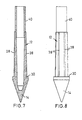
- FIG. 7 shows that a ferrite core 16 to be inserted into this extended housing is considerably longer than that according to FIG. 1. To simplify the illustration and to avoid repetitions, the ferrite core 16, the coil 18, etc. are not shown in FIG. 7.
- An underfloor mark lying in the ground can be located using a radio measuring device, generally called a detector.
- a detector detects an underfloor mark with its radiation area, its vibration amplitude changes.
- the type of change in the amplitude can be used to determine the exact distance to and therefore the position of the underfloor mark.
- the underfloor mark is embedded in the ground instead of or near boundary stones. It can also be used to mark pipes and cable routes. It can also be used to locate spilled material if it is in a non-magnetic medium.
Landscapes
- Physics & Mathematics (AREA)
- Engineering & Computer Science (AREA)
- General Physics & Mathematics (AREA)
- Radar, Positioning & Navigation (AREA)
- Remote Sensing (AREA)
- Geophysics And Detection Of Objects (AREA)
- Underground Or Underwater Handling Of Building Materials (AREA)
Claims (13)
Priority Applications (1)
| Application Number | Priority Date | Filing Date | Title |
|---|---|---|---|
| AT83108416T ATE29067T1 (de) | 1982-08-27 | 1983-08-26 | Unterflurmarke, verfahren zu deren herstellung und verfahren zu deren einbringung in das erdreich. |
Applications Claiming Priority (2)
| Application Number | Priority Date | Filing Date | Title |
|---|---|---|---|
| DE3231870 | 1982-08-27 | ||
| DE3231870A DE3231870C2 (de) | 1982-08-27 | 1982-08-27 | Unterflurmarke, Verfahren zu deren Herstellung und Verfahren zu deren Einbringung in das Erdreich |
Publications (2)
| Publication Number | Publication Date |
|---|---|
| EP0103780A1 EP0103780A1 (fr) | 1984-03-28 |
| EP0103780B1 true EP0103780B1 (fr) | 1987-08-19 |
Family
ID=6171822
Family Applications (1)
| Application Number | Title | Priority Date | Filing Date |
|---|---|---|---|
| EP83108416A Expired EP0103780B1 (fr) | 1982-08-27 | 1983-08-26 | Marque souterraine, son procédé de fabrication et procédé pour l'introduire dans la terre |
Country Status (4)
| Country | Link |
|---|---|
| EP (1) | EP0103780B1 (fr) |
| AT (1) | ATE29067T1 (fr) |
| DE (2) | DE3231870C2 (fr) |
| WO (1) | WO1984001025A1 (fr) |
Families Citing this family (5)
| Publication number | Priority date | Publication date | Assignee | Title |
|---|---|---|---|---|
| DK266284D0 (da) * | 1984-05-30 | 1984-05-30 | Willy Palle Pedersen | Fixpunktmarkeringsindretning |
| DK202090D0 (da) * | 1990-08-23 | 1990-08-23 | Willy Palle Pedersen | Markoer af elektromagnetisk resonanstype |
| FR2669727B1 (fr) * | 1990-11-23 | 1994-06-24 | Lebec Sa E Lts | Dispositif de bornage a usage topographique. |
| DE20204704U1 (de) | 2002-03-24 | 2002-07-25 | Krämer, Albert, Dipl.-Ing. (FH), 92559 Winklarn | Markierungsstein mit Metalleinlage |
| FR2907894B1 (fr) * | 2006-10-25 | 2008-12-19 | Jean Edouard Gissinger | "borne topographique" |
Family Cites Families (3)
| Publication number | Priority date | Publication date | Assignee | Title |
|---|---|---|---|---|
| DE855724C (de) * | 1951-02-09 | 1952-11-17 | Walter Brockmann | Vorrichtung zum Eintreiben von Markierungspfaehlen |
| US3836842A (en) * | 1973-01-22 | 1974-09-17 | Bell Canada Northern Electric | Encapsulated electrically resonant circuit and interrogating apparatus and method for finding same in various locations |
| IE53476B1 (en) * | 1981-10-08 | 1988-11-23 | Pedersen Willy Palle | A marker for substerranean marking and a novel application for such a marker |
-
1982
- 1982-08-27 DE DE3231870A patent/DE3231870C2/de not_active Expired
-
1983
- 1983-08-26 EP EP83108416A patent/EP0103780B1/fr not_active Expired
- 1983-08-26 WO PCT/DE1983/000150 patent/WO1984001025A1/fr not_active Ceased
- 1983-08-26 AT AT83108416T patent/ATE29067T1/de not_active IP Right Cessation
- 1983-08-26 DE DE8383108416T patent/DE3373136D1/de not_active Expired
Also Published As
| Publication number | Publication date |
|---|---|
| ATE29067T1 (de) | 1987-09-15 |
| DE3373136D1 (en) | 1987-09-24 |
| DE3231870C2 (de) | 1984-06-07 |
| WO1984001025A1 (fr) | 1984-03-15 |
| EP0103780A1 (fr) | 1984-03-28 |
| DE3231870A1 (de) | 1984-03-08 |
Similar Documents
| Publication | Publication Date | Title |
|---|---|---|
| DE69016035T2 (de) | Elektronische markierer mit vorbestimmter unterbrechung. | |
| DD300464A5 (de) | Verfahren und vorrichtung, die dauermagneten zur markierung, lokalisierung, suche und identifizierung versteckter objekte verwenden, wie z. b. eingelassene faseroptische kabel | |
| US11378535B2 (en) | Measuring probe for measuring in ground a parameter and a method for making such a probe | |
| DE1773237A1 (de) | Nahwirkungsschalter | |
| DE69616611T2 (de) | Ferritkernmarkierung | |
| EP0103780B1 (fr) | Marque souterraine, son procédé de fabrication et procédé pour l'introduire dans la terre | |
| DE3249105T (de) | Markierungsvorrichtung zur unterirdischen Markierung und eine neue Anwendung für eine solche Markierungsvorrichtung | |
| DE69407851T2 (de) | Verfahren zum Verlegen eines Produkts grosser Länge in das Erdreich und Vorrichtungen zu dessen Durchführung | |
| DE4027020C2 (de) | Verfahren und Vorrichtung zur Feststellung des Vorhandenseins von metallischen Bewehrungselementen im Innern eines Beton-Bauteils | |
| US3516171A (en) | Flexible grade stake with driving tool | |
| DE69907241T2 (de) | Nmr bohrlochmessvorrichtung | |
| DE3636322C2 (fr) | ||
| EP2131213A2 (fr) | Appareil d'excavation manuel | |
| EP2806070B1 (fr) | Dispositif et procédé de fabrication surveillée d'un corps d'injection haute pression | |
| EP0101757A1 (fr) | Dispositif pour le marquage d'un point de terrain arpenté dans le sol | |
| DE8224181U1 (de) | Unterflurmarke | |
| DE3526492A1 (de) | Vorrichtung zum auffinden von metall | |
| DE60102281T2 (de) | Verfahren zur Übertragung von Informationen über ein Bohrgestänge | |
| EP0780705A2 (fr) | Procédé de recherche et agencement des sondes pour localiser des objets souterrains | |
| DE102013010962A1 (de) | Ortungsgerät-Sondenanordnung | |
| DE202021106176U1 (de) | Bohrer zur Kampfmitteldetektion | |
| DE102016113136B4 (de) | Verfahren zur Charakterisierung eines metallischen Störkörpers | |
| EP1388615A1 (fr) | Méthode et appareil pour l'étude du sol | |
| DE102010032134B4 (de) | Verfahren zum Einbringen einer Bohrung in das Erdreich und Erdbohrvorrichtung | |
| EP1172668A2 (fr) | Dispositif et procédé de localisation et d'évaluation de dilatation d'objets ferromagnetiques dans un milieu nonferromagnetique |
Legal Events
| Date | Code | Title | Description |
|---|---|---|---|
| PUAI | Public reference made under article 153(3) epc to a published international application that has entered the european phase |
Free format text: ORIGINAL CODE: 0009012 |
|
| AK | Designated contracting states |
Designated state(s): AT BE CH DE FR GB IT LI LU NL SE |
|
| 17P | Request for examination filed |
Effective date: 19840928 |
|
| GRAA | (expected) grant |
Free format text: ORIGINAL CODE: 0009210 |
|
| AK | Designated contracting states |
Kind code of ref document: B1 Designated state(s): AT BE CH DE FR GB IT LI LU NL SE |
|
| REF | Corresponds to: |
Ref document number: 29067 Country of ref document: AT Date of ref document: 19870915 Kind code of ref document: T |
|
| PG25 | Lapsed in a contracting state [announced via postgrant information from national office to epo] |
Ref country code: LU Free format text: LAPSE BECAUSE OF NON-PAYMENT OF DUE FEES Effective date: 19870831 |
|
| REF | Corresponds to: |
Ref document number: 3373136 Country of ref document: DE Date of ref document: 19870924 |
|
| ITF | It: translation for a ep patent filed | ||
| ET | Fr: translation filed | ||
| PG25 | Lapsed in a contracting state [announced via postgrant information from national office to epo] |
Ref country code: DE Effective date: 19880503 |
|
| PLBE | No opposition filed within time limit |
Free format text: ORIGINAL CODE: 0009261 |
|
| STAA | Information on the status of an ep patent application or granted ep patent |
Free format text: STATUS: NO OPPOSITION FILED WITHIN TIME LIMIT |
|
| 26N | No opposition filed | ||
| PGFP | Annual fee paid to national office [announced via postgrant information from national office to epo] |
Ref country code: SE Payment date: 19890818 Year of fee payment: 7 |
|
| PGFP | Annual fee paid to national office [announced via postgrant information from national office to epo] |
Ref country code: LU Payment date: 19890830 Year of fee payment: 7 |
|
| PGFP | Annual fee paid to national office [announced via postgrant information from national office to epo] |
Ref country code: NL Payment date: 19890831 Year of fee payment: 7 Ref country code: AT Payment date: 19890831 Year of fee payment: 7 |
|
| PGFP | Annual fee paid to national office [announced via postgrant information from national office to epo] |
Ref country code: GB Payment date: 19891031 Year of fee payment: 7 |
|
| PGFP | Annual fee paid to national office [announced via postgrant information from national office to epo] |
Ref country code: CH Payment date: 19891122 Year of fee payment: 7 |
|
| PG25 | Lapsed in a contracting state [announced via postgrant information from national office to epo] |
Ref country code: GB Effective date: 19900826 Ref country code: AT Effective date: 19900826 |
|
| PG25 | Lapsed in a contracting state [announced via postgrant information from national office to epo] |
Ref country code: SE Effective date: 19900827 |
|
| PG25 | Lapsed in a contracting state [announced via postgrant information from national office to epo] |
Ref country code: LI Effective date: 19900831 Ref country code: CH Effective date: 19900831 |
|
| PG25 | Lapsed in a contracting state [announced via postgrant information from national office to epo] |
Ref country code: NL Effective date: 19910301 |
|
| NLV4 | Nl: lapsed or anulled due to non-payment of the annual fee | ||
| GBPC | Gb: european patent ceased through non-payment of renewal fee | ||
| REG | Reference to a national code |
Ref country code: CH Ref legal event code: PL |
|
| ITTA | It: last paid annual fee | ||
| PGFP | Annual fee paid to national office [announced via postgrant information from national office to epo] |
Ref country code: BE Payment date: 19930906 Year of fee payment: 11 |
|
| PGFP | Annual fee paid to national office [announced via postgrant information from national office to epo] |
Ref country code: FR Payment date: 19940817 Year of fee payment: 12 |
|
| PG25 | Lapsed in a contracting state [announced via postgrant information from national office to epo] |
Ref country code: BE Effective date: 19940831 |
|
| EUG | Se: european patent has lapsed |
Ref document number: 83108416.5 Effective date: 19910410 |
|
| BERE | Be: lapsed |
Owner name: EBINGER KLAUS Effective date: 19940831 |
|
| PG25 | Lapsed in a contracting state [announced via postgrant information from national office to epo] |
Ref country code: FR Effective date: 19960430 |
|
| REG | Reference to a national code |
Ref country code: FR Ref legal event code: ST |