EP0101906A2 - Verfahren und Vorrichtung zur kontrollierten Herabsetzung der Temperatur von Embryos und ihre Aufbewahrung in tiefgefrorenem Zustand - Google Patents
Verfahren und Vorrichtung zur kontrollierten Herabsetzung der Temperatur von Embryos und ihre Aufbewahrung in tiefgefrorenem Zustand Download PDFInfo
- Publication number
- EP0101906A2 EP0101906A2 EP83107185A EP83107185A EP0101906A2 EP 0101906 A2 EP0101906 A2 EP 0101906A2 EP 83107185 A EP83107185 A EP 83107185A EP 83107185 A EP83107185 A EP 83107185A EP 0101906 A2 EP0101906 A2 EP 0101906A2
- Authority
- EP
- European Patent Office
- Prior art keywords
- chamber
- embryos
- gaseous medium
- temperature
- heat transfer
- Prior art date
- Legal status (The legal status is an assumption and is not a legal conclusion. Google has not performed a legal analysis and makes no representation as to the accuracy of the status listed.)
- Withdrawn
Links
Images
Classifications
-
- F—MECHANICAL ENGINEERING; LIGHTING; HEATING; WEAPONS; BLASTING
- F25—REFRIGERATION OR COOLING; COMBINED HEATING AND REFRIGERATION SYSTEMS; HEAT PUMP SYSTEMS; MANUFACTURE OR STORAGE OF ICE; LIQUEFACTION SOLIDIFICATION OF GASES
- F25B—REFRIGERATION MACHINES, PLANTS OR SYSTEMS; COMBINED HEATING AND REFRIGERATION SYSTEMS; HEAT PUMP SYSTEMS
- F25B21/00—Machines, plants or systems, using electric or magnetic effects
- F25B21/02—Machines, plants or systems, using electric or magnetic effects using Peltier effect; using Nernst-Ettinghausen effect
-
- A—HUMAN NECESSITIES
- A01—AGRICULTURE; FORESTRY; ANIMAL HUSBANDRY; HUNTING; TRAPPING; FISHING
- A01N—PRESERVATION OF BODIES OF HUMANS OR ANIMALS OR PLANTS OR PARTS THEREOF; BIOCIDES, e.g. AS DISINFECTANTS, AS PESTICIDES OR AS HERBICIDES; PEST REPELLANTS OR ATTRACTANTS; PLANT GROWTH REGULATORS
- A01N1/00—Preservation of bodies of humans or animals, or parts thereof
- A01N1/10—Preservation of living parts
-
- A—HUMAN NECESSITIES
- A01—AGRICULTURE; FORESTRY; ANIMAL HUSBANDRY; HUNTING; TRAPPING; FISHING
- A01N—PRESERVATION OF BODIES OF HUMANS OR ANIMALS OR PLANTS OR PARTS THEREOF; BIOCIDES, e.g. AS DISINFECTANTS, AS PESTICIDES OR AS HERBICIDES; PEST REPELLANTS OR ATTRACTANTS; PLANT GROWTH REGULATORS
- A01N1/00—Preservation of bodies of humans or animals, or parts thereof
- A01N1/10—Preservation of living parts
- A01N1/14—Mechanical aspects of preservation; Apparatus or containers therefor
- A01N1/142—Apparatus
- A01N1/144—Apparatus for temperature control, e.g. refrigerators or freeze-drying apparatus
- A01N1/145—Stationary or portable vessels generating cryogenic temperatures, e.g. liquid nitrogen baths
-
- F—MECHANICAL ENGINEERING; LIGHTING; HEATING; WEAPONS; BLASTING
- F25—REFRIGERATION OR COOLING; COMBINED HEATING AND REFRIGERATION SYSTEMS; HEAT PUMP SYSTEMS; MANUFACTURE OR STORAGE OF ICE; LIQUEFACTION SOLIDIFICATION OF GASES
- F25B—REFRIGERATION MACHINES, PLANTS OR SYSTEMS; COMBINED HEATING AND REFRIGERATION SYSTEMS; HEAT PUMP SYSTEMS
- F25B2321/00—Details of machines, plants or systems, using electric or magnetic effects
- F25B2321/02—Details of machines, plants or systems, using electric or magnetic effects using Peltier effects; using Nernst-Ettinghausen effects
- F25B2321/021—Control thereof
-
- F—MECHANICAL ENGINEERING; LIGHTING; HEATING; WEAPONS; BLASTING
- F25—REFRIGERATION OR COOLING; COMBINED HEATING AND REFRIGERATION SYSTEMS; HEAT PUMP SYSTEMS; MANUFACTURE OR STORAGE OF ICE; LIQUEFACTION SOLIDIFICATION OF GASES
- F25D—REFRIGERATORS; COLD ROOMS; ICE-BOXES; COOLING OR FREEZING APPARATUS NOT OTHERWISE PROVIDED FOR
- F25D17/00—Arrangements for circulating cooling fluids; Arrangements for circulating gas, e.g. air, within refrigerated spaces
- F25D17/04—Arrangements for circulating cooling fluids; Arrangements for circulating gas, e.g. air, within refrigerated spaces for circulating air, e.g. by convection
- F25D17/06—Arrangements for circulating cooling fluids; Arrangements for circulating gas, e.g. air, within refrigerated spaces for circulating air, e.g. by convection by forced circulation
-
- F—MECHANICAL ENGINEERING; LIGHTING; HEATING; WEAPONS; BLASTING
- F25—REFRIGERATION OR COOLING; COMBINED HEATING AND REFRIGERATION SYSTEMS; HEAT PUMP SYSTEMS; MANUFACTURE OR STORAGE OF ICE; LIQUEFACTION SOLIDIFICATION OF GASES
- F25D—REFRIGERATORS; COLD ROOMS; ICE-BOXES; COOLING OR FREEZING APPARATUS NOT OTHERWISE PROVIDED FOR
- F25D2600/00—Control issues
- F25D2600/06—Controlling according to a predetermined profile
Definitions
- This invention relates to cryogenic systems; and more particularly relates to a method and apparatus for regulating the rate of cooling and temperature level of embryos to be maintained in a frozen or cryogenic state.
- Cryogenic systems are finding an increasing application in the low temperature storage or preservation of materials; for instance, biological elements or specimens, such as animal or human embryos, tissues and blood cells.
- the present invention is directed to the controlled reduction of temperature, or cooling rate, in order to place those materials in a frozen state at extremely low temperatures. It is important to regulate the rate of cooling of many articles, particularly embryos, tissue, blood cells and the like in order to reduce uneven temperatures within the chamber and avoid adverse effects on the materials to be preserved.
- Liquid nitrogen has been in use in the cooling and storage of articles in a cryogenic state because of its ability to drop the temperature to extremely low levels of the order of -35°C and less, but liquid nitrogen is expensive, lacks close control over chamber temperature and its cooling rate.
- the present invention provides apparatus for reducing the temperature of embryos and the like at a controlled and predetermined rate, comprising a cooling chamber and support means for removably suspending said embryos in said cooling chamber, gaseous medium circulating means for recirculating a gaseous medium along a closed path through said chamber with said embryos in the path of circulation of said gaseous medium, heat exchange means including heat transfer elements positioned in the path of flow of said gaseous medium, and means for regulating the rate of heat transfer and cooling rate of said gaseous medium circulated through said chamber.
- the present invention also provides a method of freezing embryos at a controlled rate from room temperature to cryogenic temperatures of the order of -50 0 C comprising the steps of providing an insulated chamber in which said embryos are removably supported, positioning a heat transfer medium in said chamber, circulating a gaseous medium through said chamber successively across said heat transfer medium and said embryos wherein said gaseous medium is air which is forced under presssure along a closed path in an axial direction first along the inner wall surfaces of said chamber and to return along the central axis of said chamber into direct contact with said heat transfer medium followed by passing across said embryos, and programming the rate of cooling of said gaseous medium by regulating the temperature of said heat transfer medium.
- the present invention provides programmed control over the reduction in temperature of biological specimens in such a way that air can be employed as a gaseous medium in reducing the temperature of the articles in the temperature range of O O C to as low as -50°C, and further provides a cryogenic system for cooling articles to extremely low temperatures having a chamber of a particular construction for removable suspension of the articles, and in which the circulation of a gaseous medium with respect to the articles as well as the controlled reduction in temperature of the gaseous medium is such as to maintain close, accurate control over the actual rate of temperature drop of the articles themselves.
- a housing defining an insulated cooling chamber is employed in association with support means for removably _suspending the embryos within said chamber.
- Gaseous medium circulating means are operative to circulate a gaseous medium along a closed path through the chamber such that the embryos are disposed in the path of circulation of the gaseous medium, and heat exchange means including a heat transfer medium is positioned in the path of flow of the gaseous medium together with a temperature sensor so that the rate of cooling may be programmed and regulated automatically by correlation of the temperature sensing means with the heat exchange medium.
- air is circulated by a blower around the inner walls of the chamber, against the support means which holds the embryos in place, then is reversed in direction to pass centrally of the chamber back into the suction side of the blower.
- Extremely close, programmed control over the cooling rate is established by regulating the voltage applied to a reverse thermocouple forming a part of the heat exchange means which has the heat transfer medium intruding into the chamber adjacent to the chamber walls so as to be in the path of flow of the air and the temperature sensor is located in the path of flow of air past the embryos preliminary to its return into the suction side of the blower.
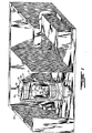
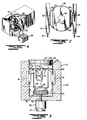
- a preferred cryogenic system broadly comprises a housing 10 which defines an insulated cooling chamber 12.
- a removable support member 14 is insertable into one end of the chamber 12 and includes a plurality of embryo support canes 15 of conventional construction.
- a gaseous medium preferably air
- the blower will maintain a path of circulation axially along the chamber wall against the upper support 14 where it is reversed and flows downwardly along the central area of the chamber across the encapsulated embryos.
- Heat exchangers 18 are in the form of thermoelectric devices, each including a reverse thermocouple 19 to which voltage is applied by a power source 20, and a heat transfer medium in the form of convoluted fins 22 intrude into diametrically opposed wall portions of the chamber 12 from communication with a heat exchanger or plenum 21, the fins 22 being disposed directly in the path of the air flow from the blower 16.
- the heat exchanger contains a suitable coolant, such as water, which is circulated into the plenums or heat sinks 21 in heat exchange relation to the fins 22 from a supply tank 23.
- a suitable coolant such as water
- Baffle plates 24 extend longitudinally of the chamber in spaced relation inwardly of the heat transfer fins 22 and terminate just short of the upper end of support member 14 to aid in regulating air circulation through the outside areas 26 formed between the baffle plates 24 and chamber 12 so as to pass in direct heat transfer relation to the fins 22.
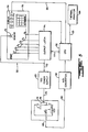
- a temperature sensor 28 is disposed in the return path of air flow and is electrically connected into an electric control circuit 30 shown in Figure 5.
- the circuit 30 includes a microprocessor represented at 32 in a closed feedback loop which in response to the rate of temperature reduction will operate through the power source 20 to regulate the amount of voltage applied to the reverse thermocouple 19 in a manner to be hereinafter described.
- the housing 10 is positioned in upright relation within an outside enclosure represented at 33.
- the housing 10 is of generally cylindrical configuration having an insulated outer wall 34 which may suitbly be composed of a polyurethane foam insulation material, the upper end normally enclosed by an insulated cover 35 of generally circular configuration.
- the cover has an outer rim 36 overlapping the upper end of the cylindrical outer wall 34 and a central body 37 which projects into the chamber for a limited distance and is provided with one or more annular sealing rings 38 dimensioned to sealingly engage the inner surface of the wall 34.
- Spaced inwardly of the body 37 within the chamber is a radially inwardly directed rib 40 upon which the intermediate support plate 14 is seated.
- the plate 14 is of circular configuration and has spaced openings 42 sized for close-fitting insertion of the canes 15.
- the canes 15 may be of the type formed of open or slotted tubes having ledges 44 at longitudinally spaced intervals. The embryos are encapsulated in a well-known manner within vials 45 and are positioned on each ledge 44 so as to be directly exposed to the return air flowing thereacross.
- the blower 16 is preferably a squirrel cage fan supported in the base of the chamber on an upwardly directed drive shaft 50 of motor 52 which is disposed externally of and beneath the chamber 12.
- the shaft 50 extends upwardly through the insulated base, and the motor 52 is positioned on a heat sink in the form of aluminum fins 53 so as to minimize heating of the motor or its shaft which could otherwise be transmitted into the interior of the chamber 12.
- the blower 16 discharges air in an outward radial direction through its outer periphery 54 and has an upper return at its suction side 55.
- the baffle plates 24 are preferably mounted on an annular support plate or base 58 which is sized to correspond to the diameter of the chamber except at diametrically opposed flatted edges 59 where the baffle plates 24 extend upwardly in diametrically opposed relation to one another and thus form clearance spaces or areas 26 for upward movement of the air from the fan 16.
- the temperature sensor 28 is suspended on the base 58 to project into the hollow central opening 60 in the base in the path of flow of air which is returned along the centre of the chamber into the inlet 55.
- thermoelectric device includes convoluted aluminum fins 22 attached to the inner wall surfaces of each of the plenums 21 which surround the thermocouple assemblies 19 of the thermoelectric devices 18, the inner surfaces of the air fins 22 defining diametrically opposed wall surfaces of the chamber 12 with their convolutions extending parallel to the direction of air flow.
- a source of water coolant 23 includes conduits 64 extending from the supply to one plenum or heat sink 21, an intermediate conduit 65 interconnecting the heat sinks 21 to conduct the coolant from the first to the seond heat sink 21, and a return line 66 extending from the second heat sink 21 back to the coolant source.
- the heat sinks are generally elongated and rectangular and each contains a thermocouple assembly 19 which is preferably of the reverse thermocouple type, such as, Model 806-1008-01 manufactured by Cambion of Cambridge, Massachusetts, U.S.A., a two-stage device having a 31/186 couple ratio capable of operating over a temperature range of -550 C to +124°C.
- Each heat sink or plenum 21 is a liquid cooled exchanger used to remove waste heat from the thermoelectric component, and ordinary tap water may be used as the cooling fluid.
- the temperature sensor may be a resistance thermometer, also available from Cambion of Cambridge, Massachusetts and has suitable leads 68 which extend into the control circuit as shown in Figure 5.
- cryogenic system of the present invention may be best described in relation to the electrical control circuit as shown in Figure 5 wherein the power supply 20 directs an output signal over line 70 to the thermoelectric devices 18.
- the power supply is regulated by a demand signal over line 72 from output latch circuit 74 with reverse thermocouples, the greater the rate of cooling required, the more voltage is applied to the reverse thermocouples 19.
- the cooling rate is preselected and programmed into microprocessor 32 which applies control signals to the output latch circuit 74 through the display panel 78.
- the display panel includes display lights 79 to numerically indicate various parameters or working conditions in the cryogenic chamber, such as the rate of cooling and temperature level at any given point in time.
- a typical cooling rate programmed into the microprocessor is represented on the display panel 78 and indicates various temperature levels over given periods of time to be reached by the cryogenic chamber. For instance, this temperature range may extend from a starting point of 40° down to -35 0 C or lower. Also programmed into the microprocessor is the desired cooling rate as designated at T l through T6 between each temperature level including dwell periods to maintain the temperature at a constant level over a limited period of time followed by a reduction to a next temperature.
- the temperature sensed in the chamber 12 by sensor 28 is applied to an analog signal over line 80 to an analog-to-digital converter 82 which conditions and converts the analog signals into digital pulses applied to the microprocessor 76.
- the microprocessor compares those signals with the programmed temperature level and directs correction signals over line 77 to the latch circuit 74.
- the signals are also directed over line 83 to a thermal printer 84 and over line 85 to LED display 79. If the temperature sensed in the chamber departs from the preselected temperature level programmed into the microprocessor 32, the microprocessor 32 will generate a correction signal either to increase or reduce the applied power to the thermocouples 19.
- T l may represent a drop in temperature from 40 0 C to 20°C at T 2 .
- the temperature is held for a controlled time interval, such as, of the order of five minutes.
- the temperature is dropped at the rate of 1°C per minute to -7 0 C, and is held at that level for another controlled period, such as five minutes as at T 4 .
- the temperature is dropped at the rate of -3 0 C per minute to -30°C as represented at T6 .
- the temperature is constantly monitored both with respect to temperature level and cooling rate to be sure that it follows the programmed rate of cooling. If the temperature or rate of cooling varies from that programme, a correction signal is applied either to reduce or increase the applied voltage. For instance, if the temperature should be above the programme level, the voltage is increased and if it should be below the programme level the voltage is reduced.
- the cryogenic chamber can reduce the embryos to a temperature level as low as -50°C, followed by removal of the embryos from the chamber and placement in a nitrogen chamber to reduce their temperature still further. To this end, all that is necessary is to remove the outer cover 35 followed by removal of the intermediate lid 14 and suspended embryos. Then a new batch of embryos may be suspended in the lid and replaced in the chamber. During the replacement interval, the fan 16 operates as well as the thermoelectric devices 18 so that the next batch of embryos will undergo immediate preliminary cooling as soon as they are placed in the chamber and the outer cover is repositioned.
- the demand light 75 on the display panel indicates the amount of voltage applied to the thermoelectric devices. As the voltage level increases, the demand light intensity will increase, and the operator may want to modify the programme to reduce the amount of voltage supply, or vice versa, depending upon the particular conditions of the chamber as indicated by the LED display 79.
- the thermal printer 84 operates in a well-known manner to provide a hard copy or printed record of the temperature programme selected and the actual performance of the cryogenic device during a run or cycle.
- a keyboard 86 will permit a variety of temperature programmes to be entered by the operator for the application desired, such as freezing of animal embryos, human liver tissue, etc.
- the keyboard may be numeric or alphanumeric to enter the desired programme in regulating the rate of reduction of temperature throughout a given cycle.
- the amperage or current level can be monitored for the power supplies 20 for optimum performance and cooling capacity, since the amperage will change in the thermoelectric devices by the changes in temperature.
- the fan 16 when operating in the range of 3,000 rpm with an output or air flow approximating 100 cubic feet per minute (47.2 litres per second) can be used in cattle embryo freezing systems where the chamber 12 is given a diameter of the order of 4" (10 cms) and a length of height of the order of 12' (30 cms) between the base 58 and the movable support plate 14.
Landscapes
- Engineering & Computer Science (AREA)
- Life Sciences & Earth Sciences (AREA)
- Zoology (AREA)
- Dentistry (AREA)
- General Health & Medical Sciences (AREA)
- Wood Science & Technology (AREA)
- Health & Medical Sciences (AREA)
- Environmental Sciences (AREA)
- Physics & Mathematics (AREA)
- Mechanical Engineering (AREA)
- Thermal Sciences (AREA)
- General Engineering & Computer Science (AREA)
- Agricultural Chemicals And Associated Chemicals (AREA)
- Apparatus Associated With Microorganisms And Enzymes (AREA)
Applications Claiming Priority (2)
| Application Number | Priority Date | Filing Date | Title |
|---|---|---|---|
| US402840 | 1982-07-29 | ||
| US06/402,840 US4459825A (en) | 1982-07-29 | 1982-07-29 | Apparatus for controlled reduction in temperature and preservation of embryos in a cryogenic state |
Publications (2)
| Publication Number | Publication Date |
|---|---|
| EP0101906A2 true EP0101906A2 (de) | 1984-03-07 |
| EP0101906A3 EP0101906A3 (de) | 1984-10-17 |
Family
ID=23593485
Family Applications (1)
| Application Number | Title | Priority Date | Filing Date |
|---|---|---|---|
| EP83107185A Withdrawn EP0101906A3 (de) | 1982-07-29 | 1983-07-22 | Verfahren und Vorrichtung zur kontrollierten Herabsetzung der Temperatur von Embryos und ihre Aufbewahrung in tiefgefrorenem Zustand |
Country Status (4)
| Country | Link |
|---|---|
| US (1) | US4459825A (de) |
| EP (1) | EP0101906A3 (de) |
| JP (1) | JPS5951201A (de) |
| GB (1) | GB2135035B (de) |
Cited By (8)
| Publication number | Priority date | Publication date | Assignee | Title |
|---|---|---|---|---|
| EP0181235A3 (en) * | 1984-11-09 | 1987-04-29 | Freeze Control Pty. Ltd. | Cryosystem for biological material |
| US4712607A (en) * | 1984-11-09 | 1987-12-15 | Freeze Control Pty. Ltd. | Cryosystem for biological material |
| CH672834A5 (de) * | 1987-01-19 | 1989-12-29 | Agrogen Stiftung | |
| WO1995022727A1 (en) * | 1994-02-21 | 1995-08-24 | Hopital Cantonal Universitaire De Geneve | Transportable refrigerating container |
| EP0843137A1 (de) * | 1996-11-18 | 1998-05-20 | Thermovonics Co., Ltd | Thermoelektrischer Kühlschrank |
| EP0927860A1 (de) * | 1996-11-07 | 1999-07-07 | Hyppocampus S.r.l. | Kühler für Flüssigkeiten und dergleichen oder für Feststoffe |
| EP1793185A3 (de) * | 2005-12-02 | 2008-05-14 | Planner Plc. | Gefrierschrank mit gesteuerter Kühlrate für biologisches Material |
| CN103155913A (zh) * | 2013-03-19 | 2013-06-19 | 中国农业科学院作物科学研究所 | 一种小麦幼胚的冷冻储藏方法 |
Families Citing this family (22)
| Publication number | Priority date | Publication date | Assignee | Title |
|---|---|---|---|---|
| US4869250A (en) * | 1985-03-07 | 1989-09-26 | Thermacor Technology, Inc. | Localized cooling apparatus |
| DE3517518A1 (de) * | 1985-05-15 | 1986-11-20 | Fa. Carl Zeiss, 7920 Heidenheim | Kuehlkammer zum bearbeiten von objekten fuer mikroskopische oder elektronenmikroskopische untersuchungen |
| US5125237A (en) * | 1987-11-12 | 1992-06-30 | Louis P. Saia, III | Portable self-contained cooler/freezer apparatus for use on airplanes, common carrier type unrefrigerated truck lines, and the like |
| US4991402A (en) * | 1987-11-12 | 1991-02-12 | Saia Iii Louis P | Portable self-contained cooler/freezer apparatus for use on common carrier type unrefrigerated truck lines and the like |
| US4825666A (en) * | 1987-11-12 | 1989-05-02 | Saia Iii Louis P | Portable self-contained cooler/freezer apparatus for use on common carrier type unrefrigerated truck lines and the like |
| US4757692A (en) * | 1987-12-14 | 1988-07-19 | Mcdonald Gordon K | Embryo freezer |
| US4872589A (en) * | 1988-04-18 | 1989-10-10 | Englehart John D | Liner/insert for refrigerated container |
| US5297234A (en) * | 1990-05-09 | 1994-03-22 | Lifesource Advanced Blood Bank Systems, Inc. | Method and apparatus for the rapid thermal processing of transfusion fluid |
| US5623105A (en) * | 1992-10-21 | 1997-04-22 | Prolong Systems, Inc. | Oxygen/carbon dioxide sensor and controller for a refrigerated controlled atmosphere shipping container |
| US5363670A (en) * | 1993-04-19 | 1994-11-15 | Anthony Bartilucci | Self-contained cooler/freezer apparatus |
| US5388429A (en) * | 1993-06-09 | 1995-02-14 | Low Temp Industries, Inc. | Cooling equipment |
| DE4406145C2 (de) * | 1994-02-25 | 1996-07-25 | Binder Peter Michael | Laborkühlschrank mit Umluft-Temperierung, insbesondere Kühlbrutschrank |
| US5456164A (en) * | 1995-01-10 | 1995-10-10 | Donghwan Ind. Corp. | Kimchi fermentation or cool storage system using a thermoelectric module |
| GB2331838A (en) * | 1997-11-24 | 1999-06-02 | Coolbox | Portable,thermoelectric,temperature controlled receptacles. |
| US6226997B1 (en) * | 1999-12-07 | 2001-05-08 | Cryo-Cell International, Inc. | Method and device for maintaining temperature integrity of cryogenically preserved biological samples |
| JP5043199B2 (ja) * | 2007-11-09 | 2012-10-10 | プラクスエア・テクノロジー・インコーポレイテッド | 生物材料を制御された速度で冷凍する方法及びシステム |
| US8099967B2 (en) * | 2008-04-10 | 2012-01-24 | Yu Jia | Portable rack carrier device and the method of use |
| US8537018B2 (en) | 2010-06-09 | 2013-09-17 | Thermo Fisher Scientific (Asheville) Llc | Refrigeration system management and information display |
| DE102011079908A1 (de) * | 2011-07-27 | 2013-01-31 | Peter Lüpges | Tragbare Temperiervorrichtung für Medikamente |
| DE102012024105A1 (de) * | 2012-12-10 | 2014-06-12 | Fraunhofer-Gesellschaft zur Förderung der angewandten Forschung e.V. | Kryo-Lagereinrichtung und Verfahren zu deren Betrieb |
| JP5988905B2 (ja) * | 2013-03-22 | 2016-09-07 | 大陽日酸株式会社 | サブゼロ処理装置 |
| JP6653200B2 (ja) * | 2016-03-25 | 2020-02-26 | 大陽日酸株式会社 | 生体試料の凍結装置 |
Family Cites Families (18)
| Publication number | Priority date | Publication date | Assignee | Title |
|---|---|---|---|---|
| GB757018A (en) * | 1954-12-28 | 1956-09-12 | Union Stock Yard & Transit Co Chicago | Improvements in or relating to method and apparatus for chilling and refrigerating perishable products |
| US3174291A (en) * | 1959-05-11 | 1965-03-23 | Whirlpool Co | Temperature regulating apparatus |
| US3088290A (en) * | 1960-01-04 | 1963-05-07 | Philco Corp | Preservation of foods by refrigeration |
| US3092974A (en) * | 1960-07-21 | 1963-06-11 | Union Carbide Corp | Method and apparatus for controlled freezing of biologicals |
| FR1296171A (fr) * | 1961-07-18 | 1962-06-15 | Union Carbide Corp | Procédé et appareil de traitement thermique de substances biologiques |
| US3177670A (en) * | 1963-05-17 | 1965-04-13 | Borg Warner | Thermoelectric refrigerator |
| FR1369444A (fr) * | 1963-06-29 | 1964-08-14 | Rech Scient Et Tech Outre Mer | Chambre climatisée et ses applications |
| US3407120A (en) * | 1965-12-23 | 1968-10-22 | Abbott Lab | Tissue culture propagator and method |
| GB1284077A (en) * | 1968-10-18 | 1972-08-02 | British Petroleum Co | Process and apparatus for the cultivation of micro-organisms |
| DE1806085B2 (de) * | 1968-10-25 | 1972-04-20 | Siemens AG, 1000 Berlin u. 8000 München | Kuehlschrank mit peltier-kuehlbloecken |
| FR2112598A5 (de) * | 1970-11-02 | 1972-06-23 | Richard Jean Paul | |
| BE791951A (fr) * | 1971-12-10 | 1973-03-16 | Int Promotion Eng Sa | Perfectionnements aux moyens de production de froid et applications |
| DE2511038C2 (de) * | 1974-03-18 | 1982-04-01 | Hans Dr.-Ing. Männedorf Müller | Vorrichtung zum Kühlen und Belüften der Substratflüssigkeit in Reaktoren für mikrobiologische Stoffumsetzungen. |
| US4036699A (en) * | 1976-02-02 | 1977-07-19 | Phillips Petroleum Company | Fermentation apparatus and method |
| US4030314A (en) * | 1976-04-07 | 1977-06-21 | John Frederick Strehler | Method and apparatus for preserving biological materials |
| US4238337A (en) * | 1979-02-09 | 1980-12-09 | Walter Todd Peters | Methane gas producer using biological decomposition of waste matter |
| DK178679A (da) * | 1979-05-01 | 1980-11-02 | Nielsen H | Fremgangsmaade til nedfrysning af tyresaed og apparat til udoevelse af fremgangsmaaden |
| SE7910091L (sv) * | 1979-12-07 | 1981-06-08 | Supercool Ab | Anordning for kall- eller varmforvaring |
-
1982
- 1982-07-29 US US06/402,840 patent/US4459825A/en not_active Expired - Fee Related
-
1983
- 1983-07-22 EP EP83107185A patent/EP0101906A3/de not_active Withdrawn
- 1983-07-25 GB GB08319956A patent/GB2135035B/en not_active Expired
- 1983-07-28 JP JP58138639A patent/JPS5951201A/ja active Pending
Cited By (10)
| Publication number | Priority date | Publication date | Assignee | Title |
|---|---|---|---|---|
| EP0181235A3 (en) * | 1984-11-09 | 1987-04-29 | Freeze Control Pty. Ltd. | Cryosystem for biological material |
| US4712607A (en) * | 1984-11-09 | 1987-12-15 | Freeze Control Pty. Ltd. | Cryosystem for biological material |
| CH672834A5 (de) * | 1987-01-19 | 1989-12-29 | Agrogen Stiftung | |
| EP0275829A3 (en) * | 1987-01-19 | 1990-04-11 | Agrogen-Stiftung | Low-temperature freezing device for samples of biological material enclosed in containers |
| WO1995022727A1 (en) * | 1994-02-21 | 1995-08-24 | Hopital Cantonal Universitaire De Geneve | Transportable refrigerating container |
| EP0927860A1 (de) * | 1996-11-07 | 1999-07-07 | Hyppocampus S.r.l. | Kühler für Flüssigkeiten und dergleichen oder für Feststoffe |
| EP0843137A1 (de) * | 1996-11-18 | 1998-05-20 | Thermovonics Co., Ltd | Thermoelektrischer Kühlschrank |
| EP1793185A3 (de) * | 2005-12-02 | 2008-05-14 | Planner Plc. | Gefrierschrank mit gesteuerter Kühlrate für biologisches Material |
| CN103155913A (zh) * | 2013-03-19 | 2013-06-19 | 中国农业科学院作物科学研究所 | 一种小麦幼胚的冷冻储藏方法 |
| CN103155913B (zh) * | 2013-03-19 | 2014-08-13 | 中国农业科学院作物科学研究所 | 一种小麦幼胚的冷冻储藏方法 |
Also Published As
| Publication number | Publication date |
|---|---|
| GB2135035A (en) | 1984-08-22 |
| GB8319956D0 (en) | 1983-08-24 |
| US4459825A (en) | 1984-07-17 |
| GB2135035B (en) | 1986-12-03 |
| EP0101906A3 (de) | 1984-10-17 |
| JPS5951201A (ja) | 1984-03-24 |
Similar Documents
| Publication | Publication Date | Title |
|---|---|---|
| EP0101906A2 (de) | Verfahren und Vorrichtung zur kontrollierten Herabsetzung der Temperatur von Embryos und ihre Aufbewahrung in tiefgefrorenem Zustand | |
| US4537034A (en) | Method for controlled reduction in temperature and preservation of embryos in a cryogenic state | |
| EP1604156B1 (de) | Lebensmittelkühler mit leitungsloser luftzikulation | |
| KR100560574B1 (ko) | 음식 냉각기 | |
| US5123477A (en) | Thermal reactor for biotechnological processes | |
| EP1520137B1 (de) | Lebensmittelkühler mit einem optimierten luftstrom | |
| EP1535004B1 (de) | Lebensmittelkühler mit umschlossenem luftkanalsystem | |
| US3986337A (en) | Thermoelectric heating and cooling apparatus | |
| KR100356945B1 (ko) | 열전식 수냉각기 | |
| US3712268A (en) | Portable bacteriological incubator | |
| CN100510573C (zh) | 可节省空间的食品冷藏器 | |
| US6044903A (en) | Water conditioning assembly | |
| US6619045B1 (en) | Food chiller with improved cold air distribution | |
| KR101851894B1 (ko) | 매트용 냉수순환장치 및 냉수에 이용되는 냉매 조성물 | |
| US4867102A (en) | Thermoelectric aquarium cooling unit | |
| GB2250581A (en) | Temperature control for sample incubator | |
| US3294088A (en) | Cooling apparatus for oxygen tents | |
| JP3660369B2 (ja) | 恒温槽の液体温度調節装置 | |
| US3411317A (en) | Hypothermia operating table | |
| AU2003248802C1 (en) | Food chiller with optimized air flow | |
| JPH0718633B2 (ja) | 冷蔵庫 | |
| JPH067690A (ja) | 恒温装置 | |
| HK1082288B (en) | Food chiller with ductless air circulation |
Legal Events
| Date | Code | Title | Description |
|---|---|---|---|
| PUAI | Public reference made under article 153(3) epc to a published international application that has entered the european phase |
Free format text: ORIGINAL CODE: 0009012 |
|
| AK | Designated contracting states |
Designated state(s): BE DE FR IT NL SE |
|
| PUAL | Search report despatched |
Free format text: ORIGINAL CODE: 0009013 |
|
| AK | Designated contracting states |
Designated state(s): BE DE FR IT NL SE |
|
| STAA | Information on the status of an ep patent application or granted ep patent |
Free format text: STATUS: THE APPLICATION IS DEEMED TO BE WITHDRAWN |
|
| 18D | Application deemed to be withdrawn |
Effective date: 19850618 |