EP0102014B1 - Cage de laminoir pour le laminage de feuillard à largeur différente - Google Patents
Cage de laminoir pour le laminage de feuillard à largeur différente Download PDFInfo
- Publication number
- EP0102014B1 EP0102014B1 EP83107989A EP83107989A EP0102014B1 EP 0102014 B1 EP0102014 B1 EP 0102014B1 EP 83107989 A EP83107989 A EP 83107989A EP 83107989 A EP83107989 A EP 83107989A EP 0102014 B1 EP0102014 B1 EP 0102014B1
- Authority
- EP
- European Patent Office
- Prior art keywords
- roll
- rolls
- working
- working rolls
- rolling
- Prior art date
- Legal status (The legal status is an assumption and is not a legal conclusion. Google has not performed a legal analysis and makes no representation as to the accuracy of the status listed.)
- Expired
Links
- 238000005096 rolling process Methods 0.000 title claims abstract description 37
- 238000000227 grinding Methods 0.000 claims description 13
- 238000007514 turning Methods 0.000 claims description 4
- 238000003801 milling Methods 0.000 claims description 3
- 238000003754 machining Methods 0.000 abstract description 5
- 238000000034 method Methods 0.000 description 5
- 238000005452 bending Methods 0.000 description 3
- 230000015572 biosynthetic process Effects 0.000 description 3
- 238000006073 displacement reaction Methods 0.000 description 3
- 238000005299 abrasion Methods 0.000 description 1
- 238000005097 cold rolling Methods 0.000 description 1
- 238000005516 engineering process Methods 0.000 description 1
- 238000005098 hot rolling Methods 0.000 description 1
- 230000001771 impaired effect Effects 0.000 description 1
- 238000004519 manufacturing process Methods 0.000 description 1
- 230000035515 penetration Effects 0.000 description 1
- 230000002093 peripheral effect Effects 0.000 description 1
- 238000003860 storage Methods 0.000 description 1
Images

Classifications
-
- B—PERFORMING OPERATIONS; TRANSPORTING
- B21—MECHANICAL METAL-WORKING WITHOUT ESSENTIALLY REMOVING MATERIAL; PUNCHING METAL
- B21B—ROLLING OF METAL
- B21B28/00—Maintaining rolls or rolling equipment in effective condition
- B21B28/02—Maintaining rolls in effective condition, e.g. reconditioning
- B21B28/04—Maintaining rolls in effective condition, e.g. reconditioning while in use, e.g. polishing or grinding while the rolls are in their stands
-
- B—PERFORMING OPERATIONS; TRANSPORTING
- B21—MECHANICAL METAL-WORKING WITHOUT ESSENTIALLY REMOVING MATERIAL; PUNCHING METAL
- B21B—ROLLING OF METAL
- B21B2261/00—Product parameters
- B21B2261/02—Transverse dimensions
- B21B2261/06—Width
-
- B—PERFORMING OPERATIONS; TRANSPORTING
- B21—MECHANICAL METAL-WORKING WITHOUT ESSENTIALLY REMOVING MATERIAL; PUNCHING METAL
- B21B—ROLLING OF METAL
- B21B2267/00—Roll parameters
- B21B2267/24—Roll wear
-
- Y—GENERAL TAGGING OF NEW TECHNOLOGICAL DEVELOPMENTS; GENERAL TAGGING OF CROSS-SECTIONAL TECHNOLOGIES SPANNING OVER SEVERAL SECTIONS OF THE IPC; TECHNICAL SUBJECTS COVERED BY FORMER USPC CROSS-REFERENCE ART COLLECTIONS [XRACs] AND DIGESTS
- Y10—TECHNICAL SUBJECTS COVERED BY FORMER USPC
- Y10T—TECHNICAL SUBJECTS COVERED BY FORMER US CLASSIFICATION
- Y10T29/00—Metal working
- Y10T29/51—Plural diverse manufacturing apparatus including means for metal shaping or assembling
- Y10T29/5102—Binding or covering and cutting
Definitions
- the invention relates to a roll stand, in particular a four-roll roll stand for rolling out strip material cross sections of different cross-sectional widths, in which the rolling cycle has to begin with the largest cross-sectional width and must be completed with the smallest occurring cross-sectional width and in which the support lengths for the bales of the work rolls are at least approximately the same the respective cross-sectional width of the strip material cross-sections is adjustable.
- DE-C-995131 and DE-B-2206912 make it part of the prior art to use roll stands in which the work rolls on intermediate rolls and these in turn rest on support rollers and the intermediate rollers are tapered at their ends.
- the intermediate rolls are designed on the one hand so that the tapered tapering of their two end sections begins where the longitudinal edges of the strip material to be rolled come to rest on the work rolls.
- the disadvantage here is that different intermediate rolls are required for strip material of different widths, which necessitate complex storage and frequent bearing changes.
- the work roll bales are freed in their length ranges projecting beyond the respective rolling stock width by abrasion on the circumference of the bale - against each other and also against the backup rolls or intermediate rolls adjacent to them.
- the length ranges of the work roll bales protruding beyond the respective rolling stock width are processed in the rolling stand, either in the final phase of a rolling process or during a very short interruption of the rolling process when the larger to the next smaller strip is to be rolled.
- free-standing means a machining effected by turning, milling or grinding, which results in a diameter reduction of the work roll bale between 0.1 and 1.8 mm, preferably between 0.2 and 1 mm, in the case of unloaded rolls.
- the object of the invention is now to provide a roll stand of the generic type in which the removal machining can be carried out quickly and quickly and with the greatest accuracy at the length regions of the work roll bales which extend beyond the respective cross-sectional width of the strip material sections to be rolled out.
- At least one four-roll mill stand must be used, as is shown schematically in FIG. 1. It has a work roll set 52 consisting of two interacting work rolls 52 'and 52 "and a support roll set 53 consisting of two support rolls 53' and 53".
- the work rolls 52 'and 52 "which are prevented from bending are strongly pressed over the respective cross-sectional width 56 of the strip material cross-section 51 to be rolled out, as a result of which they are in these areas flatten on their circumferential section which is supported on the support roller 53 'or 53 "above but on the intermediate roller.
- the length regions of the work rolls 52 'and 52 "projecting beyond the respective cross-sectional width 56 are free of rolling pressure, so that they are not flattened and thus retain their circular cross-section. However, this causes the work rolls 52' and 52" at their ends against the roll gap 54 bent down.
- each work roll set 52 is changed after the end of the rolling cycle and the roll bales 55 'and 55 "of the individual work rolls 52' and 52" by a mechanical removal process, for example by turning, milling, grinding or other suitable processes in their diameter , preferably between 0.2 and 1.0 mm, can be reduced before the relevant work roll set 52 is reinstalled in the roll stand for the next rolling trip.
- a mechanical removal process for example by turning, milling, grinding or other suitable processes in their diameter , preferably between 0.2 and 1.0 mm
- Fig. 1 solid lines indicate the work roll set 52 with the two work rolls 52 'and 52 "as it is installed in the roll stand when the roll is changed.
- the roll balls 55' and 55" of the two work rolls 52 'and 52 are for the rolling out of a strip material cross-section 51 with the largest possible cross-sectional width 56. Since the length 57 of the roll bales 55 'and 55 "on the work rolls 52' and 52" is approximately equal to the largest cross-sectional width 56 of the strip material cross-section 51, the roll bales 55 'and 55 "practically no rolling pressure-free end areas which could cause the roll ends to bend in the direction toward the roll gap 54.
- this removal process is brought about by grinding in such a way that the length regions 58 of the roll bales 55 ′ and 55 ′′ projecting beyond the respective cross-sectional width 56 of the strip material cross section 51 are reduced in diameter by a dimension which is at least 0.1 and at most 1.8 mm 1 - greatly exaggerated - indicated by dashed lines, the effective bale length 57 is thereby brought to a size approximating the cross-sectional width 56 of the strip material cross-section 51, while at the same time the end regions of the roll bales 55 'and 55 "of both work rolls 52 'and 52 "of the work roll set 52 are each exempted from each other on the length range 58 and also against the bales of the adjacent support rolls 53' and 53" of the support roll set 53, as is also made clear by the dashed lines in FIG. 1.
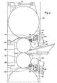
- FIG. 2 of the drawing shows that the device assigned to the upper work roll 55 ′ and the lower work roll 55 ′′ are basically constructed and arranged in the same way.
- the adjustment of the grinding units 59 and 60 or of the grinding unit pairs in the direction of the roller axis takes place via a feed drive 61 which is located together with the pair of grinding units on a cross member 62.
- This cross member 62 is in turn fastened to the guide rings 63 which are rotatably mounted concentrically to the support roller axis in the roller stands or the support roller chocks guided therein.
- control shafts 65 with the support roller and / or work roll chocks are at least vertically displaceable relative to the roll stands and furthermore in their distance from the work roll axes to a predetermined output diameter of the roll bales 55 'and 55 "of the work rolls 52' and 52 "can be tuned.
Landscapes
- Engineering & Computer Science (AREA)
- Mechanical Engineering (AREA)
- Metal Rolling (AREA)
- Reduction Rolling/Reduction Stand/Operation Of Reduction Machine (AREA)
- Control Of Metal Rolling (AREA)
Claims (4)
Priority Applications (1)
| Application Number | Priority Date | Filing Date | Title |
|---|---|---|---|
| AT83107989T ATE16359T1 (de) | 1982-08-23 | 1983-08-12 | Walzgeruest zum auswalzen von bandmaterial unterschiedlicher breite. |
Applications Claiming Priority (2)
| Application Number | Priority Date | Filing Date | Title |
|---|---|---|---|
| DE8223755U DE8223755U1 (de) | 1982-08-23 | 1982-08-23 | Walzgerüst zum Auswalzen von Bandmaterial unterschiedlicher Breite |
| DE8223755U | 1982-08-23 |
Publications (2)
| Publication Number | Publication Date |
|---|---|
| EP0102014A1 EP0102014A1 (fr) | 1984-03-07 |
| EP0102014B1 true EP0102014B1 (fr) | 1985-11-06 |
Family
ID=6742993
Family Applications (1)
| Application Number | Title | Priority Date | Filing Date |
|---|---|---|---|
| EP83107989A Expired EP0102014B1 (fr) | 1982-08-23 | 1983-08-12 | Cage de laminoir pour le laminage de feuillard à largeur différente |
Country Status (5)
| Country | Link |
|---|---|
| US (1) | US4548064A (fr) |
| EP (1) | EP0102014B1 (fr) |
| JP (1) | JPS5954408A (fr) |
| AT (1) | ATE16359T1 (fr) |
| DE (2) | DE8223755U1 (fr) |
Families Citing this family (6)
| Publication number | Priority date | Publication date | Assignee | Title |
|---|---|---|---|---|
| DE3631146A1 (de) * | 1986-09-12 | 1988-03-24 | Kocks Technik | Vorrichtung zur spanabhebenden arbeitsflaechenbearbeitung von walzen |
| EP0300230B1 (fr) * | 1987-07-24 | 1993-02-24 | Daido Tokushuko Kabushiki Kaisha | Remise en état de cylindres de laminoir et appareil pour rectifier ces cylindres |
| DE4105079A1 (de) * | 1990-03-26 | 1991-10-02 | Schloemann Siemag Ag | Schleifvorrichtung zum nachschleifen von walzen eines walzgeruestes waehrend des walzens |
| DE4409300A1 (de) * | 1994-03-18 | 1995-09-21 | Schloemann Siemag Ag | Vorrichtung zum Bearbeiten von Walzen während des Walzvorgangs |
| US5970771A (en) * | 1998-07-10 | 1999-10-26 | Danieli United | Continuous spiral motion system for rolling mills |
| DE102008009902A1 (de) * | 2008-02-19 | 2009-08-27 | Sms Demag Ag | Walzvorrichtung, insbesondere Schubwalzengerüst |
Family Cites Families (8)
| Publication number | Priority date | Publication date | Assignee | Title |
|---|---|---|---|---|
| DE887787C (de) * | 1941-06-13 | 1953-08-27 | Schloemann Ag | Poliervorrichtung fuer die Walzen von Walzwerken |
| US2566679A (en) * | 1943-02-25 | 1951-09-04 | Armzen Company | Rolling mill and lubrication method and means therefor |
| DE1037804B (de) * | 1954-10-01 | 1958-08-28 | E H Oskar Waldrich Dr Ing | Einrichtung an Walzenstuehlen zum Nacharbeiten der Walzen im eingebauten Zustand |
| US3603125A (en) * | 1969-05-20 | 1971-09-07 | Reynolds Metals Co | Automatic control system for means for removing roll coating from a rolling mill work roll without removing the roll from the mill |
| GB1351074A (en) * | 1971-02-15 | 1974-04-24 | Hitachi Ltd | Rolling mills |
| DE2150781A1 (de) * | 1971-10-12 | 1973-04-19 | Schloemann Ag | Anstellvorrichtung fuer eine rotierende walzenbuerste |
| JPS5633106A (en) * | 1979-08-28 | 1981-04-03 | Ishikawajima Harima Heavy Ind Co Ltd | Rolling mill equipped with roll grinder |
| JPS57137011A (en) * | 1981-02-16 | 1982-08-24 | Nippon Kokan Kk <Nkk> | Processing method of mill roll |
-
1982
- 1982-08-23 DE DE8223755U patent/DE8223755U1/de not_active Expired
-
1983
- 1983-08-12 AT AT83107989T patent/ATE16359T1/de not_active IP Right Cessation
- 1983-08-12 DE DE8383107989T patent/DE3361178D1/de not_active Expired
- 1983-08-12 EP EP83107989A patent/EP0102014B1/fr not_active Expired
- 1983-08-19 JP JP58150442A patent/JPS5954408A/ja active Pending
- 1983-08-19 US US06/524,833 patent/US4548064A/en not_active Expired - Fee Related
Also Published As
| Publication number | Publication date |
|---|---|
| DE8223755U1 (de) | 1982-11-18 |
| US4548064A (en) | 1985-10-22 |
| JPS5954408A (ja) | 1984-03-29 |
| EP0102014A1 (fr) | 1984-03-07 |
| DE3361178D1 (en) | 1985-12-12 |
| ATE16359T1 (de) | 1985-11-15 |
Similar Documents
| Publication | Publication Date | Title |
|---|---|---|
| DE3600144A1 (de) | Anordnung zum entfernen von zunder von warmgewalzten stahlbaendern | |
| DE2919105A1 (de) | Walzwerk | |
| EP0620058B1 (fr) | Machine à dressage pour fils | |
| DE102010010758A1 (de) | Spitzenlose Rundschleifmaschine zum Schleifen von stangenförmigen Werkstücken und Verfahren zum spitzenlosen Rundschleifen von stangenförmigen Werkstücken | |
| DE3609290A1 (de) | Schraegwalzwerk | |
| DE69102689T2 (de) | Walzenbiegemaschine. | |
| EP0102014B1 (fr) | Cage de laminoir pour le laminage de feuillard à largeur différente | |
| EP0602492B1 (fr) | Laminoir à plusieurs cylindres | |
| EP0255714B1 (fr) | Laminoir à cylindres multiples avec des cylindres intermédiaires déplaçables axialement et aux extrémités coniques | |
| DE69012949T2 (de) | Walze mit variabler Balligkeit. | |
| EP0689884B1 (fr) | Dresseuse à rouleaux pour le dressage de profilés | |
| EP0665067A1 (fr) | Cage de laminoir à cylindres multiples du type à montants de préférence avec serrage hydraulique direct | |
| EP0086934B1 (fr) | Procédé et cage de laminoir pour laminer des bandes de largeur différente | |
| EP0103667B1 (fr) | Dispositif de guidage à quatre rouleaux pour laminoirs | |
| DE3844162C2 (fr) | ||
| DE68915247T2 (de) | Automatisierbare Rundwalzeneinrichtung mit verzahnten Walzen. | |
| DE2623825B2 (de) | Rippenwalzwerk zum Bearbeiten von Tabakrippen | |
| EP0429815B1 (fr) | Dispositif pour formage d'une bride ou similaire, en particulier à la fin d'un tube métallique à paroi mince | |
| DE2528850B2 (de) | Pilgerschrittwalzwerk zum Rohrkaltwalzen | |
| DE3406313A1 (de) | Walzgeruest | |
| DE966802C (de) | Anlage zum unmittelbaren Auswalzen von im Stranggiessverfahren hergestellten Metallstraengen | |
| DE10328052A1 (de) | Umformwerkzeug, insbesondere Knetwerkzeug | |
| DE3206556A1 (de) | Verfahren und walzgeruest zum auswalzen von bandmaterial unterschiedlicher breite | |
| DE19710060C2 (de) | Vorrichtung zum Richten zylindrischer Werkstücke | |
| EP0204878B1 (fr) | Laminoir en croix |
Legal Events
| Date | Code | Title | Description |
|---|---|---|---|
| PUAI | Public reference made under article 153(3) epc to a published international application that has entered the european phase |
Free format text: ORIGINAL CODE: 0009012 |
|
| 17P | Request for examination filed |
Effective date: 19830819 |
|
| AK | Designated contracting states |
Designated state(s): AT BE DE FR GB IT |
|
| ITF | It: translation for a ep patent filed | ||
| GRAA | (expected) grant |
Free format text: ORIGINAL CODE: 0009210 |
|
| AK | Designated contracting states |
Designated state(s): AT BE DE FR GB IT |
|
| REF | Corresponds to: |
Ref document number: 16359 Country of ref document: AT Date of ref document: 19851115 Kind code of ref document: T |
|
| REF | Corresponds to: |
Ref document number: 3361178 Country of ref document: DE Date of ref document: 19851212 |
|
| ET | Fr: translation filed | ||
| PGFP | Annual fee paid to national office [announced via postgrant information from national office to epo] |
Ref country code: AT Payment date: 19860812 Year of fee payment: 4 |
|
| PLBE | No opposition filed within time limit |
Free format text: ORIGINAL CODE: 0009261 |
|
| STAA | Information on the status of an ep patent application or granted ep patent |
Free format text: STATUS: NO OPPOSITION FILED WITHIN TIME LIMIT |
|
| 26N | No opposition filed | ||
| PG25 | Lapsed in a contracting state [announced via postgrant information from national office to epo] |
Ref country code: AT Effective date: 19870812 |
|
| BERE | Be: lapsed |
Owner name: SMS SCHLOEMANN-SIEMAG A.G. Effective date: 19870831 |
|
| PG25 | Lapsed in a contracting state [announced via postgrant information from national office to epo] |
Ref country code: FR Free format text: LAPSE BECAUSE OF NON-PAYMENT OF DUE FEES Effective date: 19880429 |
|
| PG25 | Lapsed in a contracting state [announced via postgrant information from national office to epo] |
Ref country code: DE Effective date: 19880503 |
|
| GBPC | Gb: european patent ceased through non-payment of renewal fee | ||
| REG | Reference to a national code |
Ref country code: FR Ref legal event code: ST |
|
| PG25 | Lapsed in a contracting state [announced via postgrant information from national office to epo] |
Ref country code: GB Free format text: LAPSE BECAUSE OF NON-PAYMENT OF DUE FEES Effective date: 19881122 |
|
| PG25 | Lapsed in a contracting state [announced via postgrant information from national office to epo] |
Ref country code: BE Effective date: 19890831 |