EP0102942A2 - Zweiradfahrzeug - Google Patents
Zweiradfahrzeug Download PDFInfo
- Publication number
- EP0102942A2 EP0102942A2 EP83890147A EP83890147A EP0102942A2 EP 0102942 A2 EP0102942 A2 EP 0102942A2 EP 83890147 A EP83890147 A EP 83890147A EP 83890147 A EP83890147 A EP 83890147A EP 0102942 A2 EP0102942 A2 EP 0102942A2
- Authority
- EP
- European Patent Office
- Prior art keywords
- frame
- unit
- mating surface
- rear wheel
- structural unit
- Prior art date
- Legal status (The legal status is an assumption and is not a legal conclusion. Google has not performed a legal analysis and makes no representation as to the accuracy of the status listed.)
- Granted
Links
Images


Classifications
-
- B—PERFORMING OPERATIONS; TRANSPORTING
- B62—LAND VEHICLES FOR TRAVELLING OTHERWISE THAN ON RAILS
- B62K—CYCLES; CYCLE FRAMES; CYCLE STEERING DEVICES; RIDER-OPERATED TERMINAL CONTROLS SPECIALLY ADAPTED FOR CYCLES; CYCLE AXLE SUSPENSIONS; CYCLE SIDECARS, FORECARS, OR THE LIKE
- B62K11/00—Motorcycles, engine-assisted cycles or motor scooters with one or two wheels
- B62K11/02—Frames
-
- B—PERFORMING OPERATIONS; TRANSPORTING
- B62—LAND VEHICLES FOR TRAVELLING OTHERWISE THAN ON RAILS
- B62K—CYCLES; CYCLE FRAMES; CYCLE STEERING DEVICES; RIDER-OPERATED TERMINAL CONTROLS SPECIALLY ADAPTED FOR CYCLES; CYCLE AXLE SUSPENSIONS; CYCLE SIDECARS, FORECARS, OR THE LIKE
- B62K19/00—Cycle frames
- B62K19/30—Frame parts shaped to receive other cycle parts or accessories
- B62K19/34—Bottom brackets
Definitions
- the invention relates to a two-wheeled vehicle with a frame which has a frame support leading obliquely downwards from the steering head and an upward-facing frame support which adjoins the seat post and connects to the seat post at the bottom, the frame having an underside fitting surface in the apex region of the two frame supports, to which one the bearing of a pedal crank and the unit comprising the rear wheel fork can be connected.
- a known two-wheeled vehicle namely a bicycle (DE-C-19 61 989)
- the two frame supports are combined to form an approximately V-shaped or U-shaped tube.
- On this tube in the apex area are welded two bushes directed transversely to the tube axis, which take up the screws for fastening a housing which is made of sheet metal and ends in two arms forming the rear wheel fork.
- This bicycle training is intended to enable dismantling, but is not suitable for producing two-wheel vehicles of different types with the same frame.
- a cast V-shaped bicycle frame made of light metal is already known (DE-C-907 260 and DE-C-10 34 999), which has a fastening flange which projects beyond its width in the apex region of the two frame supports and has a fitting surface on its underside Motor gear block is present, which is attached to this by means of screws inserted into the mounting flange from above.
- the considerable increase in the width of the frame through the mounting flange is extremely unfavorable for a bicycle, especially since every widening of the frame is also associated with an increase in weight.
- the known frame does not offer the possibility of using it unchanged for a bicycle with a rigid rear fork or a bicycle with a sprung rear swing arm.
- the invention is therefore based on the object of improving the two-wheeled vehicle described at the outset such that a bicycle with a rigid rear wheel fork or a bicycle with a sprung rear wheel swing arm can be produced while maintaining the frame and without changing it.
- the frame has blind holes within the mating surface that extends only over the frame width in the apex region and the unit by means of screws and dowel pins inserted into the blind bores from below either directly or with the interposition of one with a pivot bearing for the unit as well an abutment for a support spring provided base plate can be attached to the frame, the structural unit possibly forming the load-bearing part of a closed chain case.
- a rubber spring, but also a plate spring assembly can be arranged as a support spring, the latter having the advantage that the spring strength can be influenced by changing the number of single-plate springs.
- a particularly light sports vehicle or a comfortable touring vehicle can be achieved.
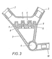
- the two-wheeled vehicle has a frame which comprises a frame support 2 which leads obliquely downwards from a steering head 1 and an upward-directed frame support 3 which adjoins this at the bottom and accommodates a seat post (not shown).
- the frame In the apex area of the two frame supports 2, 3, that is to say in the area of section 4, the frame has a mating surface 4 on the underside.
- the mating surface 5 a bearing 6 for a pedal crank housing 7 fastened with screws 8 and 9 dowel pins.
- This housing 7 forms a rigid structural unit with a rear wheel fork 10, the rear wheel fork 10 being supported at the top of the vehicle frame by oblique struts 11.
- the struts 11 are simply inserted into pocket openings in the frame.
- the housing 7 forms the load-bearing part of a closed chain case 12, the space between the bearing 6 of the pedal crank and the housing wall adjoining the mating surface being closed off by a side cover 13.
- the mating surface 5 carries a base plate 14 which is provided with a pivot bearing 15 for the housing 7a and an abutment for a rubber support spring 17.
- the housing 7a also forms the supporting part of the closed chain case 12. The space between the housing 7a and the mating surface 5 is covered by a bellows 18.
- the rear wheel swing arm consisting of the housing 7a and the chain case 12 could also be designed as a motor-gear housing, so that a motor bike results.
Landscapes
- Engineering & Computer Science (AREA)
- Mechanical Engineering (AREA)
- Motorcycle And Bicycle Frame (AREA)
- Axle Suspensions And Sidecars For Cycles (AREA)
- Automatic Cycles, And Cycles In General (AREA)
Abstract
Description
- Die Erfindung bezieht sich auf ein Zweiradfahrzeug mit einem Rahmen, der einen vom Lenkkopf schräg abwärts führenden Rahmenträger und einen an diesen unten anschliessenden, aufwärtsgerichteten, die Sattelstütze aufnehmenden Rahmenträger aufweist, wobei der Rahmen im Scheitelbereich der beiden Rahmenträger eine unterseitige Paßfläche besitzt, an die eine das Lager einer Tretkurbel und die Hinterradgabel umfassende Baueinheit anschließbar ist.
- Bei einem bekannten Zweiradfahrzeug, nämlich einem Fahrrad (DE-C-19 61 989) sind die beiden Rahmenträger zu einem etwa V- oder U-förmig gebogenen Rohr vereint. An diesem Rohr sind im Scheitelbereich zwei quer zur Rohrachse gerichtete Buchsen angeschweißt, die Schrauben zur Befestigung eines Gehäuses aufnehmen, das aus Blech besteht und in zwei die Hinterradgabel bildende Arme ausläuft. Diese Fahrradausbildung soll die Zerlegbarkeit ermöglichen, ist aber nicht dazu geeignet, Zweiradfahrzeuge verschiedenen Typs mit dem gleichen Rahmen herzustellen. Es ist auch schon ein gegossener V-förmiger Fahrradrahmen aus Leichtmetall bekannt (DE-C-907 260 bzw. DE-C-10 34 999), der im Scheitelbereich der beiden Rahmenträger einen über seine Breite hinausragenden Befestigungsflansch besitzt, an dessen unterseitiger Paßfläche ein Motorgetriebeblock anliegt, der mittels von oben in den Befestigungsflansch eingeführter Schrauben an diesem befestigt ist. Die beträchtliche Vergrößerung der Rahmenbreite durch den Befestigungsflansch ist bei einem Fahrrad äußerst ungünstig, zumal jede Verbreiterung des Rahmens auch mit einer Gewichtsvermehrung verbunden ist. Der bekannte Rahmen bietet nicht die Möglichkeit, ihn unverändert für ein Fahrrad mit starrer Hinterradgabel oder ein Fahrrad mit abgefederter Hinterradschwinge zu verwenden.
- Der Erfindung liegt daher die Aufgabe zugrunde, das eingangs geschilderte Zweiradfahrzeug so zu verbessern, daß unter Beibehaltung des Rahmens und ohne dessen Abänderung wahlweise ein Fahrrad mit starrer Hinterradgabel oder ein Fahrrad mit abgefederter Hinterradschwinge hergestellt werden kann.
- Die Erfindung löst die gestellte Aufgabe dadurch, daß der Rahmen innerhalb der sich lediglich über die Rahmenbreite im Scheitelbereich erstreckenden Paßfläche Sackbohrungen aufweist und die Baueinheit mittels von unten in die Sackbohrungen eingeführter Schrauben und Paßstifte entweder unmittelbar oder unter Zwischenlage einer mit einem Schwenklager für die Baueinheit sowie einem Widerlager für eine Stützfeder versehenen Grundplatte am Rahmen befestigbar ist, wobei die Baueinheit gegebenenfalls den tragenden Teil eines geschlossenen Kettenkastens bildet.
- Wird die mit der Hinterradgabel starre Baueinheit, die auch das Lager für die Tretkurbel umfaßt, unmittelbar an der Paßfläche befestigt, so ergibt sich ein übliches Fahrrad mit ungefedertem Hinterrad und ohne seitlich-vom Rahmen abstehende Befestigungsteile, wobei die Hinterradgabel auch durch Schrägstreben am Rahmen abgestützt sein kann. Zur Aufnahme der oberen Strebenenden genügen Sacköffnungen im Rahmen, so daß keine weiteren Maßnahmen getroffen zu werden brauchen und die Montage der Baueinheit keinerlei Schwierigkeiten bereitet. Soll ein Zweiradfahrzeug mit Hinterradschwinge hergestellt werden, so ist es lediglich notwendig, an der Paßfläche die Grundplatte anzubringen, die dann.nicht nur das Schwenklager für die mit der Hinterradgabel vereinigte Baueinheit bildet, sondern zugleich auch das Widerlager für die zwischen der Baueinheit und der Grundplatte eingesetzte Stützfeder aufweist, so daß sich die gewünschte gefederte Hinterradschwinge ergibt,.ohne am Rahmen Veränderungen vornehmen oder Federwiderlager vorsehen zu müssen. Als Stützfeder kann eine Gummifeder, aber auch ein Tellerfederpaket angeordnet werden, welch letzteres den Vorteil hat, daß sich durch Veränderung der Anzahl der Einzeltellerfedern die Federstärke beeinflussen läßt. Je nachdem, ob die Baueinheit zu einem geschlossenen Kettenkasten ergänzt wird oder nicht, kann entweder ein besonders leichtes Sportfahrzeug oder ein komfortables Tourenfahrzeug erreicht werden.
- Um eine Verschmutzung des Schwenklagers für die Baueinheit sowie der Stützfeder zu verhinden und das Erscheinungsbild zu verbessern, ist bei Anordnung der Grundplatte der Raum zwischen dem Gehäuse =der Baueinheit und der Paßfläche durch einen Faltenbalg abgedeckt.
- In der Zeichnung ist der Erfindungsgegenstand beispielsweise dargestellt, und zwar zeigen
- Fig. 1 den Rahmen eines Fahrrades mit starrer Hinterradgabel in Seitenansicht,
- Fig. 2 den gleichen Rahmen bei Verwendung mit einer Hinterradschwinge in Ansicht von der anderen Seite,
- Fig. 3 die Befestigung einer starren Hinterradgabel am Fahrzeugrahmen im größeren Maßstab im Vertikalschnitt nach der Linie III-III der Fig. 5,
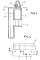
- Fig. 4 einen zugehörigen Querschnitt im Bereich der Tretlagerachse,
- Fig. 5 einen Schnitt entlang der Paßfläche nach der Linie V-V der Fig. 4 und
- Fig. 6 die Anordnung einer Hinterradschwinge in einer etwa der Fig. 3 entsprechenden Darstellungsweise.
- Das erfindungsgemäße Zweiradfahrzeug weist einen Rahmen auf, der einen von einem Lenkkopf 1 schräg abwärts führenden Rahmenträger 2 und einen an diesen unten anschliessenden aufwärts gerichteten, eine nicht dargestellte Sattelstütze aufnehmenden Rahmenträger 3 umfaßt. Im Scheitelbereich der beiden Rahmenträger 2, 3, also im Bereich des Abschnittes 4, besitzt der Rahmen eine unterseitige Paßfläche 4. Gemäß den Fig. 1 und 3 bis 5 ist unmittelbar an der Paßfläche 5 ein ein Lager 6 für eine Tretkurbel umfassendes Gehäuse 7 mit Hilfe von Schrauben 8 und Paßstiften 9 befestigt. Dieses Gehäuse 7 bildet mit einer Hinterradgabel 10 eine starre Baueinheit, wobei die Hinterradgabel 10 durch Schrägstreben 11 oben am Fahrzeugrahmen abgestützt ist. Die Streben 11 sind einfach in Sacköffnungen des Rahmens eingesteckt.
- Gemäß Fig. 4 und 5 bildet das Gehäuse 7 den tragenden Teil eines geschlossenen Kettenkastens 12, wobei der Raum zwischen dem Lager 6 der Tretkurbel und der an die Paßfläche anschließenden Gehäosewand durch einen Seitendeckel 13 abgeschlossen sind.
- Die Fig. 2 und 6 zeigen eine Variante, bei der die Paßfläche 5 eine Grundplatte 14 trägt, die mit einem Schwenklager 15 für das Gehäuse 7a und einem Widerlager für eine Gummistützfeder 17 versehen ist. Das Gehäuse 7a bildet ebenfalls den tragenden Teil des geschlossenen Kettenkastens 12. Der Raum zwischen dem Gehäuse 7a und der Paßfläche 5 ist durch einen Faltenbalg 18 abgedeckt.
- Die aus dem Gehäuse 7a und dem Kettenkasten 12 bestehende Hinterradschwinge könnte auch als Motor-Getriebegehäuse ausgebildet sein, so daß sich ein Motorfahrrad ergibt.
Claims (2)
Applications Claiming Priority (2)
| Application Number | Priority Date | Filing Date | Title |
|---|---|---|---|
| AT0335182A AT375613B (de) | 1982-09-08 | 1982-09-08 | Zweiradfahrzeug |
| AT3351/82 | 1982-09-08 |
Publications (3)
| Publication Number | Publication Date |
|---|---|
| EP0102942A2 true EP0102942A2 (de) | 1984-03-14 |
| EP0102942A3 EP0102942A3 (en) | 1985-07-31 |
| EP0102942B1 EP0102942B1 (de) | 1987-08-19 |
Family
ID=3549207
Family Applications (1)
| Application Number | Title | Priority Date | Filing Date |
|---|---|---|---|
| EP83890147A Expired EP0102942B1 (de) | 1982-09-08 | 1983-09-06 | Zweiradfahrzeug |
Country Status (5)
| Country | Link |
|---|---|
| US (1) | US4529216A (de) |
| EP (1) | EP0102942B1 (de) |
| JP (1) | JPS5967184A (de) |
| AT (1) | AT375613B (de) |
| DE (1) | DE3373079D1 (de) |
Cited By (1)
| Publication number | Priority date | Publication date | Assignee | Title |
|---|---|---|---|---|
| WO2013117643A1 (de) | 2012-02-09 | 2013-08-15 | Velobility Ag | Antriebsvorrichtung für Fahrräder |
Families Citing this family (12)
| Publication number | Priority date | Publication date | Assignee | Title |
|---|---|---|---|---|
| JPH0674072B2 (ja) * | 1986-05-12 | 1994-09-21 | ジェイ トリンブル,ブレント | 複合自転車フレームおよびその製造方法 |
| US4986949A (en) * | 1986-05-12 | 1991-01-22 | Trimble Brent J | Method of making composite bicycle frames |
| US4902458A (en) * | 1987-05-12 | 1990-02-20 | Trimble Brent J | Method of molding composite bicycle frames |
| US4889355A (en) * | 1987-11-20 | 1989-12-26 | Trimble Brent J | Composite bicycle frames and methods of making same |
| US4828781A (en) * | 1987-06-26 | 1989-05-09 | Duplessis Delano A | Method of molding composite bicycle frames |
| US4923203A (en) * | 1987-12-23 | 1990-05-08 | Trimble Brent J | Composite bicycle frame with crossed tubular portions |
| GB2284185A (en) * | 1993-11-30 | 1995-05-31 | Bruce Cameron Lee | Bicycle rear suspension |
| DE19744118A1 (de) * | 1997-10-06 | 1999-04-08 | Matthias Frerck | Tretkurbeleinheit für Fahrräder oder dergleichen in Tauschkassette |
| ITUD990173A1 (it) * | 1999-09-23 | 2001-03-23 | Facchini Edoardo Progettazioni | Bicicletta |
| JP4303544B2 (ja) * | 2003-09-09 | 2009-07-29 | 本田技研工業株式会社 | 小型車両のフレーム構造 |
| DE102018116408B4 (de) * | 2018-07-06 | 2022-08-25 | Pierer E-Bikes Deutschland Gmbh | Fahrradrahmen mit einer Antriebsaufnahme |
| JP7495324B2 (ja) * | 2020-10-02 | 2024-06-04 | ジヤトコ株式会社 | 自転車及び自転車の非電動化ユニット |
Family Cites Families (9)
| Publication number | Priority date | Publication date | Assignee | Title |
|---|---|---|---|---|
| US500177A (en) * | 1893-06-27 | Bicycle-frame | ||
| GB118453A (en) * | 1917-08-29 | 1918-08-29 | Lancelot Steele Parker | Improvements in and relating to the Construction of Motor Cycle or the like Frames. |
| GB517604A (en) * | 1938-08-11 | 1940-02-02 | Ernest Edwin Wallington Butt | Improvements in the frames of motor-propelled cycles |
| DE880712C (de) * | 1951-09-27 | 1953-06-25 | Hermann Dr-Ing Klaue | Gegossener Fahrradrahmen aus Leichtmetall |
| DE903180C (de) * | 1952-01-08 | 1954-02-01 | Klaue Hermann | Gegossener Fahrradrahmen aus Leichtmetall |
| DE1034999B (de) * | 1952-02-19 | 1958-07-24 | Klaue Hermann | Aus zwei gepressten Halbschalen zusammengesetzter, aus Leichtmetallblech gefertigter hohler Rahmen fuer Einspurfahrzeuge |
| FR1147096A (fr) * | 1955-02-23 | 1957-11-19 | Halleiner Motorenwerke Hinterb | Cadre de motocyclette ou de vélomoteur |
| US3615104A (en) * | 1968-12-11 | 1971-10-26 | Matsushita Electric Industrial Co Ltd | Collapsible bicycle |
| US4139072A (en) * | 1974-11-21 | 1979-02-13 | Anthony Dawson | Motorcycle formed of detachable frame members |
-
1982
- 1982-09-08 AT AT0335182A patent/AT375613B/de not_active IP Right Cessation
-
1983
- 1983-08-25 US US06/526,393 patent/US4529216A/en not_active Expired - Fee Related
- 1983-09-06 DE DE8383890147T patent/DE3373079D1/de not_active Expired
- 1983-09-06 EP EP83890147A patent/EP0102942B1/de not_active Expired
- 1983-09-07 JP JP58163420A patent/JPS5967184A/ja active Pending
Cited By (1)
| Publication number | Priority date | Publication date | Assignee | Title |
|---|---|---|---|---|
| WO2013117643A1 (de) | 2012-02-09 | 2013-08-15 | Velobility Ag | Antriebsvorrichtung für Fahrräder |
Also Published As
| Publication number | Publication date |
|---|---|
| EP0102942B1 (de) | 1987-08-19 |
| JPS5967184A (ja) | 1984-04-16 |
| ATA335182A (de) | 1984-01-15 |
| EP0102942A3 (en) | 1985-07-31 |
| DE3373079D1 (en) | 1987-09-24 |
| US4529216A (en) | 1985-07-16 |
| AT375613B (de) | 1984-08-27 |
Similar Documents
| Publication | Publication Date | Title |
|---|---|---|
| DE4204825C2 (de) | Wagenkasten für Kraftfahrzeuge, insbesondere Personenkraftwagen | |
| EP1924486B1 (de) | Vorderachsträger, insbesondere für kraftfahrzeuge | |
| DE19848602B4 (de) | Durch Kraftantrieb unterstütztes Fahrrad | |
| DE10013931B4 (de) | Rahmenstruktur eines Kraftrads | |
| EP0102942B1 (de) | Zweiradfahrzeug | |
| DE69800977T2 (de) | Gelenkstütze für Motorradwindlaufkonstruktion | |
| EP0561837A1 (de) | Tragstruktur einer karosserie eines personenkraftwagens. | |
| DE102004042322B4 (de) | Hintere Schutzvorrichtung und dazugehörige Lagerstruktur für ein Motorrad, und Motorrad, welches diese aufweist | |
| EP0561804B1 (de) | Federbeinaufnahme einer fahrzeugkarosserie | |
| EP0940320B1 (de) | Fahrgestell eines schweren Nutzfahrzeuges | |
| EP4242091A1 (de) | Fahrradrahmen mit anschluss für einen mittelständer, und fahrradständer | |
| DE3220689A1 (de) | Starrachsaufhaengung fuer kraftfahrzeuge | |
| DE2514456C3 (de) | Achsschenkelträger für Kraftfahrzeuge | |
| DE4212313A1 (de) | Federnde Achsaufhängung für Kraftfahrzeuge mit Feder, Stabilisator und Stoßdämpfer | |
| DE2900106C3 (de) | Federung für Motorräder o.dgl. | |
| DE4217058A1 (de) | Fahrradrahmen mit Hinterradfederung | |
| DE3540976A1 (de) | Dreiraedriges tretpedalfahrzeug | |
| DE1930802C3 (de) | Radaufhängung für die Hinterräder eines Kraftfahrzeuges | |
| WO1997016339A1 (de) | Umbausatz für einen zweiradroller | |
| DE60102688T2 (de) | Motorrad | |
| DE1505227A1 (de) | Fahrrad,motorisiertes Fahrrad oder Moped | |
| AT201439B (de) | Radbefestigungsaggregat | |
| DE10240872B4 (de) | Kraftrad | |
| DE341559C (de) | Vorrichtung zur Abfederung von Fahrraedern | |
| DE2913739A1 (de) | Fahrrad-rahmen |
Legal Events
| Date | Code | Title | Description |
|---|---|---|---|
| PUAI | Public reference made under article 153(3) epc to a published international application that has entered the european phase |
Free format text: ORIGINAL CODE: 0009012 |
|
| AK | Designated contracting states |
Designated state(s): BE CH DE FR GB IT LI LU NL SE |
|
| PUAL | Search report despatched |
Free format text: ORIGINAL CODE: 0009013 |
|
| AK | Designated contracting states |
Designated state(s): BE CH DE FR GB IT LI LU NL SE |
|
| 17P | Request for examination filed |
Effective date: 19850917 |
|
| 17Q | First examination report despatched |
Effective date: 19860717 |
|
| GRAA | (expected) grant |
Free format text: ORIGINAL CODE: 0009210 |
|
| AK | Designated contracting states |
Kind code of ref document: B1 Designated state(s): BE CH DE FR GB IT LI LU NL SE |
|
| REF | Corresponds to: |
Ref document number: 3373079 Country of ref document: DE Date of ref document: 19870924 |
|
| ITF | It: translation for a ep patent filed | ||
| PG25 | Lapsed in a contracting state [announced via postgrant information from national office to epo] |
Ref country code: LU Free format text: LAPSE BECAUSE OF NON-PAYMENT OF DUE FEES Effective date: 19870930 |
|
| PGFP | Annual fee paid to national office [announced via postgrant information from national office to epo] |
Ref country code: NL Payment date: 19870930 Year of fee payment: 5 |
|
| ET | Fr: translation filed | ||
| PLBE | No opposition filed within time limit |
Free format text: ORIGINAL CODE: 0009261 |
|
| STAA | Information on the status of an ep patent application or granted ep patent |
Free format text: STATUS: NO OPPOSITION FILED WITHIN TIME LIMIT |
|
| 26N | No opposition filed | ||
| PG25 | Lapsed in a contracting state [announced via postgrant information from national office to epo] |
Ref country code: GB Effective date: 19880906 |
|
| PG25 | Lapsed in a contracting state [announced via postgrant information from national office to epo] |
Ref country code: SE Effective date: 19880907 |
|
| PG25 | Lapsed in a contracting state [announced via postgrant information from national office to epo] |
Ref country code: LI Effective date: 19880930 Ref country code: CH Effective date: 19880930 Ref country code: BE Effective date: 19880930 |
|
| BERE | Be: lapsed |
Owner name: STEYR-DAIMLER-PUCH A.G. Effective date: 19880930 |
|
| PG25 | Lapsed in a contracting state [announced via postgrant information from national office to epo] |
Ref country code: NL Effective date: 19890401 |
|
| NLV4 | Nl: lapsed or anulled due to non-payment of the annual fee | ||
| PG25 | Lapsed in a contracting state [announced via postgrant information from national office to epo] |
Ref country code: FR Free format text: LAPSE BECAUSE OF NON-PAYMENT OF DUE FEES Effective date: 19890531 |
|
| REG | Reference to a national code |
Ref country code: CH Ref legal event code: PL |
|
| GBPC | Gb: european patent ceased through non-payment of renewal fee | ||
| PG25 | Lapsed in a contracting state [announced via postgrant information from national office to epo] |
Ref country code: DE Effective date: 19890601 |
|
| REG | Reference to a national code |
Ref country code: FR Ref legal event code: ST |
|
| EUG | Se: european patent has lapsed |
Ref document number: 83890147.8 Effective date: 19890712 |