EP0103042B1 - Ventilator mit zur Vermeidung unerwünschter Drehzahlen selbsttätig um eine Längsachse verdrehbaren Flügeln - Google Patents
Ventilator mit zur Vermeidung unerwünschter Drehzahlen selbsttätig um eine Längsachse verdrehbaren Flügeln Download PDFInfo
- Publication number
- EP0103042B1 EP0103042B1 EP82108470A EP82108470A EP0103042B1 EP 0103042 B1 EP0103042 B1 EP 0103042B1 EP 82108470 A EP82108470 A EP 82108470A EP 82108470 A EP82108470 A EP 82108470A EP 0103042 B1 EP0103042 B1 EP 0103042B1
- Authority
- EP
- European Patent Office
- Prior art keywords
- blades
- fan
- impeller hub
- stop means
- remaining
- Prior art date
- Legal status (The legal status is an assumption and is not a legal conclusion. Google has not performed a legal analysis and makes no representation as to the accuracy of the status listed.)
- Expired
Links
- 230000007257 malfunction Effects 0.000 claims abstract description 6
- 230000005484 gravity Effects 0.000 claims abstract description 5
- 238000011144 upstream manufacturing Methods 0.000 claims abstract description 5
- 238000004880 explosion Methods 0.000 description 4
- 230000007704 transition Effects 0.000 description 2
- 230000005540 biological transmission Effects 0.000 description 1
- 238000010276 construction Methods 0.000 description 1
- 238000001816 cooling Methods 0.000 description 1
- 230000001419 dependent effect Effects 0.000 description 1
- 230000000694 effects Effects 0.000 description 1
- 230000003993 interaction Effects 0.000 description 1
- 230000002093 peripheral effect Effects 0.000 description 1
Images

Classifications
-
- F—MECHANICAL ENGINEERING; LIGHTING; HEATING; WEAPONS; BLASTING
- F04—POSITIVE - DISPLACEMENT MACHINES FOR LIQUIDS; PUMPS FOR LIQUIDS OR ELASTIC FLUIDS
- F04D—NON-POSITIVE-DISPLACEMENT PUMPS
- F04D29/00—Details, component parts, or accessories
- F04D29/26—Rotors specially for elastic fluids
- F04D29/32—Rotors specially for elastic fluids for axial flow pumps
- F04D29/34—Blade mountings
- F04D29/36—Blade mountings adjustable
- F04D29/362—Blade mountings adjustable during rotation
- F04D29/366—Adjustment by interaction of inertion and lift
-
- F—MECHANICAL ENGINEERING; LIGHTING; HEATING; WEAPONS; BLASTING
- F04—POSITIVE - DISPLACEMENT MACHINES FOR LIQUIDS; PUMPS FOR LIQUIDS OR ELASTIC FLUIDS
- F04D—NON-POSITIVE-DISPLACEMENT PUMPS
- F04D27/00—Control, e.g. regulation, of pumps, pumping installations or pumping systems specially adapted for elastic fluids
- F04D27/002—Control, e.g. regulation, of pumps, pumping installations or pumping systems specially adapted for elastic fluids by varying geometry within the pumps, e.g. by adjusting vanes
Definitions
- the invention relates to a fan with blades which can be rotated automatically about a longitudinal axis in order to avoid undesired rotational speeds according to the preamble of patent claim 1 and of patent claim 3; such a fan is known from DE-A-862 280 and FR-A-1 553 046.
- the blades of the variable-pitch propeller are adjusted in a speed-dependent manner by centrifugal force regulators in order to achieve a starting position in a particularly simple manner in such a way that they are brought to a steeper position and thus a smaller angle with respect to the wind direction when the vehicle is at a standstill and at very low speeds will.
- the centrifugal forces work on the respective wing axis via transmission means.
- the centrifugal force device is to be used both for the adjustment in the start-up area and in the work area.
- the known device is considered particularly advantageous for the use of wind power motors for small systems, since the propeller can start with large moments on the one hand and, on the other hand, as a high-speed runner in the actual working area of the impeller, it can be adjusted automatically as a function of speed in such a way that a control to an approximately constant speed or results in consistent performance.
- the aim is to ensure that a generator connected to a wind turbine is no longer supplied with additional energy from a certain wind speed.
- the wind turbines which operate continuously in turbine operation, they are first pulled against a stop with a spring; depending on the wind speed and in particular on the setting or the force of the spring, the wing lifts off the stop during operation, so that the aerodynamic angle of attack increases.
- a weight arranged downstream on the wing is provided in order to reduce the angle of attack due to special inertia effects when the wind turbine accelerates.
- the object of the present invention is to protect the fan from a harmful increase in speed in the event of a malfunction in the event of an external pressure wave driving the fan while maintaining its direction of rotation according to the principle of a wind turbine by the flow forces occurring in the pressure wave.
- a fault is to be considered in particular when the secured secondary cooling circuit of a power plant block, consisting of cell coolers with a fan, must also be designed against the "external explosion" load case.
- the explosion pressure wave is idealized by a pressure-time function, which among other things is characterized by a short but very high pressure increase or speed increase at the beginning of the start of the pressure wave. If the safety design of the fan provided in accordance with the task were not present, the pressure wave that would start would cause the operating speed of the fan to rise to such a peak speed that even materials with a large tear length could not withstand this load.
- the counterweights in cooperation with the blades adjustable about their special longitudinal axes and the acting air and centrifugal forces ensure that the adjustable blades on the one hand in normal operation in accordance with the teaching of claim 1
- Design provided by the centrifugal force is not rotated in the closed position with the wing chord running almost perpendicular to the fan axis, but pressed against the first stop or, in the case of the design provided for in claim 3, is pressed against the first stop with moderate force that can be overcome in the event of a fault, and on the other hand
- the triggering criterion of the reversal of the resulting air force characteristic of the transition from pump to turbine operation, tilts from its first operating position into the second malfunctioning position and, in this, an undesirable rotation increase avoiding position can be held either by the second stop or in the zero-lift equilibrium position without a separate stop.
- every second wing 2 is alternately designed as an independently rotatable wing 3, while the remaining wings 2 are arranged fixedly on the circumference of the impeller hub 1.
- 4 shows, in a partial section, a top view of a developed impeller hub 1, two vanes 2 fixedly arranged on the circumference of this impeller hub and two vanes 3, each of which rotates along its longitudinal axis 31.
- the rotatable vanes 3 are entered in FIG. in which they abut against stops 7 with their upstream ends.
- the rotatable wings 3 are pivoted about their longitudinal axis 31 in such a way that their downstream ends rest against stops 6 and one to the fixed wings 2 take up the equivalent wing position.
- the centrifugal weights fixedly arranged on the rotatable wings 3 according to the invention are not shown in FIG. 4.
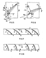
- FIG. 1 shows a sectional view of a single wing 3, which in the normal operating position due to the assumed direction of rotation: n or flow direction: L of the air, the bearing in the axis of gravity 31 and the counterweight 5 shown with its outflow end against the first Stop 6 is pressed.
- the counterweights 5 compensate for the influence of the centrifugal forces, which otherwise try to turn the rotatable blades in the closed position (wing chord perpendicular to the impeller axis) and, on the other hand, achieve that the rotating blades with a definable pressure against the stop also when starting the impeller 6 are pressed.
- the counterweights are each arranged in the quadrant of an assumed coordinate system, the coordinate origin of which according to FIG. 1 lies in the center of gravity of the longitudinal axis 31 and the abscissa x in the directions of rotation of the impeller or the ordinate y thereof in the direction L of the air flow.
- Fig. 1 the resulting air force F, which acts on the vane 3 in normal fan operation, is also entered, which is due to the entered speed triangle with the assumed speeds: passage speed c m circumferential speed u and the relative or inflow speed w (neglecting the behind Impeller existing swirl component) results in the wing-fixed coordinate system.
- FIGS. 5 to 8 show a further embodiment of a pressure-resistant axial fan designed according to the invention with the direction of rotation again assumed: n and the direction of flow: L of the air.
- all vanes 4 arranged on the circumference of the impeller hub 1 are rotatably mounted. The rotation takes place about a longitudinal axis 41 in the first quarter of the wing depth.
- Each wing is in turn firmly connected to a counterweight 5 arranged in the upstream region of the impeller hub 1 according to FIGS. 5 and 6.
- the counterweights 5 are not shown in the schematic development of the impeller hub 1 according to FIG. 7 or FIG. 8.
- each blade 4 is in normal fan operation due to the interaction of the air and centrifugal forces at its output end in the start-up or Operating position pressed against a first stop ⁇ .
- Each individual wing will adjust in the intended bearing in the direction of zero lift if the air force F 2 changes its sign after the impact of the pressure wave and acts on the wing according to FIG. 6.
- the air force causes each wing to bear against its stop 8.
- the undesired adjusting torque acting on the wing during operation due to centrifugal forces is in turn compensated by counterweights 5.
- the counterweight is in turn arranged in quadrant 111 of an assumed coordinate system, the coordinate origin of which lies at the point of the longitudinal axis 41 and the abscissa x in the direction of rotation n and the ordinate thereof in the direction of the air flow.
- the counterweight 5 is dimensioned in the sense of the invention so that, on the one hand, in normal operation, in particular in start-up operation, a wing system with a defined pressure on the stop 8 is ensured and, in the event of a malfunction, the relatively low air force can tip the wing into the zero lift position.
- Fig. 7 shows in a partial development of the impeller hub 1, the operating position of the vanes 4 with the assumed assumed direction of rotation n of the impeller and the inflow direction L of the pressure wave.
- 8 shows the same development of the impeller hub, however, with vanes 4 rotated about their respective longitudinal axis 41 in the zero lift direction and with neglected bearing friction in each case.
Landscapes
- Engineering & Computer Science (AREA)
- Mechanical Engineering (AREA)
- General Engineering & Computer Science (AREA)
- Physics & Mathematics (AREA)
- Geometry (AREA)
- Structures Of Non-Positive Displacement Pumps (AREA)
- Air-Conditioning For Vehicles (AREA)
- Air-Flow Control Members (AREA)
- Control Of Positive-Displacement Air Blowers (AREA)
Priority Applications (5)
| Application Number | Priority Date | Filing Date | Title |
|---|---|---|---|
| DE8282108470T DE3272588D1 (en) | 1982-09-14 | 1982-09-14 | Fan comprising automatically adjustable blades about its longitudinal axis to avoid undesirable rotational speed |
| EP82108470A EP0103042B1 (de) | 1982-09-14 | 1982-09-14 | Ventilator mit zur Vermeidung unerwünschter Drehzahlen selbsttätig um eine Längsachse verdrehbaren Flügeln |
| AT82108470T ATE21438T1 (de) | 1982-09-14 | 1982-09-14 | Ventilator mit zur vermeidung unerwuenschter drehzahlen selbsttaetig um eine laengsachse verdrehbaren fluegeln. |
| DD83254745A DD217585A5 (de) | 1982-09-14 | 1983-09-12 | Ventilator mit zur vermeidung unerwuenschter drehzahlen selbsttaetig um eine laengsachse verdrehbaren fluegeln |
| DK413983A DK157147C (da) | 1982-09-14 | 1983-09-13 | Ventilator med vinger, der er svingelige om deres laengdeakser til undgaaelse af uoenskede omdrejningstal |
Applications Claiming Priority (1)
| Application Number | Priority Date | Filing Date | Title |
|---|---|---|---|
| EP82108470A EP0103042B1 (de) | 1982-09-14 | 1982-09-14 | Ventilator mit zur Vermeidung unerwünschter Drehzahlen selbsttätig um eine Längsachse verdrehbaren Flügeln |
Publications (2)
| Publication Number | Publication Date |
|---|---|
| EP0103042A1 EP0103042A1 (de) | 1984-03-21 |
| EP0103042B1 true EP0103042B1 (de) | 1986-08-13 |
Family
ID=8189226
Family Applications (1)
| Application Number | Title | Priority Date | Filing Date |
|---|---|---|---|
| EP82108470A Expired EP0103042B1 (de) | 1982-09-14 | 1982-09-14 | Ventilator mit zur Vermeidung unerwünschter Drehzahlen selbsttätig um eine Längsachse verdrehbaren Flügeln |
Country Status (5)
| Country | Link |
|---|---|
| EP (1) | EP0103042B1 (da) |
| AT (1) | ATE21438T1 (da) |
| DD (1) | DD217585A5 (da) |
| DE (1) | DE3272588D1 (da) |
| DK (1) | DK157147C (da) |
Families Citing this family (4)
| Publication number | Priority date | Publication date | Assignee | Title |
|---|---|---|---|---|
| JP2828586B2 (ja) * | 1993-12-28 | 1998-11-25 | 三菱電機株式会社 | 回転ファン |
| DE102007011990B4 (de) * | 2007-03-09 | 2019-01-10 | Tlt-Turbo Gmbh | Vorrichtung zum hydraulischen Verstellen der Laufschaufeln eines Laufrades eines Axialventilators |
| DE102008001556A1 (de) * | 2008-05-05 | 2009-11-12 | Robert Bosch Gmbh | Lüfter und Verfahren zum Betreiben eines Lüfters |
| CN106194832B (zh) * | 2016-08-15 | 2019-02-05 | 联想(北京)有限公司 | 流体驱动装置及电子设备 |
Citations (1)
| Publication number | Priority date | Publication date | Assignee | Title |
|---|---|---|---|---|
| FR1553046A (da) * | 1967-11-28 | 1969-01-10 |
Family Cites Families (4)
| Publication number | Priority date | Publication date | Assignee | Title |
|---|---|---|---|---|
| DE351781C (de) * | 1922-04-13 | Otto Kuster | Windturbine | |
| GB719967A (en) * | 1951-06-04 | 1954-12-08 | Nordisk Ventilator | Axial-flow blower |
| DE1036780B (de) * | 1954-10-12 | 1958-08-14 | Pintsch Electro Gmbh | Einrichtung zum selbsttaetigen Verringern der Fluegelstellung bei schnell laufenden Windraedern |
| DE1034808B (de) * | 1955-02-11 | 1958-07-24 | Siemens Ag | Fluegelrad fuer Stroemungsmaschinen |
-
1982
- 1982-09-14 EP EP82108470A patent/EP0103042B1/de not_active Expired
- 1982-09-14 AT AT82108470T patent/ATE21438T1/de not_active IP Right Cessation
- 1982-09-14 DE DE8282108470T patent/DE3272588D1/de not_active Expired
-
1983
- 1983-09-12 DD DD83254745A patent/DD217585A5/de not_active IP Right Cessation
- 1983-09-13 DK DK413983A patent/DK157147C/da not_active IP Right Cessation
Patent Citations (1)
| Publication number | Priority date | Publication date | Assignee | Title |
|---|---|---|---|---|
| FR1553046A (da) * | 1967-11-28 | 1969-01-10 |
Also Published As
| Publication number | Publication date |
|---|---|
| EP0103042A1 (de) | 1984-03-21 |
| DK157147B (da) | 1989-11-13 |
| DK413983A (da) | 1984-03-15 |
| DK157147C (da) | 1990-04-16 |
| ATE21438T1 (de) | 1986-08-15 |
| DE3272588D1 (en) | 1986-09-18 |
| DD217585A5 (de) | 1985-01-16 |
| DK413983D0 (da) | 1983-09-13 |
Similar Documents
| Publication | Publication Date | Title |
|---|---|---|
| DE2602380C3 (de) | Drehvorrichtung, die durch ein in Bewegung befindliches Fluid wie z.B. Wasser oder Luft, angetrieben wird | |
| DE577917C (de) | Mit einem elektrischen Stromerzeuger gekuppeltes Windrad | |
| DE883428C (de) | Windkraftwerk | |
| DE2740959A1 (de) | Schnellflugpropeller-ventilator mit hoher blattzahl | |
| WO2000068569A1 (de) | Windkraftanlag mit vertikalrotor | |
| DE2735709A1 (de) | Windturbinenanlage | |
| DE3227700A1 (de) | Windenergiekonverter | |
| DE3246694A1 (de) | Windkraftanlage | |
| DE3315439C2 (da) | ||
| WO1980000733A1 (fr) | Moteur a vent | |
| WO1986005846A1 (fr) | Convertisseur d'energie eolienne | |
| EP1998042A1 (de) | Rotoreinheit und deren Verwendung | |
| EP0103042B1 (de) | Ventilator mit zur Vermeidung unerwünschter Drehzahlen selbsttätig um eine Längsachse verdrehbaren Flügeln | |
| DE10030497A1 (de) | Axialventilator mit reversierbarer Strömungsrichtung | |
| EP2223853A1 (de) | Strömungsdynamische Fläche mit einer von einer durch die angeströmte Fläche induzierten Strömung angetriebenen Turbine | |
| DE3707723C2 (da) | ||
| DE10340112A1 (de) | Windkraftanlage | |
| DE1036780B (de) | Einrichtung zum selbsttaetigen Verringern der Fluegelstellung bei schnell laufenden Windraedern | |
| DE8225888U1 (de) | Ventilator mit zur vermeidung unverwuenschter drehzahlen selbsttaetig um eine laengsachse verdrehbaren fluegeln | |
| DE3319165A1 (de) | Neuartige synchrone fluegelblattverstellung bei ein- oder mehrblaettrigen horizontalen windkraftanlagen (windraedern) | |
| DE3590007T1 (de) | Windrotor | |
| DD221505A1 (de) | Regeleinrichtung fuer windkraftanlagen | |
| CH130832A (de) | Schaufelrad. | |
| DE844028C (de) | Anordnung zur Spannungs- und Drehzahlregelung fuer windkraft-elektrische Anlagen, insbesondere fuer kondensatorerregte Asynchron-generatoren und Synchrongeneratoren mit lastabhaengiger Erregung | |
| DE29907940U1 (de) | Windkraftanlage mit Vertikalrotor |
Legal Events
| Date | Code | Title | Description |
|---|---|---|---|
| PUAI | Public reference made under article 153(3) epc to a published international application that has entered the european phase |
Free format text: ORIGINAL CODE: 0009012 |
|
| AK | Designated contracting states |
Designated state(s): AT BE CH DE FR GB IT LI LU NL SE |
|
| 17P | Request for examination filed |
Effective date: 19840426 |
|
| GRAA | (expected) grant |
Free format text: ORIGINAL CODE: 0009210 |
|
| AK | Designated contracting states |
Kind code of ref document: B1 Designated state(s): AT BE CH DE FR GB IT LI LU NL SE |
|
| REF | Corresponds to: |
Ref document number: 21438 Country of ref document: AT Date of ref document: 19860815 Kind code of ref document: T |
|
| REF | Corresponds to: |
Ref document number: 3272588 Country of ref document: DE Date of ref document: 19860918 |
|
| PG25 | Lapsed in a contracting state [announced via postgrant information from national office to epo] |
Ref country code: LU Free format text: LAPSE BECAUSE OF NON-PAYMENT OF DUE FEES Effective date: 19860930 |
|
| ET | Fr: translation filed | ||
| ITF | It: translation for a ep patent filed | ||
| PLBE | No opposition filed within time limit |
Free format text: ORIGINAL CODE: 0009261 |
|
| STAA | Information on the status of an ep patent application or granted ep patent |
Free format text: STATUS: NO OPPOSITION FILED WITHIN TIME LIMIT |
|
| 26N | No opposition filed | ||
| PGFP | Annual fee paid to national office [announced via postgrant information from national office to epo] |
Ref country code: GB Payment date: 19900816 Year of fee payment: 9 |
|
| PGFP | Annual fee paid to national office [announced via postgrant information from national office to epo] |
Ref country code: AT Payment date: 19900830 Year of fee payment: 9 |
|
| PGFP | Annual fee paid to national office [announced via postgrant information from national office to epo] |
Ref country code: LU Payment date: 19900907 Year of fee payment: 9 |
|
| PGFP | Annual fee paid to national office [announced via postgrant information from national office to epo] |
Ref country code: SE Payment date: 19900913 Year of fee payment: 9 Ref country code: BE Payment date: 19900913 Year of fee payment: 9 |
|
| PGFP | Annual fee paid to national office [announced via postgrant information from national office to epo] |
Ref country code: FR Payment date: 19900925 Year of fee payment: 9 |
|
| ITTA | It: last paid annual fee | ||
| PGFP | Annual fee paid to national office [announced via postgrant information from national office to epo] |
Ref country code: NL Payment date: 19900930 Year of fee payment: 9 |
|
| PGFP | Annual fee paid to national office [announced via postgrant information from national office to epo] |
Ref country code: DE Payment date: 19901126 Year of fee payment: 9 |
|
| PGFP | Annual fee paid to national office [announced via postgrant information from national office to epo] |
Ref country code: CH Payment date: 19901217 Year of fee payment: 9 |
|
| PG25 | Lapsed in a contracting state [announced via postgrant information from national office to epo] |
Ref country code: GB Effective date: 19910914 Ref country code: AT Effective date: 19910914 |
|
| PG25 | Lapsed in a contracting state [announced via postgrant information from national office to epo] |
Ref country code: SE Effective date: 19910915 |
|
| PG25 | Lapsed in a contracting state [announced via postgrant information from national office to epo] |
Ref country code: LI Effective date: 19910930 Ref country code: CH Effective date: 19910930 Ref country code: BE Effective date: 19910930 |
|
| BERE | Be: lapsed |
Owner name: SIEMENS A.G. BERLIN UND MUNCHEN Effective date: 19910930 |
|
| PG25 | Lapsed in a contracting state [announced via postgrant information from national office to epo] |
Ref country code: NL Effective date: 19920401 |
|
| GBPC | Gb: european patent ceased through non-payment of renewal fee | ||
| NLV4 | Nl: lapsed or anulled due to non-payment of the annual fee | ||
| PG25 | Lapsed in a contracting state [announced via postgrant information from national office to epo] |
Ref country code: FR Effective date: 19920529 |
|
| REG | Reference to a national code |
Ref country code: CH Ref legal event code: PL |
|
| PG25 | Lapsed in a contracting state [announced via postgrant information from national office to epo] |
Ref country code: DE Effective date: 19920602 |
|
| REG | Reference to a national code |
Ref country code: FR Ref legal event code: ST |
|
| EUG | Se: european patent has lapsed |
Ref document number: 82108470.4 Effective date: 19920408 |