EP0103170A2 - Informationsfesthaltungsanordnung - Google Patents
Informationsfesthaltungsanordnung Download PDFInfo
- Publication number
- EP0103170A2 EP0103170A2 EP83107895A EP83107895A EP0103170A2 EP 0103170 A2 EP0103170 A2 EP 0103170A2 EP 83107895 A EP83107895 A EP 83107895A EP 83107895 A EP83107895 A EP 83107895A EP 0103170 A2 EP0103170 A2 EP 0103170A2
- Authority
- EP
- European Patent Office
- Prior art keywords
- liquid crystal
- dielectric material
- capacitance
- electrodes
- holding device
- Prior art date
- Legal status (The legal status is an assumption and is not a legal conclusion. Google has not performed a legal analysis and makes no representation as to the accuracy of the status listed.)
- Granted
Links
Images


Classifications
-
- G—PHYSICS
- G11—INFORMATION STORAGE
- G11B—INFORMATION STORAGE BASED ON RELATIVE MOVEMENT BETWEEN RECORD CARRIER AND TRANSDUCER
- G11B11/00—Recording on or reproducing from the same record carrier wherein for these two operations the methods are covered by different main groups of groups G11B3/00 - G11B7/00 or by different subgroups of group G11B9/00; Record carriers therefor
-
- G—PHYSICS
- G11—INFORMATION STORAGE
- G11C—STATIC STORES
- G11C11/00—Digital stores characterised by the use of particular electric or magnetic storage elements; Storage elements therefor
- G11C11/21—Digital stores characterised by the use of particular electric or magnetic storage elements; Storage elements therefor using electric elements
- G11C11/22—Digital stores characterised by the use of particular electric or magnetic storage elements; Storage elements therefor using electric elements using ferroelectric elements
-
- G—PHYSICS
- G11—INFORMATION STORAGE
- G11C—STATIC STORES
- G11C13/00—Digital stores characterised by the use of storage elements not covered by groups G11C11/00, G11C23/00, or G11C25/00
- G11C13/04—Digital stores characterised by the use of storage elements not covered by groups G11C11/00, G11C23/00, or G11C25/00 using optical elements ; using other beam accessed elements, e.g. electron or ion beam
- G11C13/047—Digital stores characterised by the use of storage elements not covered by groups G11C11/00, G11C23/00, or G11C25/00 using optical elements ; using other beam accessed elements, e.g. electron or ion beam using electro-optical elements
Definitions
- the present invention relates to an information holding apparatus, and more particularly to such an apparatus capable of outputting stored information to an external device.
- a device made of a liquid crystal having a smectic phase with a display function and an information holding function and a device made of a dielectric material such as P LZT have been known as the information holding device.
- a liquid crystal device having the display function and the information holding function is explained as an example of the information holding device.
- liquid crystal devices of various display principles having a liquid crystal having a nematic phase, a liquid crystal having a cholesteric phase or a liquid crystal having a smectic phase have been known.
- orientations of liquid phase molecules are changed by an external field and the resulting change of an optical property is used to display the information.
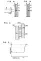
- transparent electrodes 13 and 14 are arranged on the inner surfaces of a pair of glass substrates 11 and 12 as shown in Fig. la and a liquid crystal 15 having a smectic phase is filled therebetween.
- a laser beam 16 emitted from an argon (Ar) laser or a yttrium-aluminum-garnet (YAG) laser is focused on the display panel through a lens 17 to heat the smectic liquid crystal 15 of a area 18 to be displayed, thereby rendering it an isotropic liquid crystal phase.
- the laser beam is removed to quickly cool the liquid crystal to the smectic phase.
- orientations of the liquid crystal molecules are disturbed and a region 19 which exhibits a strong scattering property is produced. Since this scattered state persists stably, a desired image information can be stored.
- the thermal writing type display device can write a desired image information on the liquid crystal elements by the scan and the modulation of the laser beam, and local erasure is attained by the application of an electric field.
- a display device it is preferable as a display device but it does not have a function to read out the stored image information or a function to output the information to an external device such as a computer and it is merely used as an input device of an image infromation signal.
- the other known liquid crystal devices also have only the function of displaying the image and they are not used as the information output devices.
- a capacitance of a dielectric material such as a liquid crystal having a smectic phase differs between an initial state and a write state, and means for detecting the capacitance is provided.
- dielectric material hereinused means a dielectric material the capacitance of which changes by the application of an electric field or a heat and the capacitance does not change but maintained or stored for a predetermined time period after the removal of the electric field or the heat.
- dielectric material examples include a liquid crystal having the smectic A phase, a liquid crystal having the cholesteric phase or PLZT. It is preferable to use a liquid crystal having the smectic A phase which can write the information at a relatively low temperature and has a long store time.
- a liquid crystal panel 200 comprises a pair of substrates 230 and 240 having electrodes 210 and 220 on opposing surfaces thereof and having a gap of approximately 10 ⁇ m therebetween, in which a liquid crystal 250 having a smectic A phase is filled.
- the substrates 230 and 240 may be glass plates or plastic plates, or the non-viewing substrate may be an opaque substrate such as a Si-substrate and the viewing substrate may be a transparent substrate such as a glass plate or a plastic plate.
- the electrodes 210 and 220 may be transparent conductive films such as mixture of indium oxide and tin oxide, or the electrode on the viewing substrate may be the transparent conductive film and the other electrode may be a metal such as At or Cr.
- the liquid crystal material may be mixture including where R is an alkali radical) which exhibit a positive dielectric anisotropy and the smectic A phase at room temperatures and changes from the smectic phase to a nematic phase at 42°C and from the nematic phase to an isotropic liquid phase at 45°C.
- R is an alkali radical
- liquid crystals having the smectic A phase are mixture of 4, 4' alchoxy biphnyl carboxylic acid alkyl ester and 4, 4' alkyl cyanotran and mixture of 4-alchoxy phenyl-4'-alkyl benzoic acid ester and p,p'-alkyl cyano biphenyl.
- dichronic dye is added to the liquid crystal, a viewing angle property of display is improved and it is desirable to the display device.
- Fig. 3 shows an optical characteristic of the liquid crystal having the smectic phase.
- the liquid crystal having the smectic phase When the liquid crystal having the smectic phase is heated, it exhibits an isotropic liquid phase (point c) and an essentially transparent state.
- the liquid crystal layer When the liquid crystal layer is cooled while a sufficient voltage is applied thereto, it exhibits a smectic phase (point a) and an essentially transparent state, and this state is retained (non-write state).
- the present inventors have found that when the voltage applied to the liquid crystal layer is changed in the course of cooling of the liquid crystal layer, the amount of scatter changes so that a tonality is imparted to the display.
- the inventors have also found that a static capacitance of the liquid crystal having the smectic phase does not substantially change for several days to several months after the electric field or the heat has been removed.
- Interfaces between the electrodes 210 and 220 and the liquid crystal having the smectic phase are treated with silane surface active agent so that they are homeotropically oriented, that is, the liquid crystal molecules having the smectic phase are oriented in a direction perpendicularly to the substrates, although they may be oriented in a direction parallel to the substrates.
- the liquid crystal material is not limited to the liquid crystal having the smectic phase but it may be other liquid crystal such as a liquid crystal having a cholesteric phase whose orientation is changed by the application of an external field and retained for a predetermined time period after the external field has been removed.
- Fig. 4 shows capacitance detecting means to be connected to the liquid crystal panel 200. It comprises a detection signal application circuit 310 and a signal detection circuit 320, and a detected information signal is produced at an output terminal 330.
- a laser pen 350 which can focus a laser beam at any point.
- the laser pen 350 comprises an optical fiber which guides the laser beam from a laser beam source and a focusing lens, or it may comprises an integral structure of a semiconductor laser 360 and a focusing lens 370.
- the inventors have found that the information can be written by condensing a laser power of no less than 100 mW onto the surface of the liquid crystal.
- FIG. 5 An embodiment of the capacitance detection means is shown in Fig. 5.
- the detection signal application circuit 310 is a sinusoidal wave oscillator 41 and the signal detection circuit 320 comprises a current-voltage converter circuit 42, a rectifier-filter circuit 43 and a comparator circuit 44.
- FIG. 5 An equivalent circuit when the opposing electrodes of the liquid crystal panel 200 is regarded as a capacitor is shown in Fig. 5.
- a capacitance of'the opposing electrodes of the liquid crystal panel in the initial state (non-write state) is represented by C NW and that in the write state is represented by C W .
- a specific dielectric constant of the liquid crystal layer is approximately equal to a specific dielectric constant ⁇ // in the long-axis direction of the liquid crystal molecules.
- the specific dielectric constant of the liquid crystal layer is equal to a three-dimensional average of the ⁇ // and a specific dielectric constant ⁇ ⁇ in the short- axis direction of the liquid crystal molecules, that is, ( ⁇ // + 2 ⁇ ⁇ )/3.
- This current I LC is converted to a voltage signal by the current-voltage converter circuit at the first stage of the signal detection circuit 320 and converted to a D.C. voltage by the rectifier-filter circuit 43 at the next stage, and it is supplied to the comparator circuit 44 at the final stage.
- the comparator circuit 44 compares the input voltage with a reference voltage and produces a compare result. As described above, the capacitance of the capacitor 43 is smaller in the write state than in the non-write state. Accordingly, if the reference voltage is properly selected, the output is at "low” level in the write state and at "high” level in the non-write state.
- the orientation of the liquid crystal can be detected.
- FIG. 6 shows a sectional view of a second embodiment of the present invention.
- An optical system 20 for writing an information signal such as an image signal in the liquid crystal elements comprises a laser 21 as a heat source, a modulator 22 for modulating a laser beam, an X-direction and Y-direction deflector for deflecting the laser beam to a desired direction, and a lens 24 for focusing the laser beam on the liquid crystal elements.
- the laser 21 may be a YAG laser having an output power of 1 W in a signal mode and a beam divergence of no more than 1 mrad.
- the modulator 22 may be an acoustic-optical modulator and the deflector 23 may be a plane mirror (galvanometer) which can control an angle by a current.
- the deflector 23 may be a plane mirror (galvanometer) which can control an angle by a current.
- the liquid crystal panel 30 is similar to that shown in Fig. 2. That is, a pair of glass or plastic substrates 31 and 32 are arranged to leave a gap of approximately 10 ⁇ m therebetween and a liquid crystal 35 having a smectic phase is filled therein with a perpendicular orientation to the substrates.
- a difference from the liquid crystal panel 200 shown in Fig. 2 resides in the number of electrodes.
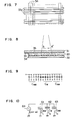
- the pair of glass substrates 31 and 32 each has transparent X and Y electrodes 33 and 34 of stripe shape extending in X and Y directions and cells formed by the opposing X and Y electrode portions and the liquid crystal portions therebetween are arranged in a matrix as a whole.
- the inventors irradiated a laser beam having an output power of approximately 50 mW to the surface of the liquid crystal panel 30 and got an excellent display of the information signal.
- Fig. 8 illustrates the orientation of the liquid crystal molecules when the position of the laser beam is moved from A to A' in the liquid crystal device of Fig. 7 to render the portion irradiated by the laser beam to assume the write state.
- the orientation of the liquid crystal molecules in the write state is disordered as opposed to that in the non-write state.
- the liquid crystal molecules are oriented perpendicularly (homeotropic orientation) by the perpendicular orientation treatment in the manufacture of the liquid crystal device, although they may be oriented parallel to the substrates.
- the smectic liquid crystal has the positive dielectric anisotropy.
- the specific dielectric constant E in the long-axis direction of the liquid crystal molecules is larger than the specific dielectric constant ⁇ ⁇ in the short- axis direction. Since the liquid crystal molecules are oriented vertically to the electrodes in the non-write state, the dielectric constant of the liquid crystal layer can be substantially regarded as ⁇ // . In the wirte state, since the orientation of the liquid crystal molecules is disordered, the dielectric constant of the liquid crystal layer is smaller than ⁇ // depending on the degree of disturbance. Assuming that they are perfectly randomly oriented, the dielectric constant is equal to ( ⁇ // + 2 ⁇ ⁇ )/3 .
- the liquid crystal panel of the cross-section shown in Fig. 8 can be regarded as capacitors having first ends thereof connected in common.
- the capacitances thereof differ depending on the difference of the dielectric constants due to the difference of the orientations between the write state and the non-write state.
- the static capacitance C w of the cell in the write state differs from the capacitance CNW of the cell in the non-write state as shown in Fig. 8.
- C w is smaller than C NW . If the orientation is parallel, C W is larger than C NW .
- the difference in the static capacitance is electrically read-out to recognize and output the written information signal.
- FIG. 10 An embodiment of means for detecting the capacitance of the opposing portions of the X electrodes and the Y electrodes is shown in Fig. 10.
- Fig. 10 the first ends of three cells (capacitors) 61, 62 and 63 are connected in common.
- an A.C. voltage source 64 of E sin wt is connected to the common terminal, currents I 1 , I 2 and and I3 which flows from the respective cells to a ground are expressed by
- the currents I 1 , I 2 and I3 detected meet a relation of
- the current I is a sum of a current I 1 flowing from an X electrode X 2 to which a voltage source 72 is connected, through the cell C21 and a current I 2 which flows through cells C 22 , C 12 and C 11 as shown by a broken line in Fig. 11. Therefore, the current I is different from the current I 1 flowing through the cell C 21 which is to be detected.
- the X electrode X 1 is grounded, the X electrode X 2 is connected to a voltage source 83 and a potential at an input terminal (point A) of the signal detection circuit 81 is kept substantially at a ground potential. Since the X electrode X and the Y electrodes Y 1 and Y 2 which form the cells (capacitors) C 11 and C 12 are substantially at the ground potential, no current flows through the cells C 11 and C 12 . Thus, the cross-talk current I 2 shown in Fig. 11 is no longer flows. Accordingly, the current I which flows into the signal detection circuit 81 comprises only the current flowing through the cell C21 and hence the capacitance of the cell C 21 can be exactly detected. Accordingly, the write state of the cell corresponding to C21 can be exactly recognized.
- the capacitance of the cell C 22 can be similarly detected by the signal detection circuit 82, and the state of the cell connected to the electrode X 2 is recognized.
- the voltage source 83 is connected to the electrode X 1 and the electrode X 2 is grounded, the state of the cell connected to the electrode X 1 is detected.
- the states of all cells can be recognized.
- the voltage of the voltage source 83 applied to detect the capacitance should be lower than the threshold of the liquid crystal in order to prevent the change of the capacitance.
- Fig. 13 shows an example of 3-rows by 3-columns matrix.
- the write and non-write states of the cells connected to the electrode X 1 are determined.
- the electrode X 2 is connected to the voltage source X 2 and the electrodes X 1 and X 3 are grounded, the write and non-write states of the cell connected to the electrode X 2 are determined.
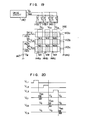
- Fig. 14 shows an embodiment of the signal detection circuit. It comprises a current-voltage converter circuit having an operational amplifier 101, a rectifier circuit 102, a filter circuit 103 and a comparator circuit 104, and detects an A.C. current flowing into an input terminal 100 to produce a "1" or "0" signal at an output terminal 201.
- a potential at the input terminal 100 is substantially ground potential, the cross-talk current is prevented as described above and an excellent detection circuit is provided.
- Figs. 15a and 15b show waveforms in the circuit of Fig. 14.
- Fig. 15a shows the detection of the capacitance C w of the cell in the write state and
- Fig. 15b shows the detection of the capacitance C NW of the cell in the non-write state, where C w ⁇ C NW .
- the operational amplifier 101 acts as a current amplifier. Since the input terminal 100 is at a virtual ground potential as described above, a voltage v a is zero. The current I is converted to a voltage v b which is rectified by a diode of the rectifier circuit, which produces a voltage v. It is filtered by the filter circuit 103 to produce a substantially D.C. voltage v d . By selecting a reference voltage V Ref of the comparator circuit 104 as shown by a broken line in Figs. 15a and 15b, an output voltage v e of the comparator circuit 104 is "0" for the write state cell of Fig. 15a and "1" for the non-write state cell of Fig. 15b. Thus, the static capacitance can be determined.
- the half-tone in the image display may be determined by changing the reference voltage V Ref .
- Fig. 16 shows an embodiment of an overall device which uses the 3 rows by 3 columns matrix shown in Fig. 13, and Fig. 17 shows waveforms in the circuit of Fig. 16.
- Switches S l , S 2 and S 3 sequentially select the X electrodes, starting from X 1 , which are held at the ground potential, by control signals SC 1 , SC 2 and SC 3 , and connect the selected X electrode to the voltage source 83.
- Signal detection circuits 91, 92 and 93 each has the circuit construction as shown in Fig. 13.
- Fig. 18 shows a third embodiment for writing the information signal, in which the like numerals to those shown in Fig. 6 designate the like elements.
- the present embodiment uses a write pen 113 having a semiconductor laser 111 and a focusing optical system 112 to write information signals such as image signals to cells of a liquid crystal panel 30 in a direction shown by an arrow.
- the written information signals are outputted to an external device in the same manner as that described above.
- the present invention can make the entire device more compact.
- a structure of a liquid crystal panel 146 is identical to that of the liquid crystal panel shown in Figs. 6 and 7.
- Switches 142a - 142c are connected to first terminals of X electrodes 143a - 143c formed on one substrate and second terminals are connected to ground (0 volt).
- Switch pairs 141a - 141c are connected to Y electrodes 144a - 144c formed on the other substrate.
- the switches 142a - 142c are connected to a heating power supply 147 and the switch pairs l4la - 141c are connected to a drive circuit 140, which produces a selection voltage V s and a non-selection voltage V NS ( V s ⁇ V NS in effective value).
- the voltage V s changes around the point c to point b in Fig. 3, and it is around zero volt in the present embodiment.
- the voltage V NS changes around the point c to point a in Fig. 3 and it is not limited to a pulse wave as shown in Fig. 20 but it may be a sine wave or an intermittent pulse wave. In order to prevent degradation of the liquid crystal, an A.C. waveform having a zero average value is preferable.
- the switch pairs 141a - 141c are turned off and the switch 142a is turned on for a predetermined time to apply the heating voltage V W to the X electrode 143a.
- the X electrode 143a is heated and the liquid crystal is heated by a joule heat so that it shifts from the smectic phase to the isotropic liquid phase.
- FIG. 21 Other embodiment of the information write means for the liquid crystal panel is shown in Fig. 21 and operational waveforms thereof are shown in Fig. 22.
- numeral 120 denotes a Y electrode drive circuit and numeral 121 denotes an X electrode drive circuit, which comprises two-channel switches for switching a voltage source V H for heating the X electrodes.
- Numeral 122 denotes switches which are turned on when the switches of the circuit 121 select the heating voltage source V H .
- voltages as shown in Fig. 22 are applied to the left ends of the X electrodes X 1 , X 2 , Across X n .
- the switches select the heating voltage source V H , and at second halves they select an A.C. voltage source 123.
- the X 1 selection time t l one of the switches 122 corresponding to the selected row electrode is turned on in the first half time period t 11 .
- the switch 121 selects the A.C.
- Fig. 24 shows other embodiment which integrates the information write and read circuits described above.
- Switches 102a - 102c are connected to first ends of X electrodes 77a - 77c. First input terminals of the switches 102a - 102c are connected to an X electrode drive circuit 100 and the second input terminals are connected to a detection signal application circuit 310.
- Second ends of the X electrodes 77a - 77c are connected to switches 106a - 106c.
- Switches 103a - 103c are connected to Y electrodes 76a - 76c.
- First input terminals of the switches 103a - 103c are connected to a Y electrode drive circuit 104 and the second input terminals are connected to a static capacitance detection circuit 330.
- the switches 102a - 102c select the X electrode drive circuit 100 and the switches 103a - 103c select the Y electrode drive circuit 104.
- laser beam writing may be used.
- the switches 106a - 106c are turned off, and in the heating write mode shown in Figs. 19 and 21, the switches 106a - 106c are turned on.
- the switches 103a - 103c select the detection signal application circuit 310 and the static capacitance detection circuit 330.
- the switches 106a - 106c are turned off.
- a desired image is written into and displayed by the liquid panel by the external circuit by heating the electrodes and an operator can add, correct or delete a desired information by a laser pen and the edited information is read out to the external circuit.
- liquid crystal having the smectic phase has been described in the present embodiment, other dielectric material such as a liquid crystal having a cholesteric phase or a PLZT whose static capacitance changes by the application of electric field or heat and stored for a predetermined time after the removal of the electric field or heat may be used in the present invention.
- the means for changing the static capacitance of the dielectric material is not limited to the heating means but it may be other means such as electric field means or current means which can vary the capacitance of the dielectric material.
- the information holding device made of the smectic liquid crystal is provided with the information reading function so that the information can be inputted and outputted.
- the information holding device having the picture cells arranged in the X-Y matrix is not affected by the cross-talk current so that the information can be inputted and outputted with the simple circuit.
Landscapes
- Engineering & Computer Science (AREA)
- Computer Hardware Design (AREA)
- Liquid Crystal (AREA)
- Devices For Indicating Variable Information By Combining Individual Elements (AREA)
Applications Claiming Priority (2)
| Application Number | Priority Date | Filing Date | Title |
|---|---|---|---|
| JP144713/82 | 1982-08-23 | ||
| JP57144713A JPS5934587A (ja) | 1982-08-23 | 1982-08-23 | 液晶装置 |
Publications (3)
| Publication Number | Publication Date |
|---|---|
| EP0103170A2 true EP0103170A2 (de) | 1984-03-21 |
| EP0103170A3 EP0103170A3 (en) | 1986-12-03 |
| EP0103170B1 EP0103170B1 (de) | 1989-11-23 |
Family
ID=15368556
Family Applications (1)
| Application Number | Title | Priority Date | Filing Date |
|---|---|---|---|
| EP83107895A Expired EP0103170B1 (de) | 1982-08-23 | 1983-08-10 | Informationsfesthaltungsanordnung |
Country Status (4)
| Country | Link |
|---|---|
| US (1) | US4548474A (de) |
| EP (1) | EP0103170B1 (de) |
| JP (1) | JPS5934587A (de) |
| DE (1) | DE3380887D1 (de) |
Cited By (4)
| Publication number | Priority date | Publication date | Assignee | Title |
|---|---|---|---|---|
| US4733370A (en) * | 1983-05-25 | 1988-03-22 | Hitachi, Ltd. | Information holding device |
| US4815035A (en) * | 1986-04-08 | 1989-03-21 | Trw Inc. | Scrolling liquid crystal spatial light modulator |
| EP0311502A1 (de) * | 1987-10-09 | 1989-04-12 | Thomson-Csf | Programmierbares Neuronennetzwerk mit ferroelektrischem Polymer |
| EP0425321A3 (en) * | 1989-10-27 | 1993-02-24 | The Mead Corporation | Liquid crystal cells and their use for recording information or for projecting an image |
Families Citing this family (10)
| Publication number | Priority date | Publication date | Assignee | Title |
|---|---|---|---|---|
| JPH0693166B2 (ja) * | 1984-09-05 | 1994-11-16 | 株式会社日立製作所 | 液晶素子 |
| US4690509A (en) * | 1984-10-02 | 1987-09-01 | Control Interface Company Limited | Waveforms on a liquid crystal display |
| US4668049A (en) * | 1984-12-18 | 1987-05-26 | Itt Corporation | Illumination for a scattering type liquid crystal display |
| JPH07120143B2 (ja) * | 1986-06-04 | 1995-12-20 | キヤノン株式会社 | 表示パネルの情報読出し法及び表示パネルの情報読出し装置 |
| US5029983A (en) * | 1986-12-06 | 1991-07-09 | Semiconductor Energy Laboratory Co., Ltd. | Liquid crystal device with a smectic chiral liquid crystal |
| JPS63175832A (ja) * | 1987-01-16 | 1988-07-20 | Hosiden Electronics Co Ltd | アクテイブマトリクス液晶表示装置 |
| US5233446A (en) * | 1987-03-31 | 1993-08-03 | Canon Kabushiki Kaisha | Display device |
| US5170270A (en) * | 1989-09-07 | 1992-12-08 | Sharp Corporation | Image writing device |
| US5247378A (en) * | 1991-06-07 | 1993-09-21 | Peter Miller | Optical retarder having means for determining the retardance of the cell corresponding to the sensed capacitance thereof |
| JP2823757B2 (ja) * | 1992-11-26 | 1998-11-11 | シャープ株式会社 | 不揮発性記録装置 |
Family Cites Families (7)
| Publication number | Priority date | Publication date | Assignee | Title |
|---|---|---|---|---|
| US3118133A (en) * | 1960-04-05 | 1964-01-14 | Bell Telephone Labor Inc | Information storage matrix utilizing a dielectric of pressure changeable permittivity |
| US3460103A (en) * | 1966-11-22 | 1969-08-05 | Radiation Inc | Ferroelectric memory device |
| US4150396A (en) * | 1974-09-06 | 1979-04-17 | Thomson-Csf | Erasable thermo-optic storage display of a transmitted color image |
| JPS5225230A (en) * | 1975-08-20 | 1977-02-25 | Fuji Electrochemical Co Ltd | Method of producing sealed battery |
| JPS5419739A (en) * | 1977-07-14 | 1979-02-14 | Canon Inc | Indicating circuit for focus adjusting condition of camera |
| GB1549584A (en) * | 1978-03-02 | 1979-08-08 | Standard Telephones Cables Ltd | Temperature responsive device |
| US4224615A (en) * | 1978-09-14 | 1980-09-23 | Texas Instruments Incorporated | Method of using a liquid crystal display device as a data input device |
-
1982
- 1982-08-23 JP JP57144713A patent/JPS5934587A/ja active Pending
-
1983
- 1983-08-10 EP EP83107895A patent/EP0103170B1/de not_active Expired
- 1983-08-10 DE DE8383107895T patent/DE3380887D1/de not_active Expired
- 1983-08-10 US US06/521,900 patent/US4548474A/en not_active Expired - Lifetime
Cited By (5)
| Publication number | Priority date | Publication date | Assignee | Title |
|---|---|---|---|---|
| US4733370A (en) * | 1983-05-25 | 1988-03-22 | Hitachi, Ltd. | Information holding device |
| US4815035A (en) * | 1986-04-08 | 1989-03-21 | Trw Inc. | Scrolling liquid crystal spatial light modulator |
| EP0311502A1 (de) * | 1987-10-09 | 1989-04-12 | Thomson-Csf | Programmierbares Neuronennetzwerk mit ferroelektrischem Polymer |
| US4873455A (en) * | 1987-10-09 | 1989-10-10 | Thomson-Csf | Programmable ferroelectric polymer neural network |
| EP0425321A3 (en) * | 1989-10-27 | 1993-02-24 | The Mead Corporation | Liquid crystal cells and their use for recording information or for projecting an image |
Also Published As
| Publication number | Publication date |
|---|---|
| JPS5934587A (ja) | 1984-02-24 |
| EP0103170A3 (en) | 1986-12-03 |
| DE3380887D1 (en) | 1989-12-28 |
| US4548474A (en) | 1985-10-22 |
| EP0103170B1 (de) | 1989-11-23 |
Similar Documents
| Publication | Publication Date | Title |
|---|---|---|
| US4548474A (en) | Information holding device | |
| US4902107A (en) | Ferroelectric liquid crystal optical device having temperature compensation | |
| US5633652A (en) | Method for driving optical modulation device | |
| US4649517A (en) | Information holding device | |
| US4733370A (en) | Information holding device | |
| JPS60144721A (ja) | 画像形成装置 | |
| GB2204172A (en) | Electro optical modulation devices | |
| JP2003500707A (ja) | 双安定液晶表示装置の高速アドレス | |
| US4981340A (en) | Method and apparatus for readout of information from display panel | |
| US4499458A (en) | Liquid crystal display device associating two addressing modes | |
| JPS59216126A (ja) | 液晶装置 | |
| JPS6373228A (ja) | 光学変調素子の駆動法 | |
| US4221471A (en) | Liquid crystal memory device and method of utilizing same | |
| US5231282A (en) | Optical writing type liquid crystal light valve and writing apparatus therefor | |
| EP0402944A2 (de) | Lichtgesteuertes Flüssigkristall-Lichtventil | |
| US5093737A (en) | Method for driving a ferroelectric optical modulation device therefor to apply an erasing voltage in the first step | |
| JP2924623B2 (ja) | 光書き込み型液晶表示記録装置 | |
| US4722594A (en) | Two-dimensional optical information processing apparatus | |
| US3806897A (en) | Electro-optic imaging system | |
| JPH0431373B2 (de) | ||
| JPS6031121A (ja) | 液晶装置 | |
| JPH0150916B2 (de) | ||
| JPS6128927A (ja) | 液晶熱書込み投射表示方法及び装置 | |
| JPH0453293B2 (de) | ||
| JPS61143788A (ja) | アクテイブマトリクス方式における液晶表示パネル |
Legal Events
| Date | Code | Title | Description |
|---|---|---|---|
| PUAI | Public reference made under article 153(3) epc to a published international application that has entered the european phase |
Free format text: ORIGINAL CODE: 0009012 |
|
| AK | Designated contracting states |
Designated state(s): CH DE FR GB LI NL |
|
| PUAL | Search report despatched |
Free format text: ORIGINAL CODE: 0009013 |
|
| AK | Designated contracting states |
Kind code of ref document: A3 Designated state(s): CH DE FR GB LI NL |
|
| 17P | Request for examination filed |
Effective date: 19861204 |
|
| 17Q | First examination report despatched |
Effective date: 19871119 |
|
| GRAA | (expected) grant |
Free format text: ORIGINAL CODE: 0009210 |
|
| AK | Designated contracting states |
Kind code of ref document: B1 Designated state(s): CH DE FR GB LI NL |
|
| REF | Corresponds to: |
Ref document number: 3380887 Country of ref document: DE Date of ref document: 19891228 |
|
| ET | Fr: translation filed | ||
| PLBE | No opposition filed within time limit |
Free format text: ORIGINAL CODE: 0009261 |
|
| STAA | Information on the status of an ep patent application or granted ep patent |
Free format text: STATUS: NO OPPOSITION FILED WITHIN TIME LIMIT |
|
| 26N | No opposition filed | ||
| PGFP | Annual fee paid to national office [announced via postgrant information from national office to epo] |
Ref country code: FR Payment date: 19990617 Year of fee payment: 17 |
|
| PGFP | Annual fee paid to national office [announced via postgrant information from national office to epo] |
Ref country code: CH Payment date: 19990622 Year of fee payment: 17 |
|
| PGFP | Annual fee paid to national office [announced via postgrant information from national office to epo] |
Ref country code: GB Payment date: 19990625 Year of fee payment: 17 |
|
| PGFP | Annual fee paid to national office [announced via postgrant information from national office to epo] |
Ref country code: NL Payment date: 19990630 Year of fee payment: 17 |
|
| PGFP | Annual fee paid to national office [announced via postgrant information from national office to epo] |
Ref country code: DE Payment date: 19990930 Year of fee payment: 17 |
|
| PG25 | Lapsed in a contracting state [announced via postgrant information from national office to epo] |
Ref country code: GB Free format text: LAPSE BECAUSE OF NON-PAYMENT OF DUE FEES Effective date: 20000810 |
|
| PG25 | Lapsed in a contracting state [announced via postgrant information from national office to epo] |
Ref country code: LI Free format text: LAPSE BECAUSE OF NON-PAYMENT OF DUE FEES Effective date: 20000831 Ref country code: CH Free format text: LAPSE BECAUSE OF NON-PAYMENT OF DUE FEES Effective date: 20000831 |
|
| PG25 | Lapsed in a contracting state [announced via postgrant information from national office to epo] |
Ref country code: NL Free format text: LAPSE BECAUSE OF NON-PAYMENT OF DUE FEES Effective date: 20010301 |
|
| GBPC | Gb: european patent ceased through non-payment of renewal fee |
Effective date: 20000810 |
|
| REG | Reference to a national code |
Ref country code: CH Ref legal event code: PL |
|
| PG25 | Lapsed in a contracting state [announced via postgrant information from national office to epo] |
Ref country code: FR Free format text: LAPSE BECAUSE OF NON-PAYMENT OF DUE FEES Effective date: 20010430 |
|
| NLV4 | Nl: lapsed or anulled due to non-payment of the annual fee |
Effective date: 20010301 |
|
| PG25 | Lapsed in a contracting state [announced via postgrant information from national office to epo] |
Ref country code: DE Free format text: LAPSE BECAUSE OF NON-PAYMENT OF DUE FEES Effective date: 20010501 |
|
| REG | Reference to a national code |
Ref country code: FR Ref legal event code: ST |