EP0103220A1 - Induktiv beheizter Giesskanal - Google Patents
Induktiv beheizter Giesskanal Download PDFInfo
- Publication number
- EP0103220A1 EP0103220A1 EP83108361A EP83108361A EP0103220A1 EP 0103220 A1 EP0103220 A1 EP 0103220A1 EP 83108361 A EP83108361 A EP 83108361A EP 83108361 A EP83108361 A EP 83108361A EP 0103220 A1 EP0103220 A1 EP 0103220A1
- Authority
- EP
- European Patent Office
- Prior art keywords
- channel
- sleeve
- graphite susceptor
- casting
- susceptor sleeve
- Prior art date
- Legal status (The legal status is an assumption and is not a legal conclusion. Google has not performed a legal analysis and makes no representation as to the accuracy of the status listed.)
- Granted
Links
Images

Classifications
-
- H—ELECTRICITY
- H05—ELECTRIC TECHNIQUES NOT OTHERWISE PROVIDED FOR
- H05B—ELECTRIC HEATING; ELECTRIC LIGHT SOURCES NOT OTHERWISE PROVIDED FOR; CIRCUIT ARRANGEMENTS FOR ELECTRIC LIGHT SOURCES, IN GENERAL
- H05B6/00—Heating by electric, magnetic or electromagnetic fields
- H05B6/02—Induction heating
- H05B6/10—Induction heating apparatus, other than furnaces, for specific applications
- H05B6/105—Induction heating apparatus, other than furnaces, for specific applications using a susceptor
- H05B6/108—Induction heating apparatus, other than furnaces, for specific applications using a susceptor for heating a fluid
-
- B—PERFORMING OPERATIONS; TRANSPORTING
- B22—CASTING; POWDER METALLURGY
- B22D—CASTING OF METALS; CASTING OF OTHER SUBSTANCES BY THE SAME PROCESSES OR DEVICES
- B22D35/00—Equipment for conveying molten metal into beds or moulds
- B22D35/06—Heating or cooling equipment
Definitions
- the present invention relates to the channel or the chute for casting a metal alloy with a high casting temperature, at least equal to 1400 ° C., in a mold.
- a metal alloy can be a super-alloy or an alloyed or low-alloyed steel.
- Superalloys fall into three categories: austenitic steels and alloys containing more than 20% iron, i.e. essentially composed of an austenite of iron, nickel, chromium or iron, chromium, nickel, cobalt, and alloys containing less than 20% iron, either nickel-based or cobalt-based.
- Superalloys still contain elements capable of forming carbides or inter-metallic phases: molybdenum, tungsten, vanadium, niobium, titanium, aluminum. Their main interest is their mechanical and chemical resistance, for increasingly high temperatures, that is to say above 900 or 1000 ° C. Their creep resistance is appreciated.
- the pouring channel of such an alloy can be that of a melting furnace or can be connected to a casting ladle in a foundry.
- a metal alloy with a high casting temperature solidifies quickly when the temperature drops.
- a furnace is used as a melting device. rotating or tilting in order to tilt and empty the chute between two successive flows by lowering and returning the liquid metal inside the heated enclosure of the oven.
- an inductor in the form of a coil or solenoid embedded in the refractory lining of the pouring spout, over its entire length, in order to induce a secondary heating current in the liquid alloy when it fills the chute just before and during a casting, and thus reduce the risks of solidification of the liquid metal alloy on the path of the casting chute.
- a chute provided with a flooded inductor is no longer heating in the absence of an alloy or of a liquid metal, between two successive flows, when the chute is raised to bring the liquid metal alloy down to the furnace.
- the risk of starting to solidify remains when the metal alloy enters the insufficiently heated casting chute.
- the problem is therefore posed of eliminating the risk of cooling and solidification of a metal alloy with a casting temperature at least equal to 1400 ° C. in a pouring channel, between two successive castings of a mold, by heating the channel. even when it does not contain an alloy or liquid metal.
- induction heating is preferred to heating by electrical resistances, the inductor suitably cooled causing no problems of expansion when it is embedded in the refractory lining, and the supply of current to the inductor, therefore to the channel, despite the high power required, also not posing any problems due to the interposition between the channel and the source of electric current of an aperiodic generator receiving this electric current at high
- the subject of the invention is therefore an improved casting channel with a view to solving this problem.
- This channel of the closed cross-section type comprising over its entire length a coil or solenoid-shaped inductor, the cooled turns of which are embedded in the refractory lining of the channel and traversed by a primary electric current supplied by an aperiodic generator, being characterized in that, around the casting bed of the channel and coaxially with said channel, is disposed a graphite susceptor sleeve through which an induced or secondary heating current flows when the inductor is supplied with primary current.
- the pouring channel is heated by induction when the inductor is traversed by a primary electric current, even when the liquid metal alloy is not introduced into the channel, so that the channel can be heated in advance, even before the first casting, and of course between two successive castings at a temperature ensuring the fluidity of the metal alloy at high casting temperature when the latter is introduced into the channel.
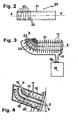
- the invention is applied to an electric melting furnace 1, of known type, rotating or tilting by means of a cradle 2 in an arc of a circle carried by rollers 3 (only one is shown), themselves mounted on a base frame 4.
- the oven 1 is of the reverberatory type with an arch 6 which reverberates the heat.
- cutaway is shown a part of the refractory lining 7 of the furnace 1 and of the capacity of the enclosure 8.
- In tearing away, is shown a part of the refractory lining 7 of the furnace 1 and of the capacity 8 which opens towards the pouring orifice liquid metal by a conduit 9.
- the conduit 9 is itself connected to an external pouring chute 10 with a metal box, fixed at one of its ends by a flange 11 removably to the furnace 1 proper and supported at the other end by a vertical stand A possibly adjustable in height by means not shown, for example of the screw-nut and handwheel type.
- the chute 10 comprises, as known, a refractory lining 12, for example made of silico-aluminous rammed earth, providing a duct or cylindrical pouring channel 13, of closed cross section connected to the duct 9.
- the channel 13, of axis XX produced as described below, comprises a straight part whose general direction is tiltable on either side of the horizontal during the tilting of the furnace 1 and a bent part 14 rising towards the high and opening onto the upper face of the chute 10 by a pouring orifice 15.
- a mold B represented by its outline exterior in phantom. The mold B is applied to the pouring orifice 15 by a pressure from the plate P actuated for example by a jack not shown.
- the capacity 8 of the furnace is placed under pressure of an inert gas such as argon or nitrogen so as to ensure the displacement of the liquid metal alloy up to the pouring orifice by adjusting the pressure without risk of oxidizing the liquid metal alloy in contact with this gas.
- an inert gas such as argon or nitrogen
- the chute 10 (or the channel 13) is of the heating type.
- an inductor 17, in the form of a coil or a solenoid (Fig. 1 and 3) metallic, made of copper, is embedded in the refractory lining 12, coaxially with the axis XX in along the bent outline of the channel 13 over almost the entire length of the channel 13, but leaving a large annular space around the channel 13, the turns of the inductor 17 having a diameter significantly greater than the outside diameter of the channel 13.
- the turns of the inductor 17 are internally cooled by a stream of water not shown, which eliminates any problem of expansion therefore of embedding of the inductor inside the refractory lining 12.
- the ends of the turns of the inductor 17 are connected to the two terminals 18 of an aperiodic generator 19 of electric current.
- an aperiodic generator 19 of electric current Conventionally, induction heating of the liquid metal alloy is obtained when this alloy completely fills the channel 13 and the coil 17 is supplied with electric current: the primary is the coil 17 and the secondary is the liquid metal alloy .
- a graphite sleeve 20 coaxial with the channel 13 therefore of axis XX, this sleeve 20, said susceptor in fact constituting the secondary in the induction system of which the coil 17 is the primary.
- the susceptor sleeve 20 is embedded or inserted, being placed with wide dimensional tolerances, on the refractory lining 12, in the vicinity of the internal wall forming the flow bed of the liquid metal alloy, but not constituting the bed d 'flow.
- the channel 13 is finished in the form described below.
- a sleeve 16 bent continuous and smooth, made of refractory material is applied as an internal coating of the susceptor sleeve 20 of which it covers the interstices between segments 23 opposite the contact of the sleeve 20 with the refractory lining 12.
- the sleeve 16 therefore constitutes the precise finish of the channel 13 even if the lining 12 itself has an internal cavity produced with wide dimensional tolerances. In other words, the sleeve 16 constitutes the flow bed of the liquid metal alloy with which it is intended to be in direct contact.
- the furnace 1 is preferably tilted or inclined so that the pouring chute 10 has its straight part in the raised position or inclined upwards in order to prevent liquid metal from entering the channel. 13.
- the oven is therefore tilted to the maximum (Fig. 4) and the chute 10 no longer rests on the stand A.
- the electric current supplied by the generator 19 passes through the primary coil 17 which induces the secondary heating current in the graphite susceptor tube 20. This in turn heats the coating sleeve 16 by contact.
- the furnace 1 When the melting of the metallic charge of the furnace 1 is finished, the furnace 1 is tilted in the position of FIG. 1, for casting until the chute 10 is supported on the stand A.
- the liquid metal rushes into the preheated casting channel 13, without rising to the orifice 15 on which the mold B since the neutral gas pressure above the charge of liquid metal in the furnace 1 is kept at a low value precisely adjusted so that the level of the liquid metal is lower than that of the orifice 15.
- the inductor 17, still supplied with electric current by the generator 19, then works with the liquid metal which, traversed by an induced secondary current, is heated and maintained at the desired temperature substantially greater than 1400 ° C., until the the neutral gas pressure is raised in the oven 1. with a view to raising the liquid metal above the orifice 15, to introduce it into the mold B and fill the latter.
- the metal or liquid alloy contained in the flow channel 13 or traversing it remains heated in all circumstances to a temperature almost as high as that which prevails inside the furnace 1.
- the invention is also applicable to induction heating, in the absence of liquid metal, of a channel oven - channel or an insulated channel fed by a simple ladle, neither heated nor heated.
Landscapes
- Electromagnetism (AREA)
- Engineering & Computer Science (AREA)
- Mechanical Engineering (AREA)
- Physics & Mathematics (AREA)
- General Induction Heating (AREA)
- Furnace Details (AREA)
- Vehicle Interior And Exterior Ornaments, Soundproofing, And Insulation (AREA)
- Steam Or Hot-Water Central Heating Systems (AREA)
- Manufacture And Refinement Of Metals (AREA)
- Organic Insulating Materials (AREA)
- Filters For Electric Vacuum Cleaners (AREA)
- Furnace Housings, Linings, Walls, And Ceilings (AREA)
- Organic Low-Molecular-Weight Compounds And Preparation Thereof (AREA)
- Heating, Cooling, Or Curing Plastics Or The Like In General (AREA)
- Crucibles And Fluidized-Bed Furnaces (AREA)
Priority Applications (1)
| Application Number | Priority Date | Filing Date | Title |
|---|---|---|---|
| AT83108361T ATE19213T1 (de) | 1982-09-13 | 1983-08-25 | Induktiv beheizter giesskanal. |
Applications Claiming Priority (2)
| Application Number | Priority Date | Filing Date | Title |
|---|---|---|---|
| FR8215556A FR2532866B1 (fr) | 1982-09-13 | 1982-09-13 | Chenal de coulee chauffe par induction |
| FR8215556 | 1982-09-13 |
Publications (2)
| Publication Number | Publication Date |
|---|---|
| EP0103220A1 true EP0103220A1 (de) | 1984-03-21 |
| EP0103220B1 EP0103220B1 (de) | 1986-04-16 |
Family
ID=9277460
Family Applications (1)
| Application Number | Title | Priority Date | Filing Date |
|---|---|---|---|
| EP83108361A Expired EP0103220B1 (de) | 1982-09-13 | 1983-08-25 | Induktiv beheizter Giesskanal |
Country Status (13)
| Country | Link |
|---|---|
| US (1) | US4475721A (de) |
| EP (1) | EP0103220B1 (de) |
| JP (1) | JPS5970460A (de) |
| AT (1) | ATE19213T1 (de) |
| DE (1) | DE3363074D1 (de) |
| DK (1) | DK162326C (de) |
| ES (1) | ES525437A0 (de) |
| FI (1) | FI73154C (de) |
| FR (1) | FR2532866B1 (de) |
| IT (2) | IT1168830B (de) |
| NO (1) | NO160058C (de) |
| SU (1) | SU1373331A3 (de) |
| UA (1) | UA6008A1 (de) |
Cited By (8)
| Publication number | Priority date | Publication date | Assignee | Title |
|---|---|---|---|---|
| US5022150A (en) * | 1989-10-27 | 1991-06-11 | General Electric Company | Method for producing heat transfer tube with insitu heater |
| FR2670697A1 (fr) * | 1990-12-24 | 1992-06-26 | Pont A Mousson | Chenal pour la mise en óoeuvre d'un procede de coulee sous pression d'un alliage metallique. |
| EP0503237A1 (de) * | 1991-03-14 | 1992-09-16 | Didier-Werke Ag | Feuerfestes Formteil und dessen Verwendung |
| FR2701225A1 (fr) * | 1993-02-08 | 1994-08-12 | Seva | Procédé de fabrication d'un organe chauffant de transfert de métal liquide, organe chauffant, son application et son utilisation. |
| WO1995022240A1 (fr) * | 1994-02-14 | 1995-08-17 | Seva | Moyen et bati pour le prechauffage d'un conduit de coulee de metal |
| WO1996017703A1 (fr) * | 1994-12-09 | 1996-06-13 | Seva | Conduit de coulee de metal liquide, procede et dispositif pour l'homogeneisation du metal |
| US8056608B2 (en) | 2008-04-25 | 2011-11-15 | Goodwin Plc | Method of mitigating against thermal contraction induced cracking during casting of a super Ni alloy |
| KR101256720B1 (ko) * | 2008-04-04 | 2013-04-19 | 퀄컴 인코포레이티드 | 상위-레벨의 단일 주파수 네트워크를 사용하여 다중 주파수 네트워크에 대한 가이드 및 주파수 맵 정보의 통합 방법 및 장치 |
Families Citing this family (13)
| Publication number | Priority date | Publication date | Assignee | Title |
|---|---|---|---|---|
| US4795139A (en) * | 1987-07-13 | 1989-01-03 | Intersteel Technology, Inc. | Apparatus for tapping slag-free steel from a continuous melting furnace |
| DE3842690C2 (de) * | 1988-12-19 | 1998-04-30 | Didier Werke Ag | Feuerfeste Verbindung sowie Induktionsspule hierfür |
| JP2827126B2 (ja) * | 1989-11-25 | 1998-11-18 | 住友重機械工業株式会社 | 溶湯・溶滓の連続排出方法及びその装置 |
| US5202081A (en) * | 1990-04-17 | 1993-04-13 | Rolls-Royce Plc | Launder system for supplying molten metal and a launder nozzle |
| FR2666036A1 (fr) * | 1990-08-27 | 1992-02-28 | Pont A Mousson | Dispositif intermediaire pour la coulee de pieces moulees. |
| US5339329A (en) * | 1993-01-25 | 1994-08-16 | Armco Steel Company, L.P. | Induction heated meniscus coating vessel |
| US5495495A (en) * | 1995-05-25 | 1996-02-27 | Saint-Gobain/Norton Industrial Ceramics Corporation | Dense lining for coreless induction furnace |
| DE19829191A1 (de) * | 1998-06-30 | 2000-01-05 | Be Automation Giesereitechnik | Druckvergiesseinrichtung |
| DE10059744A1 (de) * | 2000-12-01 | 2002-06-06 | Km Europa Metal Ag | Verfahren zum gezielten Temperieren einer Gießrinne und Gießrinne zur Durchführung des Verfahrens |
| US6555801B1 (en) | 2002-01-23 | 2003-04-29 | Melrose, Inc. | Induction heating coil, device and method of use |
| EP1578551A2 (de) * | 2002-12-16 | 2005-09-28 | Irving I. Dardik | Systeme und verfahren zur elektromagnetischen beeinflussungeines elektrisch leitenden kontinuums |
| CN101292048A (zh) * | 2005-08-19 | 2008-10-22 | 先进金属技术有限公司 | 感应激励的热铸桶底部喷嘴 |
| DK4064790T3 (da) * | 2021-03-22 | 2023-09-25 | Karlsruher Inst Technologie | Varmesystem, anvendelse af et varmesystem, vindmølle og fremgangsmåde til opvarmning |
Citations (6)
| Publication number | Priority date | Publication date | Assignee | Title |
|---|---|---|---|---|
| DE1068432B (de) * | 1959-11-05 | |||
| FR2401103A1 (fr) * | 1977-04-30 | 1979-03-23 | Sumitomo Electric Industries | Procede et appareil de production de fibres de transmission optique |
| AU502023B1 (en) * | 1977-11-08 | 1979-07-12 | Mitsubishi Jidosha Kogyo Kabushiki Kaisha | Low pressure casting |
| US4174462A (en) * | 1978-03-30 | 1979-11-13 | Pearce Michael L | Induction furnaces for high temperature continuous melting applications |
| DE3025680A1 (de) * | 1980-07-07 | 1982-02-04 | Siemens AG, 1000 Berlin und 8000 München | Heizkoerper fuer einen hochtemperaturofen |
| GB2082879A (en) * | 1980-08-20 | 1982-03-10 | Plessey Co Ltd | Improvements in or relating to furnaces for producing semiconductor materials |
Family Cites Families (7)
| Publication number | Priority date | Publication date | Assignee | Title |
|---|---|---|---|---|
| US2882570A (en) * | 1956-05-22 | 1959-04-21 | Joseph B Brennan | Continuous vacuum casting |
| US3435992A (en) * | 1966-03-11 | 1969-04-01 | Tisdale Co Inc | Pouring nozzle for continuous casting liquid metal or ordinary steel |
| US3604598A (en) * | 1969-07-09 | 1971-09-14 | United States Steel Corp | Outlet passage construction for teeming vessels |
| US3623541A (en) * | 1969-10-29 | 1971-11-30 | William L Schmitz | Metal casting apparatus |
| JPS4921331A (de) * | 1972-06-17 | 1974-02-25 | ||
| JPS5252832A (en) * | 1975-10-27 | 1977-04-28 | Mitsubishi Heavy Ind Ltd | Holding device for molten metal in ladle |
| JPS5775277A (en) * | 1980-10-30 | 1982-05-11 | Toshiba Mach Co Ltd | Casting equipment |
-
1982
- 1982-09-13 FR FR8215556A patent/FR2532866B1/fr not_active Expired
-
1983
- 1983-08-25 DE DE8383108361T patent/DE3363074D1/de not_active Expired
- 1983-08-25 AT AT83108361T patent/ATE19213T1/de not_active IP Right Cessation
- 1983-08-25 EP EP83108361A patent/EP0103220B1/de not_active Expired
- 1983-08-31 US US06/528,002 patent/US4475721A/en not_active Expired - Lifetime
- 1983-09-06 DK DK405483A patent/DK162326C/da not_active IP Right Cessation
- 1983-09-07 ES ES525437A patent/ES525437A0/es active Granted
- 1983-09-08 NO NO833203A patent/NO160058C/no unknown
- 1983-09-09 JP JP58166433A patent/JPS5970460A/ja active Granted
- 1983-09-09 IT IT67935/83A patent/IT1168830B/it active
- 1983-09-09 FI FI833232A patent/FI73154C/fi not_active IP Right Cessation
- 1983-09-09 IT IT8353700U patent/IT8353700V0/it unknown
- 1983-09-12 SU SU833640699A patent/SU1373331A3/ru active
- 1983-09-12 UA UA3640699A patent/UA6008A1/uk unknown
Patent Citations (6)
| Publication number | Priority date | Publication date | Assignee | Title |
|---|---|---|---|---|
| DE1068432B (de) * | 1959-11-05 | |||
| FR2401103A1 (fr) * | 1977-04-30 | 1979-03-23 | Sumitomo Electric Industries | Procede et appareil de production de fibres de transmission optique |
| AU502023B1 (en) * | 1977-11-08 | 1979-07-12 | Mitsubishi Jidosha Kogyo Kabushiki Kaisha | Low pressure casting |
| US4174462A (en) * | 1978-03-30 | 1979-11-13 | Pearce Michael L | Induction furnaces for high temperature continuous melting applications |
| DE3025680A1 (de) * | 1980-07-07 | 1982-02-04 | Siemens AG, 1000 Berlin und 8000 München | Heizkoerper fuer einen hochtemperaturofen |
| GB2082879A (en) * | 1980-08-20 | 1982-03-10 | Plessey Co Ltd | Improvements in or relating to furnaces for producing semiconductor materials |
Cited By (14)
| Publication number | Priority date | Publication date | Assignee | Title |
|---|---|---|---|---|
| US5022150A (en) * | 1989-10-27 | 1991-06-11 | General Electric Company | Method for producing heat transfer tube with insitu heater |
| FR2670697A1 (fr) * | 1990-12-24 | 1992-06-26 | Pont A Mousson | Chenal pour la mise en óoeuvre d'un procede de coulee sous pression d'un alliage metallique. |
| EP0503237A1 (de) * | 1991-03-14 | 1992-09-16 | Didier-Werke Ag | Feuerfestes Formteil und dessen Verwendung |
| US5708257A (en) * | 1993-02-08 | 1998-01-13 | Seva | Heating device for transfer of liquid metal and process for manufacturing the device |
| WO1994017938A1 (fr) * | 1993-02-08 | 1994-08-18 | Seva | Procede de fabrication d'un organe chauffant de transfert de metal liquide, organe chauffant, son application et son utilisation |
| FR2701225A1 (fr) * | 1993-02-08 | 1994-08-12 | Seva | Procédé de fabrication d'un organe chauffant de transfert de métal liquide, organe chauffant, son application et son utilisation. |
| WO1995022240A1 (fr) * | 1994-02-14 | 1995-08-17 | Seva | Moyen et bati pour le prechauffage d'un conduit de coulee de metal |
| FR2720591A1 (fr) * | 1994-02-14 | 1995-12-01 | Seva | Moyen et bâti pour le préchauffage d'un conduit de coulée de métal. |
| US5799718A (en) * | 1994-02-14 | 1998-09-01 | Seva | Device and frame for preheating a metal casting channel |
| WO1996017703A1 (fr) * | 1994-12-09 | 1996-06-13 | Seva | Conduit de coulee de metal liquide, procede et dispositif pour l'homogeneisation du metal |
| FR2727883A1 (fr) * | 1994-12-09 | 1996-06-14 | Seva | Conduit de coulee de metal liquide, procede et dispositif pour l'homogeneisation du metal |
| US5853605A (en) * | 1994-12-09 | 1998-12-29 | Seva | Liquid metal pouring duct, process and device for homogenizing metal |
| KR101256720B1 (ko) * | 2008-04-04 | 2013-04-19 | 퀄컴 인코포레이티드 | 상위-레벨의 단일 주파수 네트워크를 사용하여 다중 주파수 네트워크에 대한 가이드 및 주파수 맵 정보의 통합 방법 및 장치 |
| US8056608B2 (en) | 2008-04-25 | 2011-11-15 | Goodwin Plc | Method of mitigating against thermal contraction induced cracking during casting of a super Ni alloy |
Also Published As
| Publication number | Publication date |
|---|---|
| FR2532866B1 (fr) | 1985-06-07 |
| DE3363074D1 (en) | 1986-05-22 |
| IT1168830B (it) | 1987-05-20 |
| US4475721A (en) | 1984-10-09 |
| DK162326B (da) | 1991-10-14 |
| ATE19213T1 (de) | 1986-05-15 |
| FI833232A0 (fi) | 1983-09-09 |
| DK405483A (da) | 1984-03-14 |
| IT8367935A1 (it) | 1985-03-09 |
| FI73154B (fi) | 1987-05-29 |
| FI73154C (fi) | 1987-09-10 |
| FI833232L (fi) | 1984-03-14 |
| NO160058C (no) | 1989-03-08 |
| UA6008A1 (uk) | 1994-12-29 |
| IT8367935A0 (it) | 1983-09-09 |
| JPH0380578B2 (de) | 1991-12-25 |
| FR2532866A1 (fr) | 1984-03-16 |
| NO160058B (no) | 1988-11-28 |
| ES8404217A1 (es) | 1984-05-16 |
| ES525437A0 (es) | 1984-05-16 |
| JPS5970460A (ja) | 1984-04-20 |
| NO833203L (no) | 1984-03-14 |
| EP0103220B1 (de) | 1986-04-16 |
| DK405483D0 (da) | 1983-09-06 |
| SU1373331A3 (ru) | 1988-02-07 |
| DK162326C (da) | 1992-03-09 |
| IT8353700V0 (it) | 1983-09-09 |
Similar Documents
| Publication | Publication Date | Title |
|---|---|---|
| EP0103220B1 (de) | Induktiv beheizter Giesskanal | |
| CA1106134A (fr) | Procede de coulee de metal | |
| FR2575683A1 (fr) | Procede et installation pour la fabrication continue de tuyaux en fonte a graphite spheroidal a structure controlee | |
| LU85846A1 (fr) | Dispositif de brassage de metal en fusion dans une installation de coulee continue | |
| WO1994026444A1 (fr) | Dispositif d'alimentation en metal en fusion, notamment en fonte, d'une machine de coulee, et installation de coulee integrant ce dispositif d'alimentation | |
| CH628544A5 (fr) | Procede et installation pour la coulee continue de produits tubulaires. | |
| EP0305426A1 (de) | Verfahren und vorrichtung zum giessen von flüssigem metall. | |
| CA2235202A1 (fr) | Repartiteur de coulee continue des metaux, du type comportant au moins une torche a plasma pour le rechauffage du metal | |
| WO1994026938A1 (fr) | Procede de fusion de ferraille dans un four electrique et installation pour la mise en ×uvre du procede | |
| FR2670697A1 (fr) | Chenal pour la mise en óoeuvre d'un procede de coulee sous pression d'un alliage metallique. | |
| CA2204137C (fr) | Une poche de chauffage et de coulee de metaux liquides | |
| BE1004282A6 (fr) | Dispositif de prechauffage d'une busette de coulee d'un metal en fusion et installation de coulee d'un metal equipee de ce dispositif. | |
| EP0468832A1 (de) | Ofen zum Halten der Temperatur und zur metallurgischen Behandlung | |
| EP0800427A1 (de) | Schmelzleitung, verfahren und vorrichtung zum homogenisieren von schmelze | |
| EP0857529A1 (de) | Metallrohre und Verfahren und Anlage zu deren Herstellung | |
| EP0745314B1 (de) | Vorrichtung und gestell zum vorwärmen eines giesskanals | |
| FR2534167A1 (fr) | Procede de fabrication en fonderie de pieces moulees en alliages metalliques oxydables | |
| EP0104499A1 (de) | Verfahren und Einrichtung zur Beladung eines Metallegierungsschmelzofens zur Speisung von Giessformen | |
| BE567532A (de) | ||
| FR2668967A1 (fr) | Machine de coulee a pression pulsatoire. | |
| Umeda et al. | Construction and operation of the No. 1 round billet CCM at Wakayama Works | |
| FR2658745A1 (fr) | Procede et dispositif de moulage d'un alliage metallique. | |
| FR2462221A1 (fr) | Procede de fabrication de pieces revetues et composites, notamment bimetalliques | |
| FR2547395A1 (fr) | Dispositif bruleur pour four de fusion metallurgique | |
| BE561010A (de) |
Legal Events
| Date | Code | Title | Description |
|---|---|---|---|
| PUAI | Public reference made under article 153(3) epc to a published international application that has entered the european phase |
Free format text: ORIGINAL CODE: 0009012 |
|
| AK | Designated contracting states |
Designated state(s): AT DE GB NL SE |
|
| 17P | Request for examination filed |
Effective date: 19840602 |
|
| GRAA | (expected) grant |
Free format text: ORIGINAL CODE: 0009210 |
|
| AK | Designated contracting states |
Kind code of ref document: B1 Designated state(s): AT DE GB NL SE |
|
| REF | Corresponds to: |
Ref document number: 19213 Country of ref document: AT Date of ref document: 19860515 Kind code of ref document: T |
|
| REF | Corresponds to: |
Ref document number: 3363074 Country of ref document: DE Date of ref document: 19860522 |
|
| PLBE | No opposition filed within time limit |
Free format text: ORIGINAL CODE: 0009261 |
|
| STAA | Information on the status of an ep patent application or granted ep patent |
Free format text: STATUS: NO OPPOSITION FILED WITHIN TIME LIMIT |
|
| 26N | No opposition filed | ||
| EAL | Se: european patent in force in sweden |
Ref document number: 83108361.3 |
|
| PGFP | Annual fee paid to national office [announced via postgrant information from national office to epo] |
Ref country code: NL Payment date: 19970721 Year of fee payment: 15 |
|
| PGFP | Annual fee paid to national office [announced via postgrant information from national office to epo] |
Ref country code: AT Payment date: 19970725 Year of fee payment: 15 |
|
| PGFP | Annual fee paid to national office [announced via postgrant information from national office to epo] |
Ref country code: GB Payment date: 19970819 Year of fee payment: 15 |
|
| PGFP | Annual fee paid to national office [announced via postgrant information from national office to epo] |
Ref country code: DE Payment date: 19970823 Year of fee payment: 15 |
|
| PGFP | Annual fee paid to national office [announced via postgrant information from national office to epo] |
Ref country code: SE Payment date: 19970825 Year of fee payment: 15 |
|
| PG25 | Lapsed in a contracting state [announced via postgrant information from national office to epo] |
Ref country code: GB Free format text: LAPSE BECAUSE OF NON-PAYMENT OF DUE FEES Effective date: 19980825 Ref country code: AT Free format text: LAPSE BECAUSE OF NON-PAYMENT OF DUE FEES Effective date: 19980825 |
|
| PG25 | Lapsed in a contracting state [announced via postgrant information from national office to epo] |
Ref country code: SE Free format text: LAPSE BECAUSE OF NON-PAYMENT OF DUE FEES Effective date: 19980826 |
|
| PG25 | Lapsed in a contracting state [announced via postgrant information from national office to epo] |
Ref country code: NL Free format text: LAPSE BECAUSE OF NON-PAYMENT OF DUE FEES Effective date: 19990301 |
|
| GBPC | Gb: european patent ceased through non-payment of renewal fee |
Effective date: 19980825 |
|
| EUG | Se: european patent has lapsed |
Ref document number: 83108361.3 |
|
| NLV4 | Nl: lapsed or anulled due to non-payment of the annual fee |
Effective date: 19990301 |
|
| PG25 | Lapsed in a contracting state [announced via postgrant information from national office to epo] |
Ref country code: DE Free format text: LAPSE BECAUSE OF NON-PAYMENT OF DUE FEES Effective date: 19990601 |