EP1528267A1 - Feststellvorrichtung - Google Patents
Feststellvorrichtung Download PDFInfo
- Publication number
- EP1528267A1 EP1528267A1 EP04023895A EP04023895A EP1528267A1 EP 1528267 A1 EP1528267 A1 EP 1528267A1 EP 04023895 A EP04023895 A EP 04023895A EP 04023895 A EP04023895 A EP 04023895A EP 1528267 A1 EP1528267 A1 EP 1528267A1
- Authority
- EP
- European Patent Office
- Prior art keywords
- outer ring
- load
- rod
- springs
- clamping
- Prior art date
- Legal status (The legal status is an assumption and is not a legal conclusion. Google has not performed a legal analysis and makes no representation as to the accuracy of the status listed.)
- Granted
Links
Images

Classifications
-
- F—MECHANICAL ENGINEERING; LIGHTING; HEATING; WEAPONS; BLASTING
- F15—FLUID-PRESSURE ACTUATORS; HYDRAULICS OR PNEUMATICS IN GENERAL
- F15B—SYSTEMS ACTING BY MEANS OF FLUIDS IN GENERAL; FLUID-PRESSURE ACTUATORS, e.g. SERVOMOTORS; DETAILS OF FLUID-PRESSURE SYSTEMS, NOT OTHERWISE PROVIDED FOR
- F15B15/00—Fluid-actuated devices for displacing a member from one position to another; Gearing associated therewith
- F15B15/20—Other details, e.g. assembly with regulating devices
- F15B15/26—Locking mechanisms
- F15B15/262—Locking mechanisms using friction, e.g. brake pads
Definitions
- the invention relates to a device for jamming a load under load Rod by means of at least one attacking the rod circumference Clamping element, wherein the clamping element conical at its outer periphery shaped and displaceable in a corresponding conical outer ring is guided, such that the clamping element when driving through the Rod is pressed in the load direction self-reinforcing against the rod.
- clamping devices are used, for example, for fixing lifting tables, Support cylinders, theater podiums and the like used. Often acting They also as fall protection for vertical axes of machine tools or handling equipment.
- the clamping devices are hydraulically or pneumatically in the open position held and effective at pressure drop. This will be the energy the decreasing load used to generate the clamping force.
- a clamping device with the features of the preamble of claim 1 is known from DE 38 11 225.
- the clamping elements in case of release of the rod in the direction of load taken, with the conical Outer contour of the clamping elements to a self-reinforcing static friction the rod generates.
- the clamping elements run while - as far as the rated load not significantly exceeded - not against a housing-fixed stop. Overloads can therefore destroy the clamping device cause plastic deformation. This property limits the possible uses in cases where overloads are excluded. Therefore this clamping device in particular not suitable, the kinetic energy a dissipating mass to dissipate, it blocks the clamping rod, but is not suitable for braking.
- the present invention is based on the object, a Clamping device to develop a precise limitation of the holding force allowed, in case of overload targeted slippage of the rod without Damage to the clamping device, in particular without plastic deformation the relevant parts. Furthermore, the inventive Clamping device by inexpensive and less sensitive to tolerances Distinguish structure.
- this is a conical bush, which has one or more axial slots in its effective area. It But it is not excluded, with several in the circumferential direction next to each other to operate arranged clamping elements.
- the outer ring surrounding the clamping elements is useful as a closed Ring formed, but could also consist of several parts, wherein But care must be taken to intercept the radial forces occurring.
- the clamping element only after exceeding the predetermined defined Load axially against its stop, it is recommended that the bias of the on the outer ring attacking feathers slightly higher than to choose it Holding the given defined load (nominal load) would be required.
- the spring travel is responsible for the bias of the outer ring Springs chosen so that the axial displacement of the outer ring the springs not yet presses into their blocking position, but the said Springs a defined force on the outer ring and thus a defined holding or generate braking force on the rod when the axial displacement of the Clamping element is completed.
- the clamping element can directly against the abovementioned stop to run. In the sense of a compact construction, it is recommended, however, the interpose for the release of the clamping element responsible release piston.
- the outer ring surrounding the clamping elements not only in unloaded condition, but also under load axially spaced from the release piston or to the stop is arranged, whereas the clamping element is always held in contact with the release piston. The latter takes place in that in the usual way by spring elements in the clamping direction is charged.
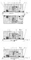
- the Housing 1 is fixedly mounted in a manner not shown, while the rod Fig. 2 illustrates the sliding machine element that is of the clamping device should be held.
- the rod 2 is surrounded by clamping elements, in the embodiment, the shape of a conical at its outer periphery Socket 3 have.
- This conical bush has axial slots in a known manner, so that it is elastic in the radial direction. It is in the inner cone of an outer ring 4, which will be discussed later and will be in the axial direction loaded by a cup spring package 5 in the clamping direction.
- the already mentioned outer ring 4 axially displaceable in the housing part 1a is guided and that it by springs 9 - preferably a Cup spring package - against the load direction, so in the sense'einer jamming the clamping bush 3 is biased.
- the disc springs 9 are in an annular Recess of the outer ring 4 is arranged and supported on her the Outer ring facing away from the end face on the aforementioned stop ring. 8 from.
- the bias of the disc springs 9 is chosen so that they only yield, if in the rod 2, a load occurs, which is above the rated load of Clamping device is located. This results in the following function:
- the clamping condition is triggered by the fact that the pressure in the cylinder chamber. 7 is switched off. This allows the springs 5, the cone ring to the right shift, this displacement movement by the movement of the rod 2 is supported and brings the known self-locking jamming.
- FIG. 4 shows the associated force / displacement diagram.
- the disc springs 9 Upon reaching the rated load or shortly thereafter, the disc springs 9 come to Effect. Therefore, here the characteristic curves in a flat area, namely until the clamping bush 3 abuts the dissolving piston 6 on the housing 1, as this is shown in FIG. With further increase in load finally the holding force the clamping device is exceeded and it slips, wherein the holding or braking force defined by the strength of the disc springs 9 becomes.
- the braking force is inventively greater than the weight of the moving Mass, therefore, an effective braking of the mass is guaranteed.
- the invention thus offers the advantage that while maintaining the conventional manufacturing tolerances a well-defined limit the clamping force can dictate, above the targeted slippage the pole is allowed.
Landscapes
- Engineering & Computer Science (AREA)
- Physics & Mathematics (AREA)
- Fluid Mechanics (AREA)
- Mechanical Engineering (AREA)
- General Engineering & Computer Science (AREA)
- Clamps And Clips (AREA)
- Lock And Its Accessories (AREA)
- Actuator (AREA)
Abstract
Description
- Figur 1
- einen Axialschnitt der Klemmvorrichtung in gelöstem Zustand,
- Figur 2
- den oberen Teil des Axialschnittes von Figur 1, jedoch in wirksamer Stellung, wobei die Last in der Stange unterhalb der Nennlast liegt;
- Figur 3
- einen Schnitt entsprechend Figur 2, wobei jedoch die Last in der Stange oberhalb der Nennlast liegt;
- Figur 4
- ein Kraft-/Weg-Diagramm der erfindungsgemäßen Klemmvorrichtung.
Claims (9)
- Vorrichtung zum Verklemmen einer unter Last stehenden Stange (2) mittels zumindest eines am Stangen-Umfang angreifenden Klemmelementes (3), wobei das Klemmelement (3) an seinem äußeren Umfang konisch geformt und in einem entsprechend konisch geformten Außenring (4) verschiebbar geführt ist, derart, dass das Klemmelement (3) bei Mitnahme durch die Stange (2) in Lastrichtung selbstverstärkend gegen die Stange (2) gepresst wird,
dadurch gekennzeichnet, dass der Außenring (4) axial verschiebbar in einem Gehäuse (1) geführt ist und entgegen der Lastrichtung durch Federn (9) vorgespannt ist und dass die Vorspannung der Federn (9) so bemessen ist, dass die Verschiebung des Außenringes (4) erst bei Überschreiten einer vorgegebenen, definierten Last in der Stange (2) eintritt. - Vorrichtung nach Anspruch 1,
dadurch gekennzeichnet, dass der theoretische Federweg der die Vorspannung bewirkenden Federn (9) größer ist als die maximale Axialverschiebung des Außenringes (4) unter Last. - Vorrichtung nach Anspruch 1,
dadurch gekennzeichnet, dass das Klemmelement (3) - vorzugsweise unter Zwischenschaltung zumindest eines Lösekolbens (6) - in Lastrichtung gegen einen Anschlag im Gehäuse (1) läuft. - Vorrichtung nach Anspruch 3,
dadurch gekennzeichnet, dass der Außenring (4) - unter Last - axial beabstandet zum Lösekolben (6) angeordnet ist. - Vorrichtung nach Anspruch 1,
dadurch gekennzeichnet, dass das Klemmelement (3) durch Federelemente (5) in Klemmrichtung belastet ist. - Vorrichtung nach Anspruch 3,
dadurch gekennzeichnet, dass das Klemmelement (3) axial am Lösekolben (6) anliegt. - Vorrichtung nach Anspruch 5,
dadurch gekennzeichnet, dass die für die Vorspannung des Außenringes (4) verantwortlichen Federn (9) um ein Mehrfaches stärker sind als die auf die Klemmbuchse (3) einwirkenden Federelemente (5). - Vorrichtung nach Anspruch 1,
dadurch gekennzeichnet, dass die für die Vorspannung des Außenringes (4) verantwortlichen Federn (9) so ausgelegt sind, dass die von ihnen erzeugte Haltekraft größer ist als die maximal auf die Stange (2) wirkende Last. - Vorrichtung nach Anspruch 1,
dadurch gekennzeichnet, dass sich die für die Vorspannung verantwortlichen Federn (9) an einem ortsfesten Anschlagring (8) abstützen, der zugleich den Stellweg des Lösekolbens (6) in der Löseposition begrenzt.
Applications Claiming Priority (2)
| Application Number | Priority Date | Filing Date | Title |
|---|---|---|---|
| DE10350225 | 2003-10-27 | ||
| DE10350225A DE10350225A1 (de) | 2003-10-27 | 2003-10-27 | Feststellvorrichtung |
Publications (2)
| Publication Number | Publication Date |
|---|---|
| EP1528267A1 true EP1528267A1 (de) | 2005-05-04 |
| EP1528267B1 EP1528267B1 (de) | 2007-01-24 |
Family
ID=34399573
Family Applications (1)
| Application Number | Title | Priority Date | Filing Date |
|---|---|---|---|
| EP04023895A Expired - Lifetime EP1528267B1 (de) | 2003-10-27 | 2004-10-07 | Feststellvorrichtung |
Country Status (6)
| Country | Link |
|---|---|
| US (1) | US7178639B2 (de) |
| EP (1) | EP1528267B1 (de) |
| JP (1) | JP2005132632A (de) |
| AT (1) | ATE352721T1 (de) |
| CA (1) | CA2485613A1 (de) |
| DE (2) | DE10350225A1 (de) |
Families Citing this family (17)
| Publication number | Priority date | Publication date | Assignee | Title |
|---|---|---|---|---|
| DE102005052755B4 (de) * | 2005-06-14 | 2014-11-20 | Bosch Rexroth Aktiengesellschaft | Hydraulisch betätigte Klemmeinheit und damit ausgeführte hydraulische Regelachse |
| DE102006004659A1 (de) | 2006-01-31 | 2007-08-02 | Sitema Gmbh & Co. Kg | Klemmvorrichtung |
| US20070246785A1 (en) * | 2006-04-20 | 2007-10-25 | Asml Netherlands B.V. | Locking device, adjustment mechanism and lithographic apparatus |
| US7748785B2 (en) * | 2007-09-27 | 2010-07-06 | Caterpillar Inc | Seat assembly including a mechanical strut and machine using same |
| US8020893B2 (en) * | 2007-09-27 | 2011-09-20 | Caterpillar Inc. | Steering column assembly including a mechanical strut and machine using same |
| DE102009011003A1 (de) * | 2009-03-02 | 2010-09-09 | Sitema Gmbh & Co. Kg | Klemmeinheit, insbesondere zur Verwendung als Formschließeinheit |
| DE102010023699B4 (de) | 2010-06-14 | 2012-02-23 | Pintsch Bubenzer Gmbh | Selbstverstärkende Bremseinrichtung |
| DE102010023701A1 (de) | 2010-06-14 | 2011-12-15 | Pintsch Bubenzer Gmbh | Lüftgerät für eine Bremseinrichtung |
| DE102010023700B4 (de) | 2010-06-14 | 2012-01-26 | Pintsch Bubenzer Gmbh | Stellvorrichtung für eine selbstverstärkende Bremseinrichtung und selbstverstärkende Bremseinrichtung |
| CN102425586B (zh) * | 2011-12-21 | 2014-12-10 | 徐州重型机械有限公司 | 一种液压油缸、液压系统及工程机械 |
| CN102628463A (zh) * | 2012-04-03 | 2012-08-08 | 无锡亿利大机械有限公司 | 机械自锁液压缸 |
| CN103362896B (zh) * | 2013-07-23 | 2016-08-24 | 云南兴长江实业有限公司 | 一种适合于液压油缸的安全锁定装置 |
| KR101512471B1 (ko) * | 2014-09-11 | 2015-04-16 | 한국뉴매틱(주) | 록-블록을 이용한 로드부재 록킹장치 |
| DE102015212851A1 (de) * | 2015-07-09 | 2017-01-12 | Sms Group Gmbh | Hydraulikzylinder, Vorrichtung zum Umformen von Werkstücken, Verwendung eines stirnseitigen Deckelteils |
| US10040152B2 (en) * | 2015-08-17 | 2018-08-07 | GM Global Technology Operations LLC | Mechanical lock for a work support |
| FI127824B (fi) * | 2018-01-22 | 2019-03-15 | Valmet Technologies Oy | Massavaimennin ja järjestely kuiturainakoneessa |
| CN110513377A (zh) * | 2019-09-19 | 2019-11-29 | 中国科学院武汉岩土力学研究所 | 锁紧装置和冲击设备 |
Citations (6)
| Publication number | Priority date | Publication date | Assignee | Title |
|---|---|---|---|---|
| EP0103555A1 (de) * | 1982-08-20 | 1984-03-21 | Atlas Copco Aktiebolag | Verriegelungsvorrichtung für einen Kolben |
| DE3811225A1 (de) * | 1988-04-02 | 1989-10-12 | Sitema | Hydraulische stuetzvorrichtung |
| DE3907780A1 (de) * | 1989-03-10 | 1990-09-13 | Bosch Gmbh Robert | Bremseinrichtung fuer eine kolbenstange |
| DE4126897A1 (de) * | 1991-08-14 | 1993-02-18 | Rexroth Mannesmann Gmbh | Hydraulisches klemmsystem |
| EP0538962A1 (de) * | 1991-10-25 | 1993-04-28 | Regie Nationale Des Usines Renault S.A. | Lenkvorrichtung für die Lenkräder eines Fahrzeuges |
| EP0731284A1 (de) * | 1995-03-09 | 1996-09-11 | Montanhydraulik GmbH | Klemmvorrichtung für zylindrische Teile |
Family Cites Families (8)
| Publication number | Priority date | Publication date | Assignee | Title |
|---|---|---|---|---|
| US2632425A (en) * | 1950-05-26 | 1953-03-24 | Reginald L Grover | Piston lock |
| DE1804857B2 (de) * | 1968-10-24 | 1971-11-25 | Hänchen, Siegfried, 7304 Ruit | Vorrichtung zur klemmung einer axial verschiebbaren kolben stange |
| DE2845266C2 (de) * | 1978-10-18 | 1983-03-03 | Ringspann Albrecht Maurer Kg, 6380 Bad Homburg | Sicherheitsfeststellbremse für hydraulische Aufzüge, Hebebühnen u.dgl. |
| DE3118449A1 (de) * | 1981-05-09 | 1982-12-02 | Sitema Gesellschaft für Sicherheitstechnik und Maschinenbau mbH, 7500 Karlsruhe | "klemmvorrichtung" |
| DE3707046A1 (de) * | 1987-03-05 | 1988-09-15 | Haenchen Kg Herbert | Klemmvorrichtung fuer stangen |
| DE8804418U1 (de) * | 1988-04-02 | 1988-05-19 | Sitema Gesellschaft für Sicherheitstechnik und Maschinenbau mbH, 7500 Karlsruhe | Brems- und Feststellvorrichtung |
| JP3856934B2 (ja) * | 1998-01-27 | 2006-12-13 | Smc株式会社 | ロック機構付き流体圧シリンダ |
| US6367591B1 (en) * | 1999-12-21 | 2002-04-09 | Caterpillar Inc. | Automatic brake clearance adjuster |
-
2003
- 2003-10-27 DE DE10350225A patent/DE10350225A1/de not_active Withdrawn
-
2004
- 2004-10-07 DE DE502004002749T patent/DE502004002749D1/de not_active Expired - Lifetime
- 2004-10-07 EP EP04023895A patent/EP1528267B1/de not_active Expired - Lifetime
- 2004-10-07 AT AT04023895T patent/ATE352721T1/de not_active IP Right Cessation
- 2004-10-21 CA CA002485613A patent/CA2485613A1/en not_active Abandoned
- 2004-10-27 JP JP2004311853A patent/JP2005132632A/ja active Pending
- 2004-10-27 US US10/974,269 patent/US7178639B2/en not_active Expired - Fee Related
Patent Citations (6)
| Publication number | Priority date | Publication date | Assignee | Title |
|---|---|---|---|---|
| EP0103555A1 (de) * | 1982-08-20 | 1984-03-21 | Atlas Copco Aktiebolag | Verriegelungsvorrichtung für einen Kolben |
| DE3811225A1 (de) * | 1988-04-02 | 1989-10-12 | Sitema | Hydraulische stuetzvorrichtung |
| DE3907780A1 (de) * | 1989-03-10 | 1990-09-13 | Bosch Gmbh Robert | Bremseinrichtung fuer eine kolbenstange |
| DE4126897A1 (de) * | 1991-08-14 | 1993-02-18 | Rexroth Mannesmann Gmbh | Hydraulisches klemmsystem |
| EP0538962A1 (de) * | 1991-10-25 | 1993-04-28 | Regie Nationale Des Usines Renault S.A. | Lenkvorrichtung für die Lenkräder eines Fahrzeuges |
| EP0731284A1 (de) * | 1995-03-09 | 1996-09-11 | Montanhydraulik GmbH | Klemmvorrichtung für zylindrische Teile |
Also Published As
| Publication number | Publication date |
|---|---|
| US7178639B2 (en) | 2007-02-20 |
| JP2005132632A (ja) | 2005-05-26 |
| DE10350225A1 (de) | 2005-05-19 |
| DE502004002749D1 (de) | 2007-03-15 |
| US20050087405A1 (en) | 2005-04-28 |
| CA2485613A1 (en) | 2005-04-27 |
| EP1528267B1 (de) | 2007-01-24 |
| ATE352721T1 (de) | 2007-02-15 |
Similar Documents
| Publication | Publication Date | Title |
|---|---|---|
| EP1528267B1 (de) | Feststellvorrichtung | |
| EP1707307B1 (de) | Schnellspannsystem | |
| EP2317178B1 (de) | Kugelgewindetrieb für eine Feststellbremse eines Kraftfahrzeuges | |
| DE102009008815B4 (de) | Reibgehemme mit querliegendem Käfig | |
| DE2123248A1 (de) | Axialaufhangesystem | |
| EP0219594B1 (de) | Druckmittelbetätigte Einrichtung | |
| EP3377796B1 (de) | Kupplungselement für eine kupplung zur verbindung von druckmittelleitungen | |
| DE102008035021A1 (de) | Greif- oder Spanneinheit | |
| WO1986005425A1 (fr) | Dispositif de serrage rapide | |
| DE102014204174B4 (de) | Drehmomentbegrenzende Rücklaufsperre | |
| DE102016116392B3 (de) | Greifer mit Dämpfungssystem zum Greifen eines Brennelementes | |
| DE2845266C2 (de) | Sicherheitsfeststellbremse für hydraulische Aufzüge, Hebebühnen u.dgl. | |
| DE2150726B2 (de) | Spindelpresse | |
| DE102009049920A1 (de) | Spannvorrichtung | |
| DE2736911A1 (de) | Vorrichtung zur aufnahme und umwandlung von energie | |
| EP1492958A1 (de) | Fluidbetätigter kontraktionsantrieb | |
| EP1342019B9 (de) | Federelement aus elastischem werkstoff, insbesondere aus kunststoff | |
| EP1776527B1 (de) | Verriegelungsvorrichtung für linearaktuatoren | |
| DE10344102B3 (de) | Federträger mit einer Zusatzfeder | |
| DE10330523A1 (de) | Vorrichtung zum Abstützen eines Statorwickelkopfs | |
| DE60206219T2 (de) | Linearer Strafferantrieb für einen Sicherheitsgurt | |
| DE19621197A1 (de) | Nachstellvorrichtung zur Hubbegrenzung eines Kolbens | |
| CH456676A (de) | Druckluftbremszylinder, insbesondere für Schienenfahrzeuge | |
| DE202013009442U1 (de) | Verschleißnachstellvorrichtung für Scheibenbremsen | |
| LU85612A1 (fr) | Greifvorrichtung fuer in das stichloch von metallurgischen ofen eintreibbare und aus diesem herausziehbare stangen,insbesondere abstichstangen |
Legal Events
| Date | Code | Title | Description |
|---|---|---|---|
| PUAI | Public reference made under article 153(3) epc to a published international application that has entered the european phase |
Free format text: ORIGINAL CODE: 0009012 |
|
| AK | Designated contracting states |
Kind code of ref document: A1 Designated state(s): AT BE BG CH CY CZ DE DK EE ES FI FR GB GR HU IE IT LI LU MC NL PL PT RO SE SI SK TR |
|
| AX | Request for extension of the european patent |
Extension state: AL HR LT LV MK |
|
| 17P | Request for examination filed |
Effective date: 20050810 |
|
| AKX | Designation fees paid |
Designated state(s): AT BE BG CH CY CZ DE DK EE ES FI FR GB GR HU IE IT LI LU MC NL PL PT RO SE SI SK TR |
|
| GRAP | Despatch of communication of intention to grant a patent |
Free format text: ORIGINAL CODE: EPIDOSNIGR1 |
|
| GRAS | Grant fee paid |
Free format text: ORIGINAL CODE: EPIDOSNIGR3 |
|
| GRAA | (expected) grant |
Free format text: ORIGINAL CODE: 0009210 |
|
| AK | Designated contracting states |
Kind code of ref document: B1 Designated state(s): AT BE BG CH CY CZ DE DK EE ES FI FR GB GR HU IE IT LI LU MC NL PL PT RO SE SI SK TR |
|
| PG25 | Lapsed in a contracting state [announced via postgrant information from national office to epo] |
Ref country code: PL Free format text: LAPSE BECAUSE OF FAILURE TO SUBMIT A TRANSLATION OF THE DESCRIPTION OR TO PAY THE FEE WITHIN THE PRESCRIBED TIME-LIMIT Effective date: 20070124 Ref country code: SI Free format text: LAPSE BECAUSE OF FAILURE TO SUBMIT A TRANSLATION OF THE DESCRIPTION OR TO PAY THE FEE WITHIN THE PRESCRIBED TIME-LIMIT Effective date: 20070124 Ref country code: DK Free format text: LAPSE BECAUSE OF FAILURE TO SUBMIT A TRANSLATION OF THE DESCRIPTION OR TO PAY THE FEE WITHIN THE PRESCRIBED TIME-LIMIT Effective date: 20070124 Ref country code: IE Free format text: LAPSE BECAUSE OF FAILURE TO SUBMIT A TRANSLATION OF THE DESCRIPTION OR TO PAY THE FEE WITHIN THE PRESCRIBED TIME-LIMIT Effective date: 20070124 Ref country code: NL Free format text: LAPSE BECAUSE OF FAILURE TO SUBMIT A TRANSLATION OF THE DESCRIPTION OR TO PAY THE FEE WITHIN THE PRESCRIBED TIME-LIMIT Effective date: 20070124 Ref country code: FI Free format text: LAPSE BECAUSE OF FAILURE TO SUBMIT A TRANSLATION OF THE DESCRIPTION OR TO PAY THE FEE WITHIN THE PRESCRIBED TIME-LIMIT Effective date: 20070124 |
|
| REG | Reference to a national code |
Ref country code: GB Ref legal event code: FG4D Free format text: NOT ENGLISH |
|
| REG | Reference to a national code |
Ref country code: CH Ref legal event code: EP |
|
| REG | Reference to a national code |
Ref country code: IE Ref legal event code: FG4D Free format text: LANGUAGE OF EP DOCUMENT: GERMAN |
|
| REF | Corresponds to: |
Ref document number: 502004002749 Country of ref document: DE Date of ref document: 20070315 Kind code of ref document: P |
|
| PG25 | Lapsed in a contracting state [announced via postgrant information from national office to epo] |
Ref country code: SE Free format text: LAPSE BECAUSE OF FAILURE TO SUBMIT A TRANSLATION OF THE DESCRIPTION OR TO PAY THE FEE WITHIN THE PRESCRIBED TIME-LIMIT Effective date: 20070424 |
|
| PG25 | Lapsed in a contracting state [announced via postgrant information from national office to epo] |
Ref country code: BG Free format text: LAPSE BECAUSE OF FAILURE TO SUBMIT A TRANSLATION OF THE DESCRIPTION OR TO PAY THE FEE WITHIN THE PRESCRIBED TIME-LIMIT Effective date: 20070425 |
|
| PG25 | Lapsed in a contracting state [announced via postgrant information from national office to epo] |
Ref country code: ES Free format text: LAPSE BECAUSE OF FAILURE TO SUBMIT A TRANSLATION OF THE DESCRIPTION OR TO PAY THE FEE WITHIN THE PRESCRIBED TIME-LIMIT Effective date: 20070505 |
|
| GBT | Gb: translation of ep patent filed (gb section 77(6)(a)/1977) |
Effective date: 20070417 |
|
| ET | Fr: translation filed | ||
| PG25 | Lapsed in a contracting state [announced via postgrant information from national office to epo] |
Ref country code: PT Free format text: LAPSE BECAUSE OF FAILURE TO SUBMIT A TRANSLATION OF THE DESCRIPTION OR TO PAY THE FEE WITHIN THE PRESCRIBED TIME-LIMIT Effective date: 20070625 |
|
| NLV1 | Nl: lapsed or annulled due to failure to fulfill the requirements of art. 29p and 29m of the patents act | ||
| REG | Reference to a national code |
Ref country code: IE Ref legal event code: FD4D |
|
| PG25 | Lapsed in a contracting state [announced via postgrant information from national office to epo] |
Ref country code: SK Free format text: LAPSE BECAUSE OF FAILURE TO SUBMIT A TRANSLATION OF THE DESCRIPTION OR TO PAY THE FEE WITHIN THE PRESCRIBED TIME-LIMIT Effective date: 20070124 |
|
| PLBE | No opposition filed within time limit |
Free format text: ORIGINAL CODE: 0009261 |
|
| STAA | Information on the status of an ep patent application or granted ep patent |
Free format text: STATUS: NO OPPOSITION FILED WITHIN TIME LIMIT |
|
| 26N | No opposition filed |
Effective date: 20071025 |
|
| PG25 | Lapsed in a contracting state [announced via postgrant information from national office to epo] |
Ref country code: CZ Free format text: LAPSE BECAUSE OF FAILURE TO SUBMIT A TRANSLATION OF THE DESCRIPTION OR TO PAY THE FEE WITHIN THE PRESCRIBED TIME-LIMIT Effective date: 20070124 Ref country code: RO Free format text: LAPSE BECAUSE OF FAILURE TO SUBMIT A TRANSLATION OF THE DESCRIPTION OR TO PAY THE FEE WITHIN THE PRESCRIBED TIME-LIMIT Effective date: 20070124 |
|
| BERE | Be: lapsed |
Owner name: SITEMA G.M.B.H. & CO. KG Effective date: 20071031 |
|
| PG25 | Lapsed in a contracting state [announced via postgrant information from national office to epo] |
Ref country code: GR Free format text: LAPSE BECAUSE OF FAILURE TO SUBMIT A TRANSLATION OF THE DESCRIPTION OR TO PAY THE FEE WITHIN THE PRESCRIBED TIME-LIMIT Effective date: 20070425 |
|
| PG25 | Lapsed in a contracting state [announced via postgrant information from national office to epo] |
Ref country code: MC Free format text: LAPSE BECAUSE OF NON-PAYMENT OF DUE FEES Effective date: 20071031 |
|
| PG25 | Lapsed in a contracting state [announced via postgrant information from national office to epo] |
Ref country code: BE Free format text: LAPSE BECAUSE OF NON-PAYMENT OF DUE FEES Effective date: 20071031 |
|
| PG25 | Lapsed in a contracting state [announced via postgrant information from national office to epo] |
Ref country code: EE Free format text: LAPSE BECAUSE OF FAILURE TO SUBMIT A TRANSLATION OF THE DESCRIPTION OR TO PAY THE FEE WITHIN THE PRESCRIBED TIME-LIMIT Effective date: 20070124 |
|
| PG25 | Lapsed in a contracting state [announced via postgrant information from national office to epo] |
Ref country code: AT Free format text: LAPSE BECAUSE OF NON-PAYMENT OF DUE FEES Effective date: 20071007 |
|
| REG | Reference to a national code |
Ref country code: CH Ref legal event code: PL |
|
| PGFP | Annual fee paid to national office [announced via postgrant information from national office to epo] |
Ref country code: GB Payment date: 20081024 Year of fee payment: 5 |
|
| PG25 | Lapsed in a contracting state [announced via postgrant information from national office to epo] |
Ref country code: CY Free format text: LAPSE BECAUSE OF FAILURE TO SUBMIT A TRANSLATION OF THE DESCRIPTION OR TO PAY THE FEE WITHIN THE PRESCRIBED TIME-LIMIT Effective date: 20070124 |
|
| PG25 | Lapsed in a contracting state [announced via postgrant information from national office to epo] |
Ref country code: LU Free format text: LAPSE BECAUSE OF NON-PAYMENT OF DUE FEES Effective date: 20071007 |
|
| PG25 | Lapsed in a contracting state [announced via postgrant information from national office to epo] |
Ref country code: TR Free format text: LAPSE BECAUSE OF FAILURE TO SUBMIT A TRANSLATION OF THE DESCRIPTION OR TO PAY THE FEE WITHIN THE PRESCRIBED TIME-LIMIT Effective date: 20070124 Ref country code: HU Free format text: LAPSE BECAUSE OF FAILURE TO SUBMIT A TRANSLATION OF THE DESCRIPTION OR TO PAY THE FEE WITHIN THE PRESCRIBED TIME-LIMIT Effective date: 20070725 |
|
| PG25 | Lapsed in a contracting state [announced via postgrant information from national office to epo] |
Ref country code: CH Free format text: LAPSE BECAUSE OF NON-PAYMENT OF DUE FEES Effective date: 20081031 Ref country code: LI Free format text: LAPSE BECAUSE OF NON-PAYMENT OF DUE FEES Effective date: 20081031 |
|
| PG25 | Lapsed in a contracting state [announced via postgrant information from national office to epo] |
Ref country code: GB Free format text: LAPSE BECAUSE OF NON-PAYMENT OF DUE FEES Effective date: 20091007 |
|
| REG | Reference to a national code |
Ref country code: DE Ref legal event code: R082 Ref document number: 502004002749 Country of ref document: DE Representative=s name: LEMCKE, BROMMER & PARTNER, PATENTANWAELTE PART, DE |
|
| REG | Reference to a national code |
Ref country code: DE Ref legal event code: R081 Ref document number: 502004002749 Country of ref document: DE Owner name: SITEMA GMBH & CO. KG, DE Free format text: FORMER OWNER: SITEMA GMBH & CO. KG, 76135 KARLSRUHE, DE Effective date: 20150311 Ref country code: DE Ref legal event code: R082 Ref document number: 502004002749 Country of ref document: DE Representative=s name: LEMCKE, BROMMER & PARTNER, PATENTANWAELTE PART, DE Effective date: 20150311 |
|
| REG | Reference to a national code |
Ref country code: FR Ref legal event code: CA Effective date: 20150330 |
|
| REG | Reference to a national code |
Ref country code: FR Ref legal event code: PLFP Year of fee payment: 12 |
|
| REG | Reference to a national code |
Ref country code: FR Ref legal event code: PLFP Year of fee payment: 13 |
|
| REG | Reference to a national code |
Ref country code: FR Ref legal event code: PLFP Year of fee payment: 14 |
|
| REG | Reference to a national code |
Ref country code: FR Ref legal event code: PLFP Year of fee payment: 15 |
|
| PGFP | Annual fee paid to national office [announced via postgrant information from national office to epo] |
Ref country code: IT Payment date: 20231031 Year of fee payment: 20 Ref country code: FR Payment date: 20231023 Year of fee payment: 20 Ref country code: DE Payment date: 20230920 Year of fee payment: 20 |
|
| REG | Reference to a national code |
Ref country code: DE Ref legal event code: R071 Ref document number: 502004002749 Country of ref document: DE |