EP0103622B1 - Procede et dispositif pour l'execution d'analyses - Google Patents
Procede et dispositif pour l'execution d'analyses Download PDFInfo
- Publication number
- EP0103622B1 EP0103622B1 EP83901134A EP83901134A EP0103622B1 EP 0103622 B1 EP0103622 B1 EP 0103622B1 EP 83901134 A EP83901134 A EP 83901134A EP 83901134 A EP83901134 A EP 83901134A EP 0103622 B1 EP0103622 B1 EP 0103622B1
- Authority
- EP
- European Patent Office
- Prior art keywords
- receptacle
- pressure
- reaction zone
- reagent
- reservoir
- Prior art date
- Legal status (The legal status is an assumption and is not a legal conclusion. Google has not performed a legal analysis and makes no representation as to the accuracy of the status listed.)
- Expired
Links
- 238000003556 assay Methods 0.000 title claims description 119
- 238000000034 method Methods 0.000 title claims description 73
- 238000006243 chemical reaction Methods 0.000 claims description 119
- 239000012530 fluid Substances 0.000 claims description 86
- 239000003153 chemical reaction reagent Substances 0.000 claims description 84
- 239000012491 analyte Substances 0.000 claims description 42
- 239000000126 substance Substances 0.000 claims description 41
- 239000007790 solid phase Substances 0.000 claims description 34
- 238000009739 binding Methods 0.000 claims description 27
- 230000027455 binding Effects 0.000 claims description 25
- 238000012546 transfer Methods 0.000 claims description 25
- 239000000376 reactant Substances 0.000 claims description 24
- 239000007788 liquid Substances 0.000 claims description 21
- 230000003028 elevating effect Effects 0.000 claims description 14
- 239000003446 ligand Substances 0.000 claims description 9
- 102000004169 proteins and genes Human genes 0.000 claims description 7
- 108090000623 proteins and genes Proteins 0.000 claims description 7
- 230000035484 reaction time Effects 0.000 claims description 7
- 230000002829 reductive effect Effects 0.000 claims description 6
- 125000006850 spacer group Chemical group 0.000 claims description 5
- 239000000203 mixture Substances 0.000 claims description 4
- 238000003746 solid phase reaction Methods 0.000 claims description 4
- 238000004891 communication Methods 0.000 claims description 3
- 238000010521 absorption reaction Methods 0.000 claims description 2
- 150000001409 amidines Chemical class 0.000 claims description 2
- 125000003277 amino group Chemical group 0.000 claims description 2
- 230000000295 complement effect Effects 0.000 claims description 2
- 238000002372 labelling Methods 0.000 claims 6
- ZHNUHDYFZUAESO-UHFFFAOYSA-N Formamide Chemical compound NC=O ZHNUHDYFZUAESO-UHFFFAOYSA-N 0.000 claims 2
- 238000007654 immersion Methods 0.000 claims 2
- 229920001184 polypeptide Polymers 0.000 claims 2
- 102000004196 processed proteins & peptides Human genes 0.000 claims 2
- 108090000765 processed proteins & peptides Proteins 0.000 claims 2
- 125000000524 functional group Chemical group 0.000 claims 1
- 239000000243 solution Substances 0.000 description 27
- 239000000523 sample Substances 0.000 description 19
- 239000000463 material Substances 0.000 description 14
- 238000003018 immunoassay Methods 0.000 description 13
- 239000007791 liquid phase Substances 0.000 description 13
- 238000013019 agitation Methods 0.000 description 10
- 230000002285 radioactive effect Effects 0.000 description 10
- 241000894007 species Species 0.000 description 10
- 238000001514 detection method Methods 0.000 description 9
- 239000007789 gas Substances 0.000 description 9
- 238000005192 partition Methods 0.000 description 9
- 102000005962 receptors Human genes 0.000 description 9
- 238000000926 separation method Methods 0.000 description 9
- 239000000427 antigen Substances 0.000 description 8
- 102000036639 antigens Human genes 0.000 description 8
- 108091007433 antigens Proteins 0.000 description 8
- 230000000694 effects Effects 0.000 description 8
- 238000005259 measurement Methods 0.000 description 8
- 239000012071 phase Substances 0.000 description 8
- 150000001875 compounds Chemical class 0.000 description 7
- 230000007246 mechanism Effects 0.000 description 7
- 210000002966 serum Anatomy 0.000 description 7
- 238000005406 washing Methods 0.000 description 7
- 239000000872 buffer Substances 0.000 description 6
- 239000012086 standard solution Substances 0.000 description 6
- XUIIKFGFIJCVMT-GFCCVEGCSA-N D-thyroxine Chemical compound IC1=CC(C[C@@H](N)C(O)=O)=CC(I)=C1OC1=CC(I)=C(O)C(I)=C1 XUIIKFGFIJCVMT-GFCCVEGCSA-N 0.000 description 5
- 102000004190 Enzymes Human genes 0.000 description 5
- 108090000790 Enzymes Proteins 0.000 description 5
- 230000003213 activating effect Effects 0.000 description 5
- -1 antibodies Proteins 0.000 description 5
- 230000008901 benefit Effects 0.000 description 5
- 238000010276 construction Methods 0.000 description 5
- 230000001965 increasing effect Effects 0.000 description 5
- PXIPVTKHYLBLMZ-UHFFFAOYSA-N Sodium azide Chemical compound [Na+].[N-]=[N+]=[N-] PXIPVTKHYLBLMZ-UHFFFAOYSA-N 0.000 description 4
- 101000874347 Streptococcus agalactiae IgA FC receptor Proteins 0.000 description 4
- 238000007792 addition Methods 0.000 description 4
- 239000013060 biological fluid Substances 0.000 description 4
- 230000005587 bubbling Effects 0.000 description 4
- 208000002672 hepatitis B Diseases 0.000 description 4
- 238000002360 preparation method Methods 0.000 description 4
- 238000003127 radioimmunoassay Methods 0.000 description 4
- 229940034208 thyroxine Drugs 0.000 description 4
- XUIIKFGFIJCVMT-UHFFFAOYSA-N thyroxine-binding globulin Natural products IC1=CC(CC([NH3+])C([O-])=O)=CC(I)=C1OC1=CC(I)=C(O)C(I)=C1 XUIIKFGFIJCVMT-UHFFFAOYSA-N 0.000 description 4
- 108090001008 Avidin Proteins 0.000 description 3
- PEDCQBHIVMGVHV-UHFFFAOYSA-N Glycerine Chemical compound OCC(O)CO PEDCQBHIVMGVHV-UHFFFAOYSA-N 0.000 description 3
- 238000013459 approach Methods 0.000 description 3
- 239000011324 bead Substances 0.000 description 3
- 230000009137 competitive binding Effects 0.000 description 3
- 230000003247 decreasing effect Effects 0.000 description 3
- 230000002255 enzymatic effect Effects 0.000 description 3
- 239000011521 glass Substances 0.000 description 3
- 238000011534 incubation Methods 0.000 description 3
- 238000002156 mixing Methods 0.000 description 3
- 229920000642 polymer Polymers 0.000 description 3
- 239000012488 sample solution Substances 0.000 description 3
- 239000000758 substrate Substances 0.000 description 3
- YBJHBAHKTGYVGT-ZKWXMUAHSA-N (+)-Biotin Chemical compound N1C(=O)N[C@@H]2[C@H](CCCCC(=O)O)SC[C@@H]21 YBJHBAHKTGYVGT-ZKWXMUAHSA-N 0.000 description 2
- 108010088751 Albumins Proteins 0.000 description 2
- 102000009027 Albumins Human genes 0.000 description 2
- IJGRMHOSHXDMSA-UHFFFAOYSA-N Atomic nitrogen Chemical compound N#N IJGRMHOSHXDMSA-UHFFFAOYSA-N 0.000 description 2
- 108060003951 Immunoglobulin Proteins 0.000 description 2
- 239000004743 Polypropylene Substances 0.000 description 2
- 239000004793 Polystyrene Substances 0.000 description 2
- UIIMBOGNXHQVGW-UHFFFAOYSA-M Sodium bicarbonate Chemical compound [Na+].OC([O-])=O UIIMBOGNXHQVGW-UHFFFAOYSA-M 0.000 description 2
- 230000002159 abnormal effect Effects 0.000 description 2
- 230000002411 adverse Effects 0.000 description 2
- 238000003149 assay kit Methods 0.000 description 2
- 239000012911 assay medium Substances 0.000 description 2
- 239000011248 coating agent Substances 0.000 description 2
- 238000000576 coating method Methods 0.000 description 2
- 238000010790 dilution Methods 0.000 description 2
- 239000012895 dilution Substances 0.000 description 2
- 238000011049 filling Methods 0.000 description 2
- 239000007850 fluorescent dye Substances 0.000 description 2
- 150000004676 glycans Chemical class 0.000 description 2
- 239000001307 helium Substances 0.000 description 2
- 229910052734 helium Inorganic materials 0.000 description 2
- SWQJXJOGLNCZEY-UHFFFAOYSA-N helium atom Chemical compound [He] SWQJXJOGLNCZEY-UHFFFAOYSA-N 0.000 description 2
- 208000006454 hepatitis Diseases 0.000 description 2
- 230000002706 hydrostatic effect Effects 0.000 description 2
- 150000002463 imidates Chemical class 0.000 description 2
- 230000001900 immune effect Effects 0.000 description 2
- 230000008105 immune reaction Effects 0.000 description 2
- 102000018358 immunoglobulin Human genes 0.000 description 2
- 239000011261 inert gas Substances 0.000 description 2
- 238000002955 isolation Methods 0.000 description 2
- 150000002605 large molecules Chemical class 0.000 description 2
- 229920002521 macromolecule Polymers 0.000 description 2
- 230000009871 nonspecific binding Effects 0.000 description 2
- 239000008188 pellet Substances 0.000 description 2
- 230000000737 periodic effect Effects 0.000 description 2
- 210000002381 plasma Anatomy 0.000 description 2
- 229920001155 polypropylene Polymers 0.000 description 2
- 229920001282 polysaccharide Polymers 0.000 description 2
- 239000005017 polysaccharide Substances 0.000 description 2
- 229920002223 polystyrene Polymers 0.000 description 2
- 230000008569 process Effects 0.000 description 2
- 238000001179 sorption measurement Methods 0.000 description 2
- 238000012289 standard assay Methods 0.000 description 2
- 210000001519 tissue Anatomy 0.000 description 2
- XLYOFNOQVPJJNP-UHFFFAOYSA-N water Substances O XLYOFNOQVPJJNP-UHFFFAOYSA-N 0.000 description 2
- 108010017384 Blood Proteins Proteins 0.000 description 1
- 102000004506 Blood Proteins Human genes 0.000 description 1
- 108091003079 Bovine Serum Albumin Proteins 0.000 description 1
- 102000014914 Carrier Proteins Human genes 0.000 description 1
- 108010010803 Gelatin Proteins 0.000 description 1
- 239000004677 Nylon Substances 0.000 description 1
- 241000283973 Oryctolagus cuniculus Species 0.000 description 1
- 102000016979 Other receptors Human genes 0.000 description 1
- 239000004698 Polyethylene Substances 0.000 description 1
- UIIMBOGNXHQVGW-DEQYMQKBSA-M Sodium bicarbonate-14C Chemical compound [Na+].O[14C]([O-])=O UIIMBOGNXHQVGW-DEQYMQKBSA-M 0.000 description 1
- ABBQHOQBGMUPJH-UHFFFAOYSA-M Sodium salicylate Chemical compound [Na+].OC1=CC=CC=C1C([O-])=O ABBQHOQBGMUPJH-UHFFFAOYSA-M 0.000 description 1
- ATJFFYVFTNAWJD-UHFFFAOYSA-N Tin Chemical compound [Sn] ATJFFYVFTNAWJD-UHFFFAOYSA-N 0.000 description 1
- 239000012042 active reagent Substances 0.000 description 1
- 150000001350 alkyl halides Chemical class 0.000 description 1
- 125000003368 amide group Chemical group 0.000 description 1
- 239000011805 ball Substances 0.000 description 1
- 230000004888 barrier function Effects 0.000 description 1
- 108091008324 binding proteins Proteins 0.000 description 1
- 239000012472 biological sample Substances 0.000 description 1
- 229960002685 biotin Drugs 0.000 description 1
- 235000020958 biotin Nutrition 0.000 description 1
- 239000011616 biotin Substances 0.000 description 1
- 210000004369 blood Anatomy 0.000 description 1
- 239000008280 blood Substances 0.000 description 1
- 229940098773 bovine serum albumin Drugs 0.000 description 1
- 239000008366 buffered solution Substances 0.000 description 1
- 150000001718 carbodiimides Chemical class 0.000 description 1
- 150000001735 carboxylic acids Chemical class 0.000 description 1
- 239000001913 cellulose Substances 0.000 description 1
- 229920002678 cellulose Polymers 0.000 description 1
- 239000012141 concentrate Substances 0.000 description 1
- 238000009833 condensation Methods 0.000 description 1
- 230000005494 condensation Effects 0.000 description 1
- 238000011109 contamination Methods 0.000 description 1
- 229920001577 copolymer Polymers 0.000 description 1
- 230000009849 deactivation Effects 0.000 description 1
- 230000001066 destructive effect Effects 0.000 description 1
- 238000009658 destructive testing Methods 0.000 description 1
- 238000011161 development Methods 0.000 description 1
- 230000018109 developmental process Effects 0.000 description 1
- 238000009792 diffusion process Methods 0.000 description 1
- 239000003085 diluting agent Substances 0.000 description 1
- 230000003292 diminished effect Effects 0.000 description 1
- 231100000673 dose–response relationship Toxicity 0.000 description 1
- 239000000975 dye Substances 0.000 description 1
- 230000008030 elimination Effects 0.000 description 1
- 238000003379 elimination reaction Methods 0.000 description 1
- 238000002474 experimental method Methods 0.000 description 1
- 230000006870 function Effects 0.000 description 1
- 229920000159 gelatin Polymers 0.000 description 1
- 239000008273 gelatin Substances 0.000 description 1
- 235000019322 gelatine Nutrition 0.000 description 1
- 235000011852 gelatine desserts Nutrition 0.000 description 1
- 230000005484 gravity Effects 0.000 description 1
- 231100000283 hepatitis Toxicity 0.000 description 1
- 239000003112 inhibitor Substances 0.000 description 1
- 239000006249 magnetic particle Substances 0.000 description 1
- 230000007257 malfunction Effects 0.000 description 1
- 238000012986 modification Methods 0.000 description 1
- 230000004048 modification Effects 0.000 description 1
- 150000002825 nitriles Chemical class 0.000 description 1
- 229910052757 nitrogen Inorganic materials 0.000 description 1
- 238000009659 non-destructive testing Methods 0.000 description 1
- 229920001778 nylon Polymers 0.000 description 1
- 230000003287 optical effect Effects 0.000 description 1
- 150000002894 organic compounds Chemical class 0.000 description 1
- 238000012856 packing Methods 0.000 description 1
- 239000002245 particle Substances 0.000 description 1
- 239000008363 phosphate buffer Substances 0.000 description 1
- 239000004033 plastic Substances 0.000 description 1
- 229920003023 plastic Polymers 0.000 description 1
- 229920000058 polyacrylate Polymers 0.000 description 1
- 229920002239 polyacrylonitrile Polymers 0.000 description 1
- 229920000573 polyethylene Polymers 0.000 description 1
- 229920000193 polymethacrylate Polymers 0.000 description 1
- 229920005862 polyol Polymers 0.000 description 1
- 150000003077 polyols Chemical class 0.000 description 1
- 239000004800 polyvinyl chloride Substances 0.000 description 1
- 229920000915 polyvinyl chloride Polymers 0.000 description 1
- 125000002924 primary amino group Chemical group [H]N([H])* 0.000 description 1
- 238000012545 processing Methods 0.000 description 1
- 238000010926 purge Methods 0.000 description 1
- 230000005855 radiation Effects 0.000 description 1
- 239000011541 reaction mixture Substances 0.000 description 1
- 238000004064 recycling Methods 0.000 description 1
- 230000003252 repetitive effect Effects 0.000 description 1
- 230000000717 retained effect Effects 0.000 description 1
- 238000012552 review Methods 0.000 description 1
- 210000003296 saliva Anatomy 0.000 description 1
- 238000007789 sealing Methods 0.000 description 1
- 230000035945 sensitivity Effects 0.000 description 1
- 229910000030 sodium bicarbonate Inorganic materials 0.000 description 1
- 235000017557 sodium bicarbonate Nutrition 0.000 description 1
- 229960004025 sodium salicylate Drugs 0.000 description 1
- 239000007787 solid Substances 0.000 description 1
- 230000009870 specific binding Effects 0.000 description 1
- 238000012360 testing method Methods 0.000 description 1
- 239000003656 tris buffered saline Substances 0.000 description 1
- 241001515965 unidentified phage Species 0.000 description 1
- 229920002554 vinyl polymer Polymers 0.000 description 1
Images



Classifications
-
- G—PHYSICS
- G01—MEASURING; TESTING
- G01N—INVESTIGATING OR ANALYSING MATERIALS BY DETERMINING THEIR CHEMICAL OR PHYSICAL PROPERTIES
- G01N35/00—Automatic analysis not limited to methods or materials provided for in any single one of groups G01N1/00 - G01N33/00; Handling materials therefor
- G01N35/10—Devices for transferring samples or any liquids to, in, or from, the analysis apparatus, e.g. suction devices, injection devices
- G01N35/1065—Multiple transfer devices
-
- G—PHYSICS
- G01—MEASURING; TESTING
- G01N—INVESTIGATING OR ANALYSING MATERIALS BY DETERMINING THEIR CHEMICAL OR PHYSICAL PROPERTIES
- G01N1/00—Sampling; Preparing specimens for investigation
- G01N1/28—Preparing specimens for investigation including physical details of (bio-)chemical methods covered elsewhere, e.g. G01N33/50, C12Q
- G01N1/38—Diluting, dispersing or mixing samples
-
- G—PHYSICS
- G01—MEASURING; TESTING
- G01N—INVESTIGATING OR ANALYSING MATERIALS BY DETERMINING THEIR CHEMICAL OR PHYSICAL PROPERTIES
- G01N33/00—Investigating or analysing materials by specific methods not covered by groups G01N1/00 - G01N31/00
- G01N33/48—Biological material, e.g. blood, urine; Haemocytometers
- G01N33/50—Chemical analysis of biological material, e.g. blood, urine; Testing involving biospecific ligand binding methods; Immunological testing
- G01N33/53—Immunoassay; Biospecific binding assay; Materials therefor
- G01N33/5302—Apparatus specially adapted for immunological test procedures
-
- G—PHYSICS
- G01—MEASURING; TESTING
- G01N—INVESTIGATING OR ANALYSING MATERIALS BY DETERMINING THEIR CHEMICAL OR PHYSICAL PROPERTIES
- G01N33/00—Investigating or analysing materials by specific methods not covered by groups G01N1/00 - G01N31/00
- G01N33/48—Biological material, e.g. blood, urine; Haemocytometers
- G01N33/50—Chemical analysis of biological material, e.g. blood, urine; Testing involving biospecific ligand binding methods; Immunological testing
- G01N33/53—Immunoassay; Biospecific binding assay; Materials therefor
- G01N33/543—Immunoassay; Biospecific binding assay; Materials therefor with an insoluble carrier for immobilising immunochemicals
- G01N33/54366—Apparatus specially adapted for solid-phase testing
-
- G—PHYSICS
- G01—MEASURING; TESTING
- G01N—INVESTIGATING OR ANALYSING MATERIALS BY DETERMINING THEIR CHEMICAL OR PHYSICAL PROPERTIES
- G01N35/00—Automatic analysis not limited to methods or materials provided for in any single one of groups G01N1/00 - G01N33/00; Handling materials therefor
-
- G—PHYSICS
- G01—MEASURING; TESTING
- G01N—INVESTIGATING OR ANALYSING MATERIALS BY DETERMINING THEIR CHEMICAL OR PHYSICAL PROPERTIES
- G01N35/00—Automatic analysis not limited to methods or materials provided for in any single one of groups G01N1/00 - G01N33/00; Handling materials therefor
- G01N2035/00465—Separating and mixing arrangements
- G01N2035/00534—Mixing by a special element, e.g. stirrer
- G01N2035/00544—Mixing by a special element, e.g. stirrer using fluid flow
-
- G—PHYSICS
- G01—MEASURING; TESTING
- G01N—INVESTIGATING OR ANALYSING MATERIALS BY DETERMINING THEIR CHEMICAL OR PHYSICAL PROPERTIES
- G01N35/00—Automatic analysis not limited to methods or materials provided for in any single one of groups G01N1/00 - G01N33/00; Handling materials therefor
- G01N35/10—Devices for transferring samples or any liquids to, in, or from, the analysis apparatus, e.g. suction devices, injection devices
- G01N2035/1027—General features of the devices
- G01N2035/1048—General features of the devices using the transfer device for another function
- G01N2035/1055—General features of the devices using the transfer device for another function for immobilising reagents, e.g. dried reagents
-
- G—PHYSICS
- G01—MEASURING; TESTING
- G01N—INVESTIGATING OR ANALYSING MATERIALS BY DETERMINING THEIR CHEMICAL OR PHYSICAL PROPERTIES
- G01N35/00—Automatic analysis not limited to methods or materials provided for in any single one of groups G01N1/00 - G01N33/00; Handling materials therefor
- G01N35/10—Devices for transferring samples or any liquids to, in, or from, the analysis apparatus, e.g. suction devices, injection devices
- G01N35/1079—Devices for transferring samples or any liquids to, in, or from, the analysis apparatus, e.g. suction devices, injection devices with means for piercing stoppers or septums
-
- Y—GENERAL TAGGING OF NEW TECHNOLOGICAL DEVELOPMENTS; GENERAL TAGGING OF CROSS-SECTIONAL TECHNOLOGIES SPANNING OVER SEVERAL SECTIONS OF THE IPC; TECHNICAL SUBJECTS COVERED BY FORMER USPC CROSS-REFERENCE ART COLLECTIONS [XRACs] AND DIGESTS
- Y10—TECHNICAL SUBJECTS COVERED BY FORMER USPC
- Y10S—TECHNICAL SUBJECTS COVERED BY FORMER USPC CROSS-REFERENCE ART COLLECTIONS [XRACs] AND DIGESTS
- Y10S436/00—Chemistry: analytical and immunological testing
- Y10S436/807—Apparatus included in process claim, e.g. physical support structures
-
- Y—GENERAL TAGGING OF NEW TECHNOLOGICAL DEVELOPMENTS; GENERAL TAGGING OF CROSS-SECTIONAL TECHNOLOGIES SPANNING OVER SEVERAL SECTIONS OF THE IPC; TECHNICAL SUBJECTS COVERED BY FORMER USPC CROSS-REFERENCE ART COLLECTIONS [XRACs] AND DIGESTS
- Y10—TECHNICAL SUBJECTS COVERED BY FORMER USPC
- Y10S—TECHNICAL SUBJECTS COVERED BY FORMER USPC CROSS-REFERENCE ART COLLECTIONS [XRACs] AND DIGESTS
- Y10S436/00—Chemistry: analytical and immunological testing
- Y10S436/807—Apparatus included in process claim, e.g. physical support structures
- Y10S436/808—Automated or kit
-
- Y—GENERAL TAGGING OF NEW TECHNOLOGICAL DEVELOPMENTS; GENERAL TAGGING OF CROSS-SECTIONAL TECHNOLOGIES SPANNING OVER SEVERAL SECTIONS OF THE IPC; TECHNICAL SUBJECTS COVERED BY FORMER USPC CROSS-REFERENCE ART COLLECTIONS [XRACs] AND DIGESTS
- Y10—TECHNICAL SUBJECTS COVERED BY FORMER USPC
- Y10S—TECHNICAL SUBJECTS COVERED BY FORMER USPC CROSS-REFERENCE ART COLLECTIONS [XRACs] AND DIGESTS
- Y10S436/00—Chemistry: analytical and immunological testing
- Y10S436/807—Apparatus included in process claim, e.g. physical support structures
- Y10S436/81—Tube, bottle, or dipstick
-
- Y—GENERAL TAGGING OF NEW TECHNOLOGICAL DEVELOPMENTS; GENERAL TAGGING OF CROSS-SECTIONAL TECHNOLOGIES SPANNING OVER SEVERAL SECTIONS OF THE IPC; TECHNICAL SUBJECTS COVERED BY FORMER USPC CROSS-REFERENCE ART COLLECTIONS [XRACs] AND DIGESTS
- Y10—TECHNICAL SUBJECTS COVERED BY FORMER USPC
- Y10S—TECHNICAL SUBJECTS COVERED BY FORMER USPC CROSS-REFERENCE ART COLLECTIONS [XRACs] AND DIGESTS
- Y10S436/00—Chemistry: analytical and immunological testing
- Y10S436/82—Hepatitis associated antigens and antibodies
-
- Y—GENERAL TAGGING OF NEW TECHNOLOGICAL DEVELOPMENTS; GENERAL TAGGING OF CROSS-SECTIONAL TECHNOLOGIES SPANNING OVER SEVERAL SECTIONS OF THE IPC; TECHNICAL SUBJECTS COVERED BY FORMER USPC CROSS-REFERENCE ART COLLECTIONS [XRACs] AND DIGESTS
- Y10—TECHNICAL SUBJECTS COVERED BY FORMER USPC
- Y10T—TECHNICAL SUBJECTS COVERED BY FORMER US CLASSIFICATION
- Y10T436/00—Chemistry: analytical and immunological testing
- Y10T436/11—Automated chemical analysis
- Y10T436/113332—Automated chemical analysis with conveyance of sample along a test line in a container or rack
Definitions
- Immunological reactions offer specificity and sensitivity not available in other quantitative diagnostic methodology. Despite such inherent accuracy, immunoassays are subject to a wide variety of errors. Variations in temperature and reaction times can be critical. Systems requiring separation are highly sensitive to errors in the separation of "bound" and “free” labelled species (mis-classification error). Manipulative techniques such as the preparation measurement and transfer of reagents (pipetting errors) are invariably important. Sophisticated assay techniques using sequential and/or non-equilibrated reactions are especially vulnerable.
- the quantitation of the compound of interest in an unknown sample is determined by comparing the observed result obtained with the unknown to the result obtained when assaying several solutions of varying known concentrations (standard solutions) to obtain a standard curve. It is therefore extremely important that all the assays (both standard and unknown) be carried out in the same way and with reagents of uniform characteristics. This requires the highly accurate and reproducible transfer of reagents in each of the unknown and standard assays. Moreover, in most immunoassay systems all reactions are terminated after a precise time interval by separating the "bound" from the "free” labelled species. In order to minimize errors, such termination is usually effected after the reactions are 70-90% complete and changing slowly with time.
- Solid-phase reagents typically comprise test tubes (or other vessels capable of holding liquid) in which a reagent has been deposited over a portion of the inner wall of the vessel.
- test tubes or other vessels capable of holding liquid
- polystyrene balls, glass or polysaccharide beads, and the like may be provided to support reagent in the vessels.
- Patent No. 4,087,248 discloses a particular solid phase reactant comprising a transfer pipette tip having the reactant bound to its inner surface.
- the tip is mounted on a syringe so that reactant solutions may be drawn up by creating a negative pressure in the tip.
- DE-A-2408543 discloses the use of individual receptacle/reservoir units. Application of pressure to the liquid surface in each of the individual reservoirs results in a transfer of liquid to each individual receptacle. However, liquid cannot be transferred between reservoirs using such an apparatus.
- a method and apparatus are provided for performing multiple, simultaneous transfers of fluid between a plurality of locations.
- the invention finds use in performing automated assays, in automated pipetting systems, in preparing solid phase reaction components, and in similar applications requiring highly accurate and reproducible transfer of fluid between at least two locations.
- the invention finds particular use in performing immunoassays employing members of a pair of specifically bindable substances (SBS), one of which is in insolubilized form.
- SBS pair includes a ligand and a receptor for the ligand.
- a receptor is any organic compound or composition which can differentiate, primarily by a significant difference in binding constant, its conjugate ligand from other compounds, particularly those compounds having a similar structure.
- ligands will be haptens and antigens
- receptors will be antibodies (antiligands) although other proteins and polysaccharides may also be employed as receptors.
- IBS immunological bindable substances
- the apparatus employs one or more small receptacles having a single opening, but which are otherwise hermetically sealed.
- the receptacle comprises an elongate chamber having a relatively narrow port at one end.
- the narrow port permits fluid to be retained in the receptacle by surface tension and provides effective agitation as the fluid passes in and out, as described hereinbelow.
- the chamber may be cylindrical, conical or pyramidal, with the port typically being located at the apex of the conical and pyramidal structures.
- the port usually comprises a tube, where the volume of the tube is very much less than the volume of the chamber.
- the volume of liquid in the tube can often be ignored when performing the analytic techniques of the present invention, as described hereinafter.
- the receptacles are arranged within the apparatus so that the openings are disposed downward.
- One or more reservoirs are arranged adjacent the open end of one or more receptacles.
- the reservoirs are open-ended vessels having a volume corresponding to the volume of the receptacle.
- the volume of the reservoir may be much greater than, or less than, the volume of the receptacle.
- the fluid By immersing the port of a receptacle beneath the surface of a fluid in a reservoir, the fluid can be caused to enter the receptacle by elevating the pressure on the surface of the fluid outside the receptacle. The fluid will remain in the receptacle until the surrounding pressure is lowered. In this way, the fluid can be transferred back and forth between the receptacle and the reservoir, or between two or more reservoirs using the receptacle as a transfer vessel to carry fluid between the reservoirs. Since the fluids are transferred under positive pressure, the problems of the prior art resulting from the release of dissolved gases are largely avoided.
- the apparatus finds particular use in performing immunoassays, whether either the receptacle, the reservoir, or both will include one or more reactions zones having one member of an SBS, typically an IBS, immobilized therein. A sample may then be reacted with the immobilized SBS merely by manipulating the reservoirs relative to the receptacles, and manipulating the pressure in a predetermined manner to carry out the desired assay. More than one reaction zone can be employed to perform multiple assays within a single receptacle or single reservoir.
- the apparatus includes means for making simultaneous measurements at each of the reservoirs, each of the receptacles, or both the reservoirs and receptacles.
- Such measuring means should be capable of detecting the labelled species in a manner that relates to the amount of analyte in the sample.
- a multiple-head gamma counter is described, but the method can be carried out with any other suitable detector, e.g. spectrophotometers, fluorescence detectors, magnetometers, and the like.
- the use of positive pressure to effect transfer of the sample and/or reagents to the reaction zone has several advantages.
- the amount of fluid transferred to the receptacle can be controlled very accurately and uniformly since it depends only on the pressure level, which can be accurately controlled and is common to all reservoirs. Furthermore, slight deviations from the desired pressure will affect all receptacles, unknown and standards, alike so that potential errors are compensated. This is in contrast to mechanical systems, such as simultaneously actuated syringes, where variations in the amount transferred by a particular syringe introduce inaccuracies between the various standards and samples being assayed.
- the subject invention is concerned with carrying out assays, particularly immunoassays involving a pair of specifically bindable substances (SBS) including a ligand and a ligand-specific receptor.
- SBS specifically bindable substances
- Receptacles having one opening are employed and the introduction and removal of reagents from one or more associated reservoirs is accomplished by immersing the opening of the receptacle beneath the surface of the fluid in the reservoir and manipulating the pressure on the surface of said fluid.
- the technique and apparatus of the present invention finds particular use in any type of assay wherein one of a specifically bindable substance pair (SBS), including haptens, antigens, antibodies, enzymes, enzyme substrates, serum proteins, tissue receptors, and the like, is insolubilized within either the receptacle, the reservoir, or both, typically on the inner wall of the receptacle.
- SBS specifically bindable substance pair
- the invention is not limited, however, to such assays and binding reactions and can be applied to a wide variety of clinical techniques where the ability to carefully measure and transfer fluids between vessels is a requirement.
- a reagent is typically provided which comprises a member of the SBS pair and is, therefore, able to bind to the insolubilized member.
- the reagent is modified in some manner so as to be capable of detection and measurement.
- Various atoms or compounds may be employed to provide a detactable signal, such as radioactive atoms, e.g. 1251, 3 H, 14C, and the like; stable free-radicals; magnetic particles; enzymes; enzyme co-factors; fluorogenic substrates; bac- teriophages; dyes; and chromophores.
- the reagent so modified will be referred to as the labelled reagent.
- the amount of analyte present in the sample will affect the amount of label which is insolubilized.
- the amount of label immobilized in the receptacle, or that present in the liquid phase, or both may be measured.
- the method and apparatus of the present invention are compatible with virtually any assay technique wherein one member of an SBS pair is immobilized to directly or indirectly bind the analyte of interest.
- the apparatus of the present invention includes a receptacle having a single opening, one or more reservoirs associated with the receptacle, and means for pressurizing fluid in the reservoir to cause the fluid to enter the receptacle.
- the apparatus When adapted to perform immunoassays, the apparatus will typically also include means for isolating the reservoir from the major portion of the receptacle to prevent false detection of label, and means for detecting a labelled reagent in either the reservoir, the receptacle, or both.
- the receptacle can be composed of a wide variety of materials and need not be a single material. When used in performing assays, the material of the receptacle must be compatible with the particular label employed in the assay system. With fluorescent and enzymatic labels, it is necessary that the material allow light at the wavelength of interest to pass with minimal attenuation.
- a second important aspect of the receptacle is its internal surface or packing, either or both of which may provide a surface upon which a member of the SBS pair is insolubilized.
- the materials of choise include a wide variety of polymeric materials, such as polyethylene, polypropylene, polyvinyl compounds, e.g. polyvinylchloride, polyacrylonitrile, polyacrylate, polymethacrylate, and copolymers thereof, polystyrene, nylon, polyterephthlate, cellulose, and the like.
- the group includes naturally occurring polymers, particularly modified naturally occurring polymers, and synthetic addition and condensation polymers. Also, inorganic substances, such as glass may be used.
- the reservoir may be adapted to retain small pellets, particles or beads of the above materials, which can serve independently or in conjunction with the innersurface of the receptacle as the area of insolubilization.
- an uneven surface e.g. projections, ridges, mounds or the like, can be provided on the inner surface of the receptacle to increase the area of the reaction zone.
- Immobilization can be achieved by a wide variety of known techniques. Depending upon the nature of the particular surface, as well as on the nature of the particular SBS to be immobilized, physical absorption or adsorption may be employed.
- Another technique is to covalently bond the member of the SBS pair to the inner surface.
- the surface can be activated or spacer arms can be covalently bonded to the surface by various techniques well known in the art, leaving a functionality which is either active or can be activated to react with the mmember of the SBS pair.
- nitriles can be modified to form imido esters, which will react with the available amino groups on an antibody or antigen.
- an immunological spacer arm may be employed. This involves either binding or bonding a member of an IBS pair to the surface which then binds the complementary member of the IBS pair to the surface.
- members of an IBS pair for binding, other materials may be employed including plasma binding proteins, tissue receptors, enzymes, cofactors, substrates, inhibitors and the like, that is, virtually any material which shows specificity for the analyte or for an intermediate reagent which shows such specificity.
- immobilized avidin may act as the receptor in a multiple step assay wherein a biotinylated reagent, for example a biotinylated antibody to the analyte, is introduced in the second step.
- a biotinylated reagent for example a biotinylated antibody to the analyte
- the binding of biotin to avidin will immobilize the antibody within the reaction zone and, for example, the assay may be completed by competitive binding between analyte, and a labelled analog of the analyte, to the biotinylated reagent.
- a single solid phase reagent e.g., the avidin
- coating of the reaction zone may be conveniently accomplished in the receptacle of the present invention by manipulating the pressure on a reservoir to draw the particular member of the SBS pair into the receptacle to allow binding to the inner surface. After sufficient time, the coating solution is expelled from the receptacle and, if desired, the inner surface of the receptacle may be washed with appropriate media, usually a buffered solution of albumin or gelatin, to inhibit nonspecific binding during the assay.
- the immobilized SBS is usually an antibody or other receptor, but can be the analyte from the unknown sample.
- the receptacles and/or reservoirs can be activated immediately prior to performance of the assay or may be prepared ahead of time and stored. Storage under relatively mild conditions is preferred, typically at a temperature in the range of from about -40° to 25°C. to inhibit the deactivation of the insolubilized material. Conveniently, the innersurface of the activated receptacles and reservoirs will be coated with liquid to maintain a moist polar environment.
- Illustrative materials include polyols, such as glycerol.
- the structure of the receptacles may vary within wide limits. It is preferred that the receptacle include a hermetically sealed chamber having a single port defined by a relatively narrow tube. This structure has the advantage that it allows easy isolation of the receptacle chamber from the associated reservoir by inserting the tube through a small orifice in a shield, as described hereinafter. Typically, the chamber will have fixed walls and dimensions since fluid transfer to and from the chamber results from external manipulation of pressure on the fluid surrounding the port.
- the reaction chamber will be generally cylindrical and have a diameter in the range from about 2mm to 2cm, more typically in the range from about 0.5cm to 1cm, and a volume in the range from approximately 0.1 to 20ml, usually from about 0.5 to 5ml.
- opposing walls of the receptacle will be flat.
- the tube defining the port (referred to hereinafter as "entry tube”) should have a volume which is much smaller than the volume of the reaction chamber and an inner diameter sufficiently small so that surface tension will prevent fluid from draining when the entry tube is withdrawn from the fluid in the reservoir.
- the tube diameter will typically be in the range from 0.25mm to 3mm, more usually in the range from 0.5mm to 1.5mm.
- the length of the entry tube will be determined by the overall dimensions of the assay machine; it must have a sufficient length to reach the associated reservoir(s) and to penetrate beneath the surface of the fluid therein, typically from about 0.5cm to several centimeters.
- the mechanical strength of the receptacle is not critical since the internal and external pressures will normally be balanced. With such pressure- balanced operation, it is necessary only that the receptacle wall have sufficient thickness so that it will retain its shape under the very small pressure differential, typically several inches of water as discussed hereinbelow.
- the receptacle will experience significant differential pressures, typically from 2.05 to 2.74x10 5 Pa (15 to 25 psig) and will have to be constructed to withstand such pressures.
- each receptacle will be one or more fluid reservoirs intended to hold, for example, the samples containing the unknown(s), reagent solutions including the labelled member of the SBS pair, standard solutions containing a known amount of the analyte, wash solutions (if necessary) and the like.
- reagent solutions including the labelled member of the SBS pair
- standard solutions containing a known amount of the analyte
- wash solutions if necessary
- the like i.e., converting a portion of the interior of the receptacle into an active solid-phase reagent
- a common reservoir holding a relatively large volume of the activating reagent may be employed.
- a large number of receptacles may thus be prepared under virtually identical conditions, i.e., concentration of the reagent solution, reaction time, temperature, pressure and amount (height) of reagent transferred into the reaction chamber.
- reagent assays it will be necessary to isolate the receptacles from the reservoirs so that the labelled reagents in either the solid phase or the liquid phase may be detected without interference from the label remaining in the other phase.
- isolation may be accomplished in a variety of ways depending, in part, on the type of label chosen.
- enzymatic, fluorescent and chemiluminescent labels a sufficient distance separating the reaction zone from the reservoir might be sufficient.
- radioactive labels a more substantial barrier may be desired to block the radiation from the detector without requiring an excess length of entry tubing.
- a shield for radioactive labels would typically be composed of high-Z elements such as tin or lead. Conveniently, the shield may also act as a physical support for the receptacle with the entry tube of the receptacle projecting through a small orifice in said shield.
- a means for manipulating pressure on the fluid surface in the reservoir. Since the port of the receptacle is immersed beneath the surface of the fluid, and the remainder of the receptacle is hermetically sealed, fluid will rise until pressure of the gas trapped in the receptacle is equal to the pressure on the fluid surface outside the receptacle less the hydrostatic head of the liquid column. Thus, the volume of liquid in the receptacle (and the amount of solid phase reactant, if any, exposed to the liquid) is determined by the volume of trapped gas remaining in the receptacle. If all receptacles in the assay machine have identical dimensions, then the volume of liquid and height of liquid caused to enter each receptacle will be identical when the fluid surface in the associated reservoirs are subjected to the same pressure.
- the reservoirs will typically be enclosed in a plenum which is connected to a pressurizing means, typically a pump. Pressurization may be achieved using pressurized air, or if desired, an inert gas such as nitrogen or helium. It is preferred that the outside of the receptacle also be subjected to pressure to avoid stressing the receptacle. This is conveniently accomplished by enclosing the receptacles within the same plenum as the reservoirs. Alternatively, it may be desired to leave the receptacles outside of the pressure-controlled plenum. In that case only the entry tubes would penetrate to allow fluid to enter the receptacle when the pressure is elevated.
- a pressurizing means typically a pump. Pressurization may be achieved using pressurized air, or if desired, an inert gas such as nitrogen or helium.
- the outside of the receptacle also be subjected to pressure to avoid stressing the receptacle. This is conveniently accomplished by enclosing the
- the present invention provides a technique for reducing the time required for performing many assays.
- reaction times can be quite lengthy because of the time required for the relatively large molecules involved to approach and specifically bind to the immobilized SBS. While it would be desirable to agitate the reactants to accelerate the speed of reaction, such agitation is interdicted by the proclivity of such fluids to bubble and froth when agitated.
- the present invention provides that the reactants may be agitated within the reaction zone by periodically varying the positive pressure on the fluid in the reservoir.
- the reactant solution is able to move up and down the activated region to accelerate the reaction. Agitation in both the receptacle and reservoir is achieved as the fluid passes through the relatively narrow entry port.
- Such ability to agitate reactants under positive pressure is an advantage even in systems which do not include a solid-phase reagent.
- the ability to freely transfer reactants between the reservoir and the receptacle affords a particularly sensitive assay technique for amplifying very low concentrations of analyte in a sample fluid.
- a large volume of sample (containing a very low concentration of analyte) may be incrementally introduced by repeatedly introducing fresh aliquots of the large sample volume into the reaction zone. Over time, virtually all of the sample will be exposed to the reaction zone and most of the analyte will have had a chance to react.
- a biological sample containing high concentrations of non-specific proteins such as albumin in blood plasma, may be initially diluted to prevent interference with the immunological reaction.
- the analyte has also been diluted, it can then be concentrated in the manner just described.
- An additional advatange of the present invention is the reduced requirement for washing the reaction surface between successive steps of a multiple step assay.
- two-phase assays are carried out by usual techniques, it is preferable to wash the solid phase between the various reaction steps in order to remove unbound reactants which would otherwise adhere to the solid surface after separation.
- the presence of a labelled species which has not participated in a specific binding reaction will result in inaccuracies.
- the provision of a washing step in an automated assay system is mechanically complex, and the removal of reacting species by washing can itself be a source of error.
- the present invention is uniquely adapted to performing dynamic or rate mode assays where the extent of reaction between members of the SBS pair may be determined over the course of time.
- heterogeneous (two phase) immunoassays have been performed by allowing the solid and liquid phase reactants to react for a predetermined amount of time prior to separation and detection.
- a dynamic heterogeneous assay has been prevented by the inability to periodically separate the phases prior to detection. So long as the two phases containing the label remain unseparated, it is impossible to determine the extent of the reaction.
- the reaction may proceed in the receptacle (having the reaction zone) for a predetermined amount of time, after which the liquid phase is released back to the reservoir to terminate the reaction.
- the label may then be detected in either the reaction zone or the reservoir, as dicated by the particular assay involved, and the results may be recorded.
- the reaction may be located in the reservoir and the detection step take place when the liquid phase is in the receptacle.
- Such rate mode assays are particularly useful in identifying abnormal assay profiles resulting from protein interference, reagent irregularities, equipment malfunction, and the like. For example, it has recently been discovered that in reagent excess immunoassays, very high analyte concentrations sometimes result in a decreased (rather than increased) amount of bound label. By performing a rate mode assay, these abnormal samples may be identified, and erroneous results avoided.
- the receptacles can be used to take an aliquot of an unknown or standard solution and mix it with various diluents and reagents in a reservoir before beginning the reaction with a solid-phase reactant located either in a reservoir or in the receptacle itself.
- the solid phase reaction can include repetitive additions, separations and measurements, involving sequential reactions and washing steps, with several other reservoirs and solutions being involved. Because each unknown and standard solution is sampled and assayed by means of its own individual receptacle, no sample can interfere with the assay of another sample by contamination. Moreover, blockage in one receptacle will affect only one determination, and the remaining assays can be successfully completed.
- this fluid transfer system can be used to take repeated samples of any type of homogeneous or non-homogeneous reaction system for the purpose of destructive or nondestructive testing, or further processing.
- the apparatus of the present invention finds use in activating the receptacles and reservoirs by insolubilizing one of the members of an SBS pair therein. While a wide varity of substrates may be activated, such as pellets, beads, disks, and the like, the present invention finds particular use in insolubilizing a reactant on the inner wall of the receptacle. Typically, this will be accomplished by first deactivating a portion of the wall with an inactive species. This is easily accomplished by immersing the open end of a plurality of receptacles into a common reservoir containing the deactivating reagent.
- a predetermined area of the inner surface of each of the receptacles may then be deactivated by raising the pressure in the plenum by an amount sufficient to raise the level of the deactivating reagent to desired height. After releasing the deactivating reagent back into the reservoir, or to a common drain, a second reservoir holding the desired member of the SBS pair may be brought into place. Then, by elevating the pressure above that used for the deactivating reagent, the active reagent will contact the inner surface of the receptacle to a desired height above the inactivated level.
- the area of the reaction surface or zone may be very accurately controlled both in the absolute sense that the desired area is achieved and in the relative sense that, even if small inaccuracies occur, a large number of receptacles will have been prepared under virtually identical conditions.
- the operation is easily and economically performed by merely controlling the pressure in a closed vessel.
- an assay can be rapidly performed by the introduction and transfer of reagents between a multiplicity of reagent reservoirs by means of a receptacle.
- the advantages of reduced frothing, reduced assay time, elimination of washing, and precisely controlled preparation of the insolubilized reaction zone apply to single determinations equally, as well as to multiple determinations, and can be achieved by no known prior method.
- an assay machine 10 for performing a single assay using the method of the present invention includes a receptacle 12 having an upper chamber 14 and an inlet tube 16 which defines a port 17 at its lower end.
- the upper chamber 14 will include a reaction zone 18 comprising an immobilized member of an SBS pair, as described hereinbefore.
- the reaction zone 18 will usually occupy the major portion of the inner wall of chamber 14 and may include an uneven surface for increasing the area of the solid phase reactant.
- a head space 20 will remain above the reaction zone 18 to allow a volume in which the internal gases compress as the liquid is driven upward into the receptacle 12.
- the minimum volume of the head space 20 relates directly to the pressure required to drive the fluid fully upward into the reaction zone 18.
- the volume of the head space 20 will be chosen so that a pressure in the range from 2,05.10 5- 2,74.10 5 Pa (15 to 25 psig) will accomplish complete filling of the reaction zone 18.
- a reservoir 22 Associated with the receptacle 12 is a reservoir 22 having an opening directed upward which is large enough to receive the inlet tube 16.
- the shape of the reservoir is not critical with the only requirement being that the reservoir be able to hold liquid under gravity.
- the reservoir 22 may also include a reaction zone 24.
- the reaction zone 24 may have characteristics similar to or different from the reaction zone 18 in the receptacle 12.
- the reaction zone 24 will comprise an immobilized member of an SBS pair which is specific to a different species from the reaction zone 18. In that way, a different species will be selectively bound depending on whether the sample is present in either the receptacle 12 or the reservoir 22.
- the assay device of the present invention will include means for manipulating the receptacle 12 relative to the reservoir 22 so that a single receptacle may interact with more than one reservoir, and a single reservoir may interact with more than one receptacle.
- the receptacle 12 is fixed relative to the reservoir 22 with its port 17 disposed relatively near the bottom of the reservoir.
- Such construction is adequate to carry out single step assays where the necessary reagents are mixed prior to being introduced to the reservoir.
- the volume of the reservoir 22 will typically be at least as large as the volume of the receptacle 12 less the volume of the head space 20.
- the volume can exceed the receptacle volume by manyfold, particularly when it is desired to perform a "concentrating" assay, as described hereinbefore, where portions of sample are periodically transferred into the reaction zone 18 to increase the amount of analyte exposed to the reaction zone.
- the reservoir 22 is located in a plenum 26 defined by an enclosure 28 as illustrated in Figs. 1A and 1B.
- the enclosure 28 also includes an upper plenum 30 enclosing the upper chamber 14 of the receptacle 12.
- the upper and lower plenums 26, 30 are separated by a partition 32.
- the receptacle 12 is supported on the partition 32 with inlet tube 16 projecting downward through an orifice 34 formed in the wall.
- a portion of the partition 32 which lies between the upper chamber 14 and the reservoir 22 defines a shield 36 to isolate the labelled species during the detection step of an assay, as described hereinafter.
- the shield 36 need not be part of the partition 32 and could be separately supported at any point between the chamber 14 and the reservoir 22. It is important only that the area of the shield 36 be sufficient to isolate a detector associated with reaction zone 18 from free (non-bound) label in the reservoir 22, or reaction zone 24 from free label in the receptacle 12.
- the diameter of the orifice 34 will typically be equal to the outer diameter of the inlet tube 16 so that the partition 32 directly supports the receptacles. Holes 35 are provided in the partition 32 to allow pressure in plenums 26 and 30 to equilibrate as the pressure is varied to effect changes in the liquid level in the receptacle 12.
- the pressure in the upper plenum 30 closely match the internal pressure in the upper chamber 14 so that excessive stress is not placed on the chamber material.
- the difference between the external and internal pressure on the upper chamber 14 is limited to the hydrostatic head of the liquid column in the receptacle 12, typically less than several inches of water. This pressure differential is negligible and the receptacle 12 may be formed from relatively fragile materials, such as very thin glass or plastic, as described hereinbefore.
- a detector 38 is located adjacent the reaction zone 18 in the upper chamber 14.
- the type of detector will depend on the particular label to be detected. For example, an assay which employs radioactive label will use a gamma counter for detecting the presence of the label in the upper chamber 14. Similarly, a fluorometer will be employed for a fluorescent label, and a spectrophotometer will typically be employed for an enzymatic label.
- the detector 38 is capable of detecting all label located in the upper chamber 14, typically label bound within the reaction zone 18, at various times during the assay. As stated hereinbefore, the detector 38 will be isolated from any label present in the reservoir 22 by the shield 36.
- a similar detector may be present adjacent the lower reaction zone 24 associated with the reservoir 22.
- This second detector would be capable of detecting label present in the reservoir 22 typically label bound in the reaction zone 24.
- various assays may be performed where the separation of the bound from the free species could take place in either the chamber 14, the reservoir 22, or both.
- the label detected may comprise the free label present in the sample solution after a portion of the label has been bound within either reaction zone.
- a pressure controller 40 is provided to vary the pressure within the plenum 26 and usually also within the plenum 30.
- the pressure controller 40 may take a wide variety of forms such as a variable piston which compresses the gas within the plenum 26 by reducing its volume.
- the pressure controller 40 will be a pump operating in conjunction with a pressure relief means, or gas recirculation system, to maintain a desired pressure within the plenums 26 and 30.
- a programmable controller 42 typically a microprocessor, although it could be a conventional drum-type controller, is provided to vary the pressure induced by the pressure controller 40 according to a preselected pattern.
- the pattern will be selected to transfer fluid between the reservoir 22 and the chamber 14 according to a desired schedule.
- the controller 42 will include means for recording the output of the detector 38.
- Such means may comprise a chart recorder suitably adapted to process the output signal of the detector 38.
- the means may comprise an analog-to-digital converter which conditions the signal from the detector 38 for storing in memory associated with the microprocessor.
- Such recording means are well known and will not be discussed further.
- Fig. 1A illustrates the assay machine 10 in its unpressurized state with the liquid present substantially in the reservoir 22.
- the pressure in plenum 26 By elevating the pressure in plenum 26, the pressure on the liquid increases, overcoming the pressure in the receptacle 12, and driving the liquid upward.
- the pressure By fully elevating the pressure to a preselected level depending on the ratio of head space 20 volume to total receptacle 12 volume, the liquid is driven fully into reaction zone 18, as illustrated in Fig. 1 B.
- such a multiple assay machine will include a plurality of reservoirs associated with each of a multiplicity of receptacles.
- the reservoirs will be located in a common plenum having means for controlling the pressure therein so that fluid may be caused to enter each of the receptacles simultaneously from associated reservoirs.
- means for manipulating the various reservoirs relative to the receptacles will be provided so that multiple step assays involving separate reagents may be performed without the necessity of manually changing the reagent in the reservoir during the assay.
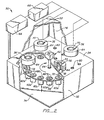
- a multiple assay machine 50 comprises an enclosure 52 having a partition 54 which supports a plurality of receptacles 56.
- a carousel 58 mounted within the enclosure 52 carries a plurality of reservoirs 60.
- An actuator 62 is provided for manipulating the carousel 58 so that various of the reservoirs 60 may be brought into fluid communication with the receptacles 56, as described hereinafter.
- a multiple-head detector 64, a pressure controller 66 and a controller 68 complete the necessary components which comprise the multiple assay machine 50.
- Each receptacle 56 includes an upper chamber 70 and an inlet tube 72 which projects downward into the vicinity of the reservoirs 60.
- the enclosure 52 includes a lower plenum 74 which receives the reservoirs 60, and an upper plenum 76 which receives the upper chambers 70 of the receptacles 56.
- the plenums 74 and 76 are typically in fluid communication (defined by holes 80 in partition 54) so that the pressure in each is equilibrated.
- a portion of the partition 54 adjacent each of the receptacles 56 will define a shield 81 to isolate the multiple head detector 64.
- the multiple head detector 64 will, of course, depend on the nature of the label to be detected. In general, however, its is desirable that the multiple head detector be compact so that its physical placement within the assay machine 50 is straightforward and interferes little in the operation of the device.
- the detector heads 64 are illustrated adjacent the upper chamber 70 of the receptacles 56. This placement is preferred in the embodiment illustrated since the receptacles 56 remain stationary while the reservoirs 60 are manipulated by the actuator 62.
- An alternate embodiment might employ multiple receptacles 56 in conjunction with one or more fixed reservoirs wherein it would be easier to associate the multiple head detector with the stationary reservoirs.
- the wide variety of constructions which may be desired in particular circumstances makes it impossible to list such constructions exhaustively. It is pointed out only that the present invention is applicable to a wide variety of embodiments and is not limited to the particular embodiment illustrated.
- the actuator 62 comprises a motor 82 and a shaft 84 projecting downward therefrom.
- the carousel 58 is mounted at the lower end of the shaft 84, and the motor 82 may be driven both to rotate the shaft and to reciprocate the shaft upward and downward. In this way, the various reservoirs 60 may be serially brought into contact with the inlet tubes 72 of the receptacles 56.
- the reservoirs 60 might be mounted on a plate capable of motion along each of the three rectangular coordinates. Such a construction would be preferred when a particularly compact construction is required since a high density of reservoirs can be mounted on the plate.
- the actuator for manipulating the plate would be more complex, although well within the state of the art.
- Other mechanisms for manipulating the reservoirs, the receptacles, or both, will occur to those skilled in the art and the present invention is not limited to any particular mechanism.
- each receptacle 56 there are four reservoirs 60a, 60b, 60c and 60d associated with each receptacle 56.
- the additional reservoirs are used to provide additional reagents necessary for a multiple step assay, as described in the Experimental Results.
- the various samples and reagents involved in the particular assay will typically be prepared and loaded into the reservoirs 60 prior to placing the reservoirs in the enclosure 52.
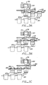
- the reservoirs 60 are then loaded onto the carousel 58 and the carousel is brought into the appropriate position relative to the receptacle 56 with the inlet tube 72 of each receptacle projecting downward into the first reservoir 60a (Figs. 2 and 3A).
- the carousel 58 will be lowered and incrementally rotated until the second reservoir 60b is properly aligned with the entry tube 72.
- the carousel is then raised, immersing the entry tube 72 beneath the surface of the fluid in the second reservoir 60b (Fig. 3B). Similar incrementing is provided to properly position the third reservoir 60c (Fig. 3C) and the fourth reservoir 60d.
- a mechanism for delivering samples, reagents and the like to the reservoirs may be provided so that the reservoirs do not have to be removed from the assay machine 50.
- the structure of such a mechanism would depend on many factors, including the number of reservoirs associated with each receptacle, the nature of the actuator for manipulating the reservoirs, etc.
- the present invention is not limited to the provision of such a mechanism, much less to the particular structure of such a mechanism.
- a blotter 86 may be provided over the opening of each reservoir 60 to clean the outer surface of the inlet tube 72 before or after introduction into the reservoir.
- the blotter 86 will typically be formed from a wicking material and substantially cover the opening of the associated reservoir 60 so that the entry tube 72 will be wiped as it penetrates the blotter.
- Holes 88 must be provided in the blotters 86 to equalize the pressure in the enclosure 52 with that over the surface of the fluid in the reservoir 60.
- the remaining systems of the multiple assay machine 50 are similar to those already described in connection with the single assay machine 10.
- the pressure controller 66 typically a pump, is provided to pressurize the interior of the enclosure 52. If it is desired to pressurize the enclosure with an inert gas, such as helium, a purge and recycling system (not shown) may be provided in connection with the pressure controller 66.
- a controller 68 is provided to coordinate and record the various functions of the multiple assay machine 50. Specifically, the controller 68 will manipulate the actuator 62 in the proper sequence and with the proper timing to carry out the desired assay, control the pressure controller 66 to properly coordinate the manipulation of the fluid level in the various receptacles 56, and communicate with the detectors 64 to record the output as desired.
- the assay machine was generally of the type illustrated in Figs. 1A and 1B, except that it included provisions for holding up to six receptacles and reservoirs simultaneously. Reagents were changed by manually filling the reservoirs at the appropriate point in the assay.
- the receptacles employed in each of the experiments were formed from polypropylene having a chamber volume of 1.5ml and an inlet tube (port) diameter of 1.0mm.
- the antibody solution was then replaced by a wash solution of phosphate buffer (0.05M, pH8.0) containing 0.1g/100ml bovine serum albumin, 0.45g/100ml NaCI, and 0.01g/100ml sodium azide, referred to hereinafter as BSA-buffer.
- BSA-buffer phosphate buffer
- the reservoir containing the BSA-buffer was then pressurized and depressurized five times with a cycle time of 30 seconds in order to wash the interior of the receptacles free of any loosely bound antibody and coat any unreacted surface within the reaction zone to prevent nonspecific binding.
- Three reservoirs were manually filled with 50 ⁇ l of human sera containing thyroxine concentrates of 0, 4 and 20 ⁇ g/100ml, respectively, in 1.15ml of Tris buffered saline with 0.02M sodium azide, 0.4mM ANS, 0.6mM sodium salicylate and about 120,000dpm (disintegrations per minute) of 125 I-labelled thyroxine, and placed in the assay machine.
- the total volume of solution in the reservoirs was 1.2ml and the total amount of radioactivity was about 25,000 counts per two minutes.
- the background radioactivity measured in the presence of the receptacle alone was about 300 counts per two minutes.
- These reagents were obtained from a commercial T4 assay kit (Clinical Assays Corporation, Cat. No. Ca-535).
- An activated receptacle was placed in each reservoir and the reservoirs were pressurized to 2.26x10 5 Pa (18 psig) for five minutes in order to drive about 900 ⁇ l of the solution into the receptacle and cover the surface of the activated solid phase.
- the pressure was released back to atmospheric and the solution allowed to drain away from the activated solid phase.
- the radioactivity bound to the interior of the receptacle was then measured for two minutes, before again repressurizing the reservoir to reintroduce the solution into the receptacle.
- the cycle was repeated every five minutes (i.e., pressurized for three minutes and measure for two minutes) for a total of ten measurements after 50 minutes.
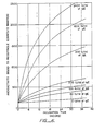
- Fig. 4 the amounts of radioactivity bound to the reactive solid phases of the three individual receptacles are plotted against time. The slopes of these lines, as well as the predicted end-points, are inversely related to the amounts of non-radioactive T4 in the sample solutions.
- Curve A shows the rapid increase with time of the amount of radioactive T4 bound to the solid-phase in the presence of 50 ⁇ l of human serum containing no detectable non-radioactive T4.
- Curves B and C show the decrease in bound radioactivity when the human serum contained, respectively, 4pg/100ml and 20pg/100ml of added non-radioactive thyroxine.
- the remaining three receptacles were also exposed for 30 minutes, 6 hours and 24 hours, respectively, during which time the assay machine was depressurized and repressurized every 10 minutes so that the solution drained out of each receptacle to effect agitation.
- the solutions of diluted human sera was manually replaced in the reservoirs by solutions containing approximately 120,000dpm of an 125 1-labelled monoclonal antibody to hepatitis B antigen having an approximate specific activity of 8 to 14 ⁇ C/ ⁇ g.
- the reservoirs were then pressurized to 2.26x10 5 (18psig) to drive this new solution into the receptacles and allow it to react with any hepatitits antigen bound to the solid-phase reactant. After 10 minutes the pressure was released and the solution drained away from the activated solid phase. The radioactivity remaining bound to the interior of the receptacle was then measured for two minutes, before again repressurizing the reservoir to continue the reaction of the solution with the solid-phase. Measurements were taken every 12 minutes for a total of 24 hours.
- curves show the successive increase with time in the amount of radioactivity bound to the receptacle during Reaction Two, in the presence of the previously insolubilized hepatitis B antigen.
- Curves A, B and C represent the assays where Reaction One was performed with agitation, while curves A', B' and C' represent the assay carried out over the same duration, but without agitation.
- the total amount of radioactivity was about 24,000 counts per two minutes.
- the present invention provides a method for significantly decreasing the time required to perform standard assays by decreasing the time required to approach equilibrium.
- the receptacle was activated with a fluorescent- labeled monoclonal anti-IgE immunoglobulin preparation, bound to the wall by reaction with an antibody directed against the fluorescent group. Both of these reagents were provided by Hybritech Incorporated. The non-fluorescent antibody was bound to the wall of the receptacle using the technique of Example A.
- the assay reaction can be carried out in a single incubation.
- the reaction mixture contained 50 ⁇ l of a standard solution of IgE in human serum, 200 ⁇ l (about 25,000 counts per two minutes) of 1251-labeled anti-IgE and 1000pi of BSA-buffer. Except for the BSA-buffer, all of these reagents are part of a commercial Tandem@ IgE assay kit (Cat. #3053, Lot#J1007) provided by Hybritech Incorporated.
- the assay was performed over 36 hours in the same manner as Reaction Two of Example B. Seven assays were performed with differing known concentrations of IgE (0 to 24001U/ml). The total volume of solution in each reservoir was 1.2ml.
- Fig. 6 the amounts of radioactivity bound to the reactive solid phases of seven individual receptacles are plotted against time.
- the results demonstrate a successive increase in radioactivity with time when antigen is present and shown that by extrapolating each curve it is possible to predict the respective end-point radioactivities.
- the slopes of the lines, as well as their predicted end-points, are seen to be directly related to the amounts of non-radioactive (standard) IgE antigen in the solutions being assayed.
- the method and apparatus of the present invention provide for relatively rapid assays achieved by periodic agitation of the sample solutions under pressure. Moreover, the ability to separate free from bound label allows the performance of rate mode or dynamic assays where the progress of the assay reaction can be observed over time.
Landscapes
- Health & Medical Sciences (AREA)
- Immunology (AREA)
- Life Sciences & Earth Sciences (AREA)
- Chemical & Material Sciences (AREA)
- Engineering & Computer Science (AREA)
- Pathology (AREA)
- General Physics & Mathematics (AREA)
- General Health & Medical Sciences (AREA)
- Biochemistry (AREA)
- Analytical Chemistry (AREA)
- Physics & Mathematics (AREA)
- Urology & Nephrology (AREA)
- Molecular Biology (AREA)
- Hematology (AREA)
- Biomedical Technology (AREA)
- Food Science & Technology (AREA)
- Medicinal Chemistry (AREA)
- Microbiology (AREA)
- Cell Biology (AREA)
- Biotechnology (AREA)
- Automatic Analysis And Handling Materials Therefor (AREA)
- Investigating Or Analysing Biological Materials (AREA)
- Analysing Materials By The Use Of Radiation (AREA)
Claims (39)
caractérisé en ce que:
et où le procédé comprend l'étape de détecter la présence de l'analyte en déterminant la quantité du marqueur dans la zone réactionnelle (18, 24) ou le réservoir (22, 60).
caractérisé en ce que les réservoirs (22, 60) sont placés dans une enceinte (28, 52);
Applications Claiming Priority (2)
| Application Number | Priority Date | Filing Date | Title |
|---|---|---|---|
| US354848 | 1982-03-04 | ||
| US06/354,848 US4477578A (en) | 1982-03-04 | 1982-03-04 | Method and apparatus for performing assays |
Publications (3)
| Publication Number | Publication Date |
|---|---|
| EP0103622A1 EP0103622A1 (fr) | 1984-03-28 |
| EP0103622A4 EP0103622A4 (fr) | 1984-07-26 |
| EP0103622B1 true EP0103622B1 (fr) | 1987-09-23 |
Family
ID=23395153
Family Applications (1)
| Application Number | Title | Priority Date | Filing Date |
|---|---|---|---|
| EP83901134A Expired EP0103622B1 (fr) | 1982-03-04 | 1983-02-22 | Procede et dispositif pour l'execution d'analyses |
Country Status (6)
| Country | Link |
|---|---|
| US (1) | US4477578A (fr) |
| EP (1) | EP0103622B1 (fr) |
| JP (1) | JPS59500333A (fr) |
| AU (1) | AU556394B2 (fr) |
| DE (1) | DE3373841D1 (fr) |
| WO (1) | WO1983003140A1 (fr) |
Families Citing this family (46)
| Publication number | Priority date | Publication date | Assignee | Title |
|---|---|---|---|---|
| US4775635A (en) * | 1985-04-12 | 1988-10-04 | E. I. Du Pont De Nemours And Company | Rapid assay processor |
| US4753775A (en) * | 1985-04-12 | 1988-06-28 | E. I. Du Pont De Nemours And Company | Rapid assay processor |
| US4806313A (en) * | 1985-04-12 | 1989-02-21 | E. I. Du Pont De Nemours And Company | Rapid assay processor |
| US4701304A (en) * | 1985-04-19 | 1987-10-20 | Applied Protein Technologies, Inc. | Apparatus for automated synthesis of peptides |
| US5120504A (en) * | 1986-07-14 | 1992-06-09 | Hybritech Incorporated | Apparatus for immunoassays with vent chennels in the container side wall |
| GB8707299D0 (en) * | 1987-03-26 | 1987-04-29 | Secr Social Service Brit | Assay apparatus |
| US4855110A (en) * | 1987-05-06 | 1989-08-08 | Abbott Laboratories | Sample ring for clinical analyzer network |
| USD319103S (en) | 1988-06-20 | 1991-08-13 | Chiu John F | Immunoassay test unit kit or the like |
| US5030561A (en) * | 1988-12-27 | 1991-07-09 | Becton, Dickinson And Company | Chlamydia assay using amidine modified supports or particles |
| US5079170A (en) * | 1989-05-18 | 1992-01-07 | Quidel Corporation | Method of sample transfer using a filter applicator |
| DE69024364T2 (de) * | 1989-10-17 | 1996-07-11 | British Tech Group | Verstärkter chemilumineszenzassay |
| DE69031334T2 (de) * | 1989-12-22 | 1998-01-29 | Alfa Biotech S.P.A., Pomezia, Rom/Roma | Vorrichtung zum selektiven Rühren von Reaktionskomponenten |
| CA2007620A1 (fr) * | 1990-02-11 | 1991-07-11 | Charles Terrence Macartney | Tube pour la collecte d'echantillons biologiques |
| TW199858B (fr) * | 1990-03-30 | 1993-02-11 | Fujirebio Kk | |
| US5559032A (en) * | 1990-06-29 | 1996-09-24 | Pomeroy; Patrick C. | Method and apparatus for post-transfer assaying of material on solid support |
| US5198340A (en) * | 1991-01-17 | 1993-03-30 | Genentech, Inc. | Assay for free igf-i, igf-ii, and gh levels in body fluids |
| US6436349B1 (en) | 1991-03-04 | 2002-08-20 | Bayer Corporation | Fluid handling apparatus for an automated analyzer |
| US6498037B1 (en) | 1991-03-04 | 2002-12-24 | Bayer Corporation | Method of handling reagents in a random access protocol |
| CA2384535C (fr) * | 1991-03-04 | 2006-08-15 | Bayer Corporation | Analyseur automatise |
| US5565173A (en) * | 1992-10-08 | 1996-10-15 | Warner-Lambert Company | Apparatus and method for multiple simultaneous synthesis |
| US5702672A (en) * | 1992-10-08 | 1997-12-30 | Warner-Lambert Company | Apparatus and method for multiple simultaneous synthesis |
| US5324483B1 (en) * | 1992-10-08 | 1996-09-24 | Warner Lambert Co | Apparatus for multiple simultaneous synthesis |
| JPH09500826A (ja) * | 1993-07-30 | 1997-01-28 | イー・アイ・デユポン・ドウ・ヌムール・アンド・カンパニー | 向流多相液体分離のための装置 |
| US5591335A (en) * | 1995-05-02 | 1997-01-07 | Memtec America Corporation | Filter cartridges having nonwoven melt blown filtration media with integral co-located support and filtration |
| US5609822A (en) * | 1995-07-07 | 1997-03-11 | Ciba Corning Diagnostics Corp. | Reagent handling system and reagent pack for use therein |
| US6066300A (en) * | 1995-07-07 | 2000-05-23 | Bayer Corporation | Reagent handling system and configurable vial carrier for use therein |
| US5750881A (en) * | 1995-07-13 | 1998-05-12 | Chiron Diagnostics Corporation | Method and apparatus for aspirating and dispensing sample fluids |
| US5641006A (en) * | 1995-07-13 | 1997-06-24 | Chiron Diagnostics Corporation | Liquid supply apparatus and method of operation |
| US6158269A (en) * | 1995-07-13 | 2000-12-12 | Bayer Corporation | Method and apparatus for aspirating and dispensing sample fluids |
| US5856194A (en) | 1996-09-19 | 1999-01-05 | Abbott Laboratories | Method for determination of item of interest in a sample |
| US5795784A (en) | 1996-09-19 | 1998-08-18 | Abbott Laboratories | Method of performing a process for determining an item of interest in a sample |
| US6077713A (en) * | 1998-06-30 | 2000-06-20 | Dade Behring Inc. | Method and apparatus for extracting liquid samples from a closed container |
| US6461812B2 (en) | 1998-09-09 | 2002-10-08 | Agilent Technologies, Inc. | Method and multiple reservoir apparatus for fabrication of biomolecular arrays |
| JP3429282B2 (ja) * | 2001-02-02 | 2003-07-22 | リサーチ・インターナショナル・インコーポレーテッド | 自動化されたシステム、及びサンプルの分析方法 |
| EP2311934B1 (fr) | 2001-09-06 | 2013-06-05 | Rapid Micro Biosystems, Inc. | Détection rapide de cellules proliférantes |
| US20050221281A1 (en) * | 2003-01-08 | 2005-10-06 | Ho Winston Z | Self-contained microfluidic biochip and apparatus |
| US7496245B2 (en) * | 2004-08-20 | 2009-02-24 | Research International, Inc. | Misalignment compensating optical sensor and method |
| CN101528912B (zh) * | 2005-09-26 | 2014-08-27 | 快速微型生物系统公司 | 包含生长培养基的盒 |
| US7651869B2 (en) * | 2006-03-14 | 2010-01-26 | Research International, Inc. | Optical assay apparatus and methods |
| CN102224260B (zh) | 2008-09-24 | 2015-11-25 | 施特劳斯控股公司 | 用于检测分析物的试剂盒和装置 |
| MX368123B (es) | 2011-11-07 | 2019-09-19 | Rapid Micro Biosystems Inc | Cassette para pruebas de esterilidad. |
| IN2014DN08564A (fr) | 2012-04-16 | 2015-05-22 | Rapid Micro Biosystems Inc | |
| GB2532213A (en) * | 2014-11-11 | 2016-05-18 | Stratec Biomedical Ag | Device for continuously supplying a liquid to an analyser system |
| DE102017116760B3 (de) * | 2017-07-25 | 2018-12-27 | Thomas Märsch | Vorrichtung zum Aufbereiten einer Gewebeprobe und insbesondere zum Herstellen eines eine Gewebeprobe enthaltenden Wachsblocks |
| CA3097748A1 (fr) | 2018-04-19 | 2019-10-24 | First Light Biosciences, Inc. | Detection d'anticorps |
| WO2020073015A1 (fr) | 2018-10-04 | 2020-04-09 | First Light Diagnostics, Inc. | Instrument d'analyse |
Family Cites Families (21)
| Publication number | Priority date | Publication date | Assignee | Title |
|---|---|---|---|---|
| US2692209A (en) * | 1953-04-29 | 1954-10-19 | Gen Electric | Bulb coating process |
| CA990416A (en) * | 1972-04-19 | 1976-06-01 | Sieuwko J. Mantel | Device suitable for use in radioimmunoassay and method of determining the content of a specific hormone in a serum sample |
| US3356096A (en) * | 1965-12-22 | 1967-12-05 | Lerner Lab Inc | Automatic immersion apparatus |
| US3469438A (en) * | 1967-04-12 | 1969-09-30 | Perkin Elmer Corp | Automatically controlled multiple sampling measurement system |
| US3723066A (en) * | 1968-06-14 | 1973-03-27 | Hycel Inc | Reagent dispensing means for chemical testing apparatus |
| US3684448A (en) * | 1969-06-30 | 1972-08-15 | Boehringer Sohn Ingelheim | Apparatus and process of in vitro determination of the dissolution behavior of drugs or pharmaceutical compositions containing the same in the gastrointestinal tract |
| US3768978A (en) * | 1971-03-01 | 1973-10-30 | Hamilton Co | Disposable pipette |
| US3837376A (en) * | 1971-06-01 | 1974-09-24 | Metropolitan Pathology Labor I | Blood serum collection tube and method |
| US3826621A (en) * | 1972-05-01 | 1974-07-30 | Micromedic Systems Inc | Apparatus for transferring a liquid from one container to another |
| US3850136A (en) * | 1972-05-24 | 1974-11-26 | Gen Electric | Positive pressure coating device |
| US3846077A (en) * | 1972-09-18 | 1974-11-05 | P Ohringer | Liquid sample collection tube |
| CA1054050A (fr) * | 1973-05-01 | 1979-05-08 | Wisconsin Alumni Research Foundation | Colonne de gel utilisee dans la purification de sang et les dosages immunologiques |
| FI55093C (fi) * | 1974-07-05 | 1979-05-10 | Osmo Antero Suovaniemi | Foerfarande foer exakt maetning av absorption av smao vaetskemaengder samt anordning foer dess genomfoerande |
| DE2408543A1 (de) * | 1974-02-22 | 1975-08-28 | Osmo Antero Suovaniemi | Analysator |
| US4081246A (en) * | 1976-05-03 | 1978-03-28 | Beckman Instruments, Inc. | Solid phase column immunoassay procedure employing novel immunochemical composites |
| US4225784A (en) * | 1976-06-17 | 1980-09-30 | Smith Kline Instruments, Inc. | Covalently bound biological substances to plastic materials and use in radioassay |
| US4087248A (en) * | 1976-07-26 | 1978-05-02 | Miles Laughton E | Multiple assay machine and method |
| US4210418A (en) * | 1976-08-30 | 1980-07-01 | Mallinckrodt, Inc. | Container for immunochemical and enzymatical determinations or procedures |
| US4117728A (en) * | 1977-12-22 | 1978-10-03 | Miles Laboratories, Inc. | Pipette |
| JPS608745B2 (ja) * | 1978-02-14 | 1985-03-05 | 三洋化成工業株式会社 | 免疫活性物質−つや消しガラス複合体,その製造法及び該複合体を含有してなる測定試薬 |
| US4277950A (en) * | 1980-02-29 | 1981-07-14 | Union Carbide Corporation | Cryogenic liquid transfer termination apparatus |
-
1982
- 1982-03-04 US US06/354,848 patent/US4477578A/en not_active Expired - Lifetime
-
1983
- 1983-02-22 WO PCT/US1983/000239 patent/WO1983003140A1/fr not_active Ceased
- 1983-02-22 AU AU13777/83A patent/AU556394B2/en not_active Ceased
- 1983-02-22 JP JP58501158A patent/JPS59500333A/ja active Pending
- 1983-02-22 EP EP83901134A patent/EP0103622B1/fr not_active Expired
- 1983-02-22 DE DE8383901134T patent/DE3373841D1/de not_active Expired
Also Published As
| Publication number | Publication date |
|---|---|
| AU556394B2 (en) | 1986-10-30 |
| EP0103622A1 (fr) | 1984-03-28 |
| DE3373841D1 (en) | 1987-10-29 |
| AU1377783A (en) | 1983-10-18 |
| WO1983003140A1 (fr) | 1983-09-15 |
| EP0103622A4 (fr) | 1984-07-26 |
| JPS59500333A (ja) | 1984-03-01 |
| US4477578A (en) | 1984-10-16 |
Similar Documents
| Publication | Publication Date | Title |
|---|---|---|
| EP0103622B1 (fr) | Procede et dispositif pour l'execution d'analyses | |
| US4087248A (en) | Multiple assay machine and method | |
| US4425438A (en) | Assay method and device | |
| US4517288A (en) | Solid phase system for ligand assay | |
| US4918025A (en) | Self contained immunoassay element | |
| US4816418A (en) | Method and apparatus for performing automated, multi-sequential immunoassays | |
| RU2102758C1 (ru) | Устройства для автоматического проведения иммуноанализа за несколько последовательных этапов по меньшей мере одного биологического вещества из множества биологических образцов, способ и реактив для применения указанных устройств | |
| US5073484A (en) | Quantitative analysis apparatus and method | |
| US4197287A (en) | Method and apparatus for performing in nitro clinical diagnostic tests using a solid phase assay system having special utility for use with automatic pipetting equipment | |
| JP3521144B2 (ja) | 自動連続ランダム・アクセス分析システムおよびその構成要素 | |
| CN103430024B (zh) | 用于免疫分析检测的系统 | |
| NZ201901A (en) | An apparatus suitable for performing automated heterogeneous immunoassays in a plurality of samples | |
| JPH11316226A (ja) | 自動測定用カートリッジ及び自動測定法 | |
| JPS63281053A (ja) | カートリッジ及び固相免疫検定を行うための方法 | |
| JPH0222560A (ja) | 逐次分析試験を行なうための反応容器 | |
| US4774174A (en) | Solid phase system for ligand assay | |
| US20020025583A1 (en) | Analytical rotor and method for detecting analytes in liquid samples | |
| US4786606A (en) | Solid phase system for ligand assay | |
| KR20200102033A (ko) | 입자와 용액의 동시 이동에 의한 분석물질을 검출하는 장치 및 이를 이용한 검출방법 | |
| US7381374B2 (en) | Immunoassay devices and methods of using same | |
| JP3010509B2 (ja) | 免疫測定用容器、免疫測定方法及び免疫測定装置 | |
| JPH0655084A (ja) | 免疫測定用反応容器 | |
| US8501496B2 (en) | Immunoassay cuvettes | |
| JPS628749B2 (fr) | ||
| GB1601242A (en) | Multiple assay machine and method |
Legal Events
| Date | Code | Title | Description |
|---|---|---|---|
| PUAI | Public reference made under article 153(3) epc to a published international application that has entered the european phase |
Free format text: ORIGINAL CODE: 0009012 |
|
| AK | Designated contracting states |
Designated state(s): DE FR GB |
|
| 17P | Request for examination filed |
Effective date: 19840313 |
|
| RBV | Designated contracting states (corrected) |
Designated state(s): DE GB |
|
| 17Q | First examination report despatched |
Effective date: 19860121 |
|
| GRAA | (expected) grant |
Free format text: ORIGINAL CODE: 0009210 |
|
| AK | Designated contracting states |
Kind code of ref document: B1 Designated state(s): DE GB |
|
| REF | Corresponds to: |
Ref document number: 3373841 Country of ref document: DE Date of ref document: 19871029 |
|
| PLBE | No opposition filed within time limit |
Free format text: ORIGINAL CODE: 0009261 |
|
| STAA | Information on the status of an ep patent application or granted ep patent |
Free format text: STATUS: NO OPPOSITION FILED WITHIN TIME LIMIT |
|
| 26N | No opposition filed | ||
| REG | Reference to a national code |
Ref country code: GB Ref legal event code: 732 |
|
| PGFP | Annual fee paid to national office [announced via postgrant information from national office to epo] |
Ref country code: GB Payment date: 19920115 Year of fee payment: 10 |
|
| PGFP | Annual fee paid to national office [announced via postgrant information from national office to epo] |
Ref country code: DE Payment date: 19920120 Year of fee payment: 10 |
|
| PG25 | Lapsed in a contracting state [announced via postgrant information from national office to epo] |
Ref country code: GB Effective date: 19930222 |
|
| GBPC | Gb: european patent ceased through non-payment of renewal fee |
Effective date: 19930222 |
|
| PG25 | Lapsed in a contracting state [announced via postgrant information from national office to epo] |
Ref country code: DE Effective date: 19940503 |