EP0103780A1 - Marque souterraine, son procédé de fabrication et procédé pour l'introduire dans la terre - Google Patents
Marque souterraine, son procédé de fabrication et procédé pour l'introduire dans la terre Download PDFInfo
- Publication number
- EP0103780A1 EP0103780A1 EP83108416A EP83108416A EP0103780A1 EP 0103780 A1 EP0103780 A1 EP 0103780A1 EP 83108416 A EP83108416 A EP 83108416A EP 83108416 A EP83108416 A EP 83108416A EP 0103780 A1 EP0103780 A1 EP 0103780A1
- Authority
- EP
- European Patent Office
- Prior art keywords
- underfloor
- housing
- ferrite core
- coil
- capacitor
- Prior art date
- Legal status (The legal status is an assumption and is not a legal conclusion. Google has not performed a legal analysis and makes no representation as to the accuracy of the status listed.)
- Granted
Links
Images

Classifications
-
- G—PHYSICS
- G01—MEASURING; TESTING
- G01C—MEASURING DISTANCES, LEVELS OR BEARINGS; SURVEYING; NAVIGATION; GYROSCOPIC INSTRUMENTS; PHOTOGRAMMETRY OR VIDEOGRAMMETRY
- G01C15/00—Surveying instruments or accessories not provided for in groups G01C1/00 - G01C13/00
- G01C15/02—Means for marking measuring points
- G01C15/04—Permanent marks; Boundary markers
Definitions
- the invention relates to an underfloor mark to facilitate the location and determination of locations and objects located below the surface, in particular for geodetic purposes, with a housing consisting of a non-magnetic material and an oscillating circuit located therein made of a metallic core, a coil located thereon and a capacitor electrically connected to it.
- the invention further relates to a method for producing this underfloor mark.
- the invention also relates to a method for introducing this underfloor mark into the ground.
- boundary stone In geodesy, in land surveying and in other areas, the task is to pinpoint a location and make that location retrievable.
- a boundary stone can also be implemented very deliberately. In order to be able to find the surveyed places anyway, one has already begun to bring an object into the ground under the boundary stone or in a very specific position, for example to push it into the ground to a certain depth. This item can then only be found by digging. This is a very tedious, time-consuming and often unsuccessful job.
- identification tags have been built which the skiers carry on their bodies (DE-AS 1 473 763).
- This identification tag is essentially a large frame coil embedded in plastic. This forms a passive resonant circuit. When targeting the frame coil with a transmitter, this energy is extracted. A negative amplitude arises. From this one can infer the position of and the distance to the frame coil and thus to the spilled person.
- a method for locating buried subjects DE-PS 1 249 416
- a transmitter is operated in a specific manner and is used to target an electromagnetic oscillating circuit carried by the buried person and to induce natural vibrations. The transmitter is switched off periodically. The vibrations emitted by the vibrating circuit carried by the spilled person are measured in the transmission pauses.
- the invention has for its object to provide a so-called underfloor mark, which is introduced under a boundary stone or in a specific position to this or instead of the boundary stone in the ground instead of the simple objects mentioned above and which then as a so-called passive resonant circuit with a special trained transmitter or radio measuring device, hereinafter referred to as detector, can be located.
- a so-called underfloor mark could therefore be recognized from the earth's surface without a trench and its position precisely determined.
- the underfloor mark should also be able to be installed in the floor of a factory or warehouse or in a driveway. Here it is used for automatic guidance or steering of vehicles.
- the underfloor marks are laid along a path to be driven by the vehicles. There is a transmitter in the vehicle that recognizes the underfloor marks.
- the invention provides, using the features mentioned at the outset and belonging to the general prior art, that the core is a rod-shaped ferrite core, a spacer made of a non-magnetic material is attached to one end of the ferrite core and the capacitor is in turn open the end of the spacer facing away from the ferrite core is attached.
- the core is a rod-shaped ferrite core
- a spacer made of a non-magnetic material is attached to one end of the ferrite core and the capacitor is in turn open the end of the spacer facing away from the ferrite core is attached.
- the resonant circuit has a low-loss coil and that it can be easily and precisely tuned to a target frequency.
- the ferrite core proposed according to the invention has very low losses and he further enables a sharp adjustment of the natural frequency.
- the coil is self-supporting and sits firmly on the ferrite core.
- Such a coil has no core leading to losses.
- the individual turns are connected to one another, for example, by a varnish or a synthetic resin.
- Such a coil can also be easily pushed back and forth on the ferrite core.
- a ferrite core is almost never homogeneous.
- the natural frequency of the resonant circuit can be influenced by moving the coil.
- the capacitor is held at a distance from the ferrite core by the spacer. This spacing keeps the coil from being damped by the capacitor.
- the ferrite core with the coil sitting on it and the capacitor attached to one of its ends is a narrow structure.
- the housing in which the ferrite core is only accommodated for mechanical protection can thus be kept narrow.
- the coil is fixed on the ferrite core with a quick contact adhesive.
- the resonant circuit is switched on to a frequency generator for adjustment and the coil is then moved back and forth on the ferrite core.
- the target frequency is reached at a certain position of the coil, it is fixed in it with the quick-contact adhesive on the ferrite core.
- a metallic short-circuit ring which is arranged on the housing is provided for this purpose.
- This short-circuit ring dampens the resonant circuit and thus changes its natural frequency. To change this frequency, it is pushed back and forth a little and then fixed in a certain position.
- the housing has an external thread and the short-circuit ring has an internal thread and the short-circuit ring can be screwed onto the housing.
- the ferrite core has a threaded bore at one end and a ferrite rod can be screwed into it. By screwing the ferrite rod back and forth, the length and thus the inductance of the ferrite core are changed.
- the ferrite core with the coil and the capacitor is inserted into a housing.
- This is expediently injection molded from a tough plastic.
- the cavity of the housing which receives the ferrite core, the coil, the spacer and the capacitor is filled with elastic synthetic resin. This stabilizes the whole thing mechanically and also electrically. The penetration of moisture and dirt is also prevented.
- an elastic synthetic resin is used. This mitigates or completely eliminates the effects of knocks and bumps on the core, coil and capacitor.
- the ferrite core can also be fixed in a practical embodiment by rubber rings placed on its ends in the housing. In this case it is advisable to close the upper open end of the housing with a plug.
- the housing itself has the shape of a hollow cylinder with a cone placed on its lower end.
- a housing can be easily manufactured and, with the tip of the cone, inserted easily and with little effort into the soil to the desired depth.
- the ferrite core must be of different lengths.
- the production of ferrite cores of different lengths presents no particular difficulties. This is different with the housing molded from a plastic. An injection mold is very complex and therefore also expensive.
- an extension sleeve is inserted into the open end of the housing and the ferrite core is extended into the area of the extension sleeve.
- the extension sleeve is expediently glued into the housing. The extension sleeve thus enables the housing to be produced in one length with a single injection mold and, if necessary, extended with an extension sleeve.
- the cone has a larger diameter than the housing at its upper, larger-diameter end to form a stepped shoulder. Devices or tools can be placed on this section from above to push the housing into the ground.
- the housing distributes rip on its outside over its circumference pen.
- the housing is mechanically fixed by these ribs.
- Another measure according to the invention serves the same purpose, according to which the ribs and / or the housing are colored the same and / or differently.
- the spacer is attached to one end of the ferrite core and the capacitor on the free end of the spacer with a contact adhesive, the coil electrically connected to the capacitor is placed on the ferrite core and moved to a position in which oscillating circuit consisting of coil and capacitor vibrates to the desired frequency, the coil is fixed in this position with a quick-contact adhesive, the whole is inserted into a housing and the cavity of the housing is then poured out.
- Another possibility according to the invention is characterized in that the spacer is fastened on one end of the ferrite core and the capacitor on the free end of the spacer with a contact adhesive, the coil electrically connected to the capacitor is placed on the ferrite core and shifted into one position, in which the resonant circuit consisting of coil and capacitor vibrates to the desired frequency, the coil is fixed in this position with a quick-contact adhesive and the whole is then encapsulated.
- the housing is not required as a special component.
- a synthetic resin compound or the like is sprayed on in such a way that it simulates the housing. This process creates a mechanically particularly strong underfloor mark. The costs for the injection mold and the molding compound are however high.
- a third possibility according to the invention is characterized in that the spacer is fastened on one end of the ferrite core and the capacitor on the free end of the spacer with a contact adhesive, the coil electrically connected to the capacitor is placed on the ferrite core and moved into one position, in which the resonant circuit consisting of the coil and capacitor oscillates to the set frequency, the coil is fixed in this position with a quick-contact adhesive, the whole is inserted into a housing, the ferrite core is fixed in the housing with rubber rings pushed onto it, this is closed with a stopper and this is closed an adhesive or ultrasound is welded on watertight.
- the invention proposes that a drive tube is pushed onto the housing, possibly with a clamp, until it is seated on the step-shaped heel, the underfloor mark then pushed or struck into the ground with the drive tube to the desired depth, and the underfloor mark then is pushed out of the system with the drive tube with a stick.
- FIG. 1 shows the cylindrical housing 12.
- the cone 14 is attached in one piece to its lower end.
- the ferrite core 16 is located in the housing 12.
- the self-supporting coil 18 sits on this.
- the spacer 20 is placed on the lower end of the ferrite core 16 and the capacitor 22 is placed on its lower end, if appropriate glued.
- the coil 18 and the capacitor 22 are electrically connected to one another, which is not shown in detail.
- the cavity of the housing 12 is potted with a synthetic resin.
- the ferrite core 16, the coil 18, the spacer 20 and the capacitor 22 are sealed enclosed.
- the ferrite core 16 with the parts attached to it are fixed in the housing by rubber rings 24. In this case, the housing 12 is closed with a plug 26.
- the housing has 12 ribs 28 on its outside. These can have the semicircular cross-section shown in the top view or else another shape. They can also be larger than shown.
- the cone 14 projects radially beyond the housing 12. This results in the stepped shoulder 30.
- FIG. 1 also shows the short-circuit ring 36 screwed onto the housing 12. It can be screwed on and off. In the position in which the resonant circuit vibrates at the desired frequency, the short-circuit ring 36 is fixed. The illustration according to FIG. 1 is further explained in FIGS. 2 and 3.
- the lower end of the drive tube 32 stands on the shoulder 30.
- the underfloor mark is pressed or hammered into the ground with this drive tube 32.
- the drive tube 32 can rest on the ribs 28 with some clamping. If the drive tube cannot then be easily pulled off the ribs, the underfloor mark can be pushed out of the drive tube 32 with a stick. The underfloor mark is then free in the ground. Her interior is protected by the ribs 28. If the underfloor mark is touched with a spade or any tool, the ribs 28 can deform without damaging the electrical parts. If the ground is very hard or stony, a hole can be made or drilled before the underfloor mark is inserted.
- the underfloor mark can also be embedded in the ground using the well-known horsetail principle. Here, several tubes are telescoped. This pushes the underfloor mark into the ground.
- FIG. 6 shows the embodiment of the ferrite core 16 in which two disks 34 are arranged on the ferrite core 16 at a mutual spacing. Between these disks 34, the coil 18 is wound turn by turn onto the ferrite core 16. 6 further shows a ferrite rod 38. This is screwed into a threaded bore at one end of the ferrite core 16. By screwing the ferrite rod 38 on and off, the length and thus the inductance of the ferrite core 16 are changed. The natural frequency of the resonant circuit can also be set in this way.
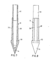
- FIG. 7 shows that a ferrite core 16 to be inserted into this extended housing is considerably longer than that according to FIG. 1. To simplify the illustration and to avoid repetitions, the ferrite core 16, the coil 18, etc. are not shown in FIG. 7.
- An underfloor mark lying in the ground can be located using a radio measuring device, generally called a detector.
- a detector detects an underfloor mark with its radiation area, its vibration amplitude changes.
- detectors on the market in which the type of change in amplitude can be used to determine the exact distance to and therefore the position of the underfloor mark.
- These measurements are made very easy with the underfloor mark according to the invention which is precisely matched to the desired frequency.
- the underfloor mark is embedded in the ground instead of or near boundary stones. But it can also be used to mark pipe and cable routes will. It can also be used to locate spilled material if it is in a non-magnetic medium.
Landscapes
- Physics & Mathematics (AREA)
- Engineering & Computer Science (AREA)
- General Physics & Mathematics (AREA)
- Radar, Positioning & Navigation (AREA)
- Remote Sensing (AREA)
- Geophysics And Detection Of Objects (AREA)
- Underground Or Underwater Handling Of Building Materials (AREA)
Priority Applications (1)
| Application Number | Priority Date | Filing Date | Title |
|---|---|---|---|
| AT83108416T ATE29067T1 (de) | 1982-08-27 | 1983-08-26 | Unterflurmarke, verfahren zu deren herstellung und verfahren zu deren einbringung in das erdreich. |
Applications Claiming Priority (2)
| Application Number | Priority Date | Filing Date | Title |
|---|---|---|---|
| DE3231870 | 1982-08-27 | ||
| DE3231870A DE3231870C2 (de) | 1982-08-27 | 1982-08-27 | Unterflurmarke, Verfahren zu deren Herstellung und Verfahren zu deren Einbringung in das Erdreich |
Publications (2)
| Publication Number | Publication Date |
|---|---|
| EP0103780A1 true EP0103780A1 (fr) | 1984-03-28 |
| EP0103780B1 EP0103780B1 (fr) | 1987-08-19 |
Family
ID=6171822
Family Applications (1)
| Application Number | Title | Priority Date | Filing Date |
|---|---|---|---|
| EP83108416A Expired EP0103780B1 (fr) | 1982-08-27 | 1983-08-26 | Marque souterraine, son procédé de fabrication et procédé pour l'introduire dans la terre |
Country Status (4)
| Country | Link |
|---|---|
| EP (1) | EP0103780B1 (fr) |
| AT (1) | ATE29067T1 (fr) |
| DE (2) | DE3231870C2 (fr) |
| WO (1) | WO1984001025A1 (fr) |
Cited By (2)
| Publication number | Priority date | Publication date | Assignee | Title |
|---|---|---|---|---|
| FR2669727A1 (fr) * | 1990-11-23 | 1992-05-29 | Lebec Sa E Lts | Dispositif de bornage a usage topographique. |
| EP1916501A3 (fr) * | 2006-10-25 | 2010-01-27 | Jean-Edouard Gissinger | Borne topographique |
Families Citing this family (3)
| Publication number | Priority date | Publication date | Assignee | Title |
|---|---|---|---|---|
| DK266284D0 (da) * | 1984-05-30 | 1984-05-30 | Willy Palle Pedersen | Fixpunktmarkeringsindretning |
| DK202090D0 (da) * | 1990-08-23 | 1990-08-23 | Willy Palle Pedersen | Markoer af elektromagnetisk resonanstype |
| DE20204704U1 (de) | 2002-03-24 | 2002-07-25 | Krämer, Albert, Dipl.-Ing. (FH), 92559 Winklarn | Markierungsstein mit Metalleinlage |
Citations (3)
| Publication number | Priority date | Publication date | Assignee | Title |
|---|---|---|---|---|
| DE855724C (de) * | 1951-02-09 | 1952-11-17 | Walter Brockmann | Vorrichtung zum Eintreiben von Markierungspfaehlen |
| US3836842A (en) * | 1973-01-22 | 1974-09-17 | Bell Canada Northern Electric | Encapsulated electrically resonant circuit and interrogating apparatus and method for finding same in various locations |
| WO1983001306A1 (fr) * | 1981-10-08 | 1983-04-14 | Willy Petersen | Marqueur pour marquage souterrain et nouvell apllication pour un tel marqueur |
-
1982
- 1982-08-27 DE DE3231870A patent/DE3231870C2/de not_active Expired
-
1983
- 1983-08-26 EP EP83108416A patent/EP0103780B1/fr not_active Expired
- 1983-08-26 WO PCT/DE1983/000150 patent/WO1984001025A1/fr not_active Ceased
- 1983-08-26 AT AT83108416T patent/ATE29067T1/de not_active IP Right Cessation
- 1983-08-26 DE DE8383108416T patent/DE3373136D1/de not_active Expired
Patent Citations (3)
| Publication number | Priority date | Publication date | Assignee | Title |
|---|---|---|---|---|
| DE855724C (de) * | 1951-02-09 | 1952-11-17 | Walter Brockmann | Vorrichtung zum Eintreiben von Markierungspfaehlen |
| US3836842A (en) * | 1973-01-22 | 1974-09-17 | Bell Canada Northern Electric | Encapsulated electrically resonant circuit and interrogating apparatus and method for finding same in various locations |
| WO1983001306A1 (fr) * | 1981-10-08 | 1983-04-14 | Willy Petersen | Marqueur pour marquage souterrain et nouvell apllication pour un tel marqueur |
Cited By (2)
| Publication number | Priority date | Publication date | Assignee | Title |
|---|---|---|---|---|
| FR2669727A1 (fr) * | 1990-11-23 | 1992-05-29 | Lebec Sa E Lts | Dispositif de bornage a usage topographique. |
| EP1916501A3 (fr) * | 2006-10-25 | 2010-01-27 | Jean-Edouard Gissinger | Borne topographique |
Also Published As
| Publication number | Publication date |
|---|---|
| EP0103780B1 (fr) | 1987-08-19 |
| ATE29067T1 (de) | 1987-09-15 |
| DE3373136D1 (en) | 1987-09-24 |
| DE3231870C2 (de) | 1984-06-07 |
| WO1984001025A1 (fr) | 1984-03-15 |
| DE3231870A1 (de) | 1984-03-08 |
Similar Documents
| Publication | Publication Date | Title |
|---|---|---|
| DE69016035T2 (de) | Elektronische markierer mit vorbestimmter unterbrechung. | |
| DE69616611T2 (de) | Ferritkernmarkierung | |
| EP0103780B1 (fr) | Marque souterraine, son procédé de fabrication et procédé pour l'introduire dans la terre | |
| DE3249105T (de) | Markierungsvorrichtung zur unterirdischen Markierung und eine neue Anwendung für eine solche Markierungsvorrichtung | |
| DE69407851T2 (de) | Verfahren zum Verlegen eines Produkts grosser Länge in das Erdreich und Vorrichtungen zu dessen Durchführung | |
| DE4027020C2 (de) | Verfahren und Vorrichtung zur Feststellung des Vorhandenseins von metallischen Bewehrungselementen im Innern eines Beton-Bauteils | |
| DE3605036C2 (fr) | ||
| DE3636322C2 (fr) | ||
| DE4138443A1 (de) | Vorrichtung zur herstellung von pfaehlen aus beton oder dergleichen in erdreich | |
| DE8224181U1 (de) | Unterflurmarke | |
| EP0101757A1 (fr) | Dispositif pour le marquage d'un point de terrain arpenté dans le sol | |
| EP2806070A1 (fr) | Dispositif et procédé de fabrication surveillée d'un corps d'injection haute pression | |
| DE60102281T2 (de) | Verfahren zur Übertragung von Informationen über ein Bohrgestänge | |
| DE19960036C1 (de) | Verfahren zum Vermessen eines Bohrloches | |
| DE3526492A1 (de) | Vorrichtung zum auffinden von metall | |
| EP0780705A2 (fr) | Procédé de recherche et agencement des sondes pour localiser des objets souterrains | |
| EP0773428B1 (fr) | Dispositif pour marquer un point de mesure dans un terrain | |
| DE102010032134B4 (de) | Verfahren zum Einbringen einer Bohrung in das Erdreich und Erdbohrvorrichtung | |
| DD205999A5 (de) | Markierer fuer die unterirdische markierung und eine neue anwendung fuer solch einen markierer | |
| DD206828A5 (de) | Einrichtung zur landvermessung und hilfsmittel zur anwendung derselben | |
| DE202021106176U1 (de) | Bohrer zur Kampfmitteldetektion | |
| DE202015102891U1 (de) | Suchgerät | |
| DE202024002653U1 (de) | Vermessungsstab sowie Vermessungsanordnung | |
| EP2896750B1 (fr) | Dispositif et procédé d'ancrage d'une construction | |
| DE3740700C2 (fr) |
Legal Events
| Date | Code | Title | Description |
|---|---|---|---|
| PUAI | Public reference made under article 153(3) epc to a published international application that has entered the european phase |
Free format text: ORIGINAL CODE: 0009012 |
|
| AK | Designated contracting states |
Designated state(s): AT BE CH DE FR GB IT LI LU NL SE |
|
| 17P | Request for examination filed |
Effective date: 19840928 |
|
| GRAA | (expected) grant |
Free format text: ORIGINAL CODE: 0009210 |
|
| AK | Designated contracting states |
Kind code of ref document: B1 Designated state(s): AT BE CH DE FR GB IT LI LU NL SE |
|
| REF | Corresponds to: |
Ref document number: 29067 Country of ref document: AT Date of ref document: 19870915 Kind code of ref document: T |
|
| PG25 | Lapsed in a contracting state [announced via postgrant information from national office to epo] |
Ref country code: LU Free format text: LAPSE BECAUSE OF NON-PAYMENT OF DUE FEES Effective date: 19870831 |
|
| REF | Corresponds to: |
Ref document number: 3373136 Country of ref document: DE Date of ref document: 19870924 |
|
| ITF | It: translation for a ep patent filed | ||
| ET | Fr: translation filed | ||
| PG25 | Lapsed in a contracting state [announced via postgrant information from national office to epo] |
Ref country code: DE Effective date: 19880503 |
|
| PLBE | No opposition filed within time limit |
Free format text: ORIGINAL CODE: 0009261 |
|
| STAA | Information on the status of an ep patent application or granted ep patent |
Free format text: STATUS: NO OPPOSITION FILED WITHIN TIME LIMIT |
|
| 26N | No opposition filed | ||
| PGFP | Annual fee paid to national office [announced via postgrant information from national office to epo] |
Ref country code: SE Payment date: 19890818 Year of fee payment: 7 |
|
| PGFP | Annual fee paid to national office [announced via postgrant information from national office to epo] |
Ref country code: LU Payment date: 19890830 Year of fee payment: 7 |
|
| PGFP | Annual fee paid to national office [announced via postgrant information from national office to epo] |
Ref country code: NL Payment date: 19890831 Year of fee payment: 7 Ref country code: AT Payment date: 19890831 Year of fee payment: 7 |
|
| PGFP | Annual fee paid to national office [announced via postgrant information from national office to epo] |
Ref country code: GB Payment date: 19891031 Year of fee payment: 7 |
|
| PGFP | Annual fee paid to national office [announced via postgrant information from national office to epo] |
Ref country code: CH Payment date: 19891122 Year of fee payment: 7 |
|
| PG25 | Lapsed in a contracting state [announced via postgrant information from national office to epo] |
Ref country code: GB Effective date: 19900826 Ref country code: AT Effective date: 19900826 |
|
| PG25 | Lapsed in a contracting state [announced via postgrant information from national office to epo] |
Ref country code: SE Effective date: 19900827 |
|
| PG25 | Lapsed in a contracting state [announced via postgrant information from national office to epo] |
Ref country code: LI Effective date: 19900831 Ref country code: CH Effective date: 19900831 |
|
| PG25 | Lapsed in a contracting state [announced via postgrant information from national office to epo] |
Ref country code: NL Effective date: 19910301 |
|
| NLV4 | Nl: lapsed or anulled due to non-payment of the annual fee | ||
| GBPC | Gb: european patent ceased through non-payment of renewal fee | ||
| REG | Reference to a national code |
Ref country code: CH Ref legal event code: PL |
|
| ITTA | It: last paid annual fee | ||
| PGFP | Annual fee paid to national office [announced via postgrant information from national office to epo] |
Ref country code: BE Payment date: 19930906 Year of fee payment: 11 |
|
| PGFP | Annual fee paid to national office [announced via postgrant information from national office to epo] |
Ref country code: FR Payment date: 19940817 Year of fee payment: 12 |
|
| PG25 | Lapsed in a contracting state [announced via postgrant information from national office to epo] |
Ref country code: BE Effective date: 19940831 |
|
| EUG | Se: european patent has lapsed |
Ref document number: 83108416.5 Effective date: 19910410 |
|
| BERE | Be: lapsed |
Owner name: EBINGER KLAUS Effective date: 19940831 |
|
| PG25 | Lapsed in a contracting state [announced via postgrant information from national office to epo] |
Ref country code: FR Effective date: 19960430 |
|
| REG | Reference to a national code |
Ref country code: FR Ref legal event code: ST |