EP0103951A2 - Lasttransfergerät - Google Patents
Lasttransfergerät Download PDFInfo
- Publication number
- EP0103951A2 EP0103951A2 EP83304138A EP83304138A EP0103951A2 EP 0103951 A2 EP0103951 A2 EP 0103951A2 EP 83304138 A EP83304138 A EP 83304138A EP 83304138 A EP83304138 A EP 83304138A EP 0103951 A2 EP0103951 A2 EP 0103951A2
- Authority
- EP
- European Patent Office
- Prior art keywords
- load support
- support frame
- movement
- load
- support means
- Prior art date
- Legal status (The legal status is an assumption and is not a legal conclusion. Google has not performed a legal analysis and makes no representation as to the accuracy of the status listed.)
- Withdrawn
Links
- 238000012546 transfer Methods 0.000 title claims abstract description 6
- 230000033001 locomotion Effects 0.000 claims abstract description 13
- 230000000295 complement effect Effects 0.000 claims description 2
- 230000026058 directional locomotion Effects 0.000 claims 2
- 238000013461 design Methods 0.000 description 5
- 238000009434 installation Methods 0.000 description 4
- 230000001419 dependent effect Effects 0.000 description 3
- 238000004519 manufacturing process Methods 0.000 description 3
- 238000004513 sizing Methods 0.000 description 3
- 238000004891 communication Methods 0.000 description 2
- 238000010276 construction Methods 0.000 description 2
- 239000004568 cement Substances 0.000 description 1
- 230000000694 effects Effects 0.000 description 1
- 238000012423 maintenance Methods 0.000 description 1
- 238000012986 modification Methods 0.000 description 1
- 230000004048 modification Effects 0.000 description 1
Images


Classifications
-
- B—PERFORMING OPERATIONS; TRANSPORTING
- B66—HOISTING; LIFTING; HAULING
- B66B—ELEVATORS; ESCALATORS OR MOVING WALKWAYS
- B66B9/00—Kinds or types of lifts in, or associated with, buildings or other structures
- B66B9/04—Kinds or types of lifts in, or associated with, buildings or other structures actuated pneumatically or hydraulically
Definitions
- the present invention relates in general to means allowing for the transfer of loads between vertically spaced-apart levels of a building or the like structure.
- the invention relates particularly, but not exclusively, to a means for use on the domestic front.
- lifts and the like equipment nowadays are enjoying usage on an ever-increasing scale in buildings and the like structures.
- usage of lifts and the like equipment on or in relatively small structures, as for example on the domestic front (in for example a two- storey house), or alternatively in relatively small factory, business or commercial structures has been precluded generally by reason of the sizing, complexity and overall cost of the equipment available for purchase and use.
- lifts, elevators and the like are by necessity built to a rather large scale, to allow for the carriage of reasonably large loads (whether by way of dead weight or personnel) over substantial distances of travel at any one time.
- Such large-scale lifts are by their very nature somewhat complicated in their structure and; accordingly, expensive in terms of manufacture, installation, etc.
- the present invention therefore seeks to satisfy -an existing demand by providing a lift or the like structure which is eminently suited for use in smaller-scale building structures, whilst at the same time being of such a design as to allow for manufacture, installation etc. at a greatly reduced expense (as compared to conventional larger-scale lifts, elevators and the like).
- an apparatus allowing for controlled transfer cf loads between vertically spaced-apart levels of a building structure, said apparatus including: a car or carriage assembly adapted for selective and controlled upward or downward movement, said assembly being adapted to be located in a well or tower provided in said building structure; and means for imparting said controlled upward or downward movement to said car or carriage assembly, said means preferably being located laterally of said well or tower and furthermore preferably being pneumatically actuated or operated.
- n pneumatic is employed in relation to the mode of operation of the "motion-imparting means". It should be understood, however, that any suitable fluid-actuated apparatus may be employed to achieve the desired result, with the word “pneumatic” therefore being intended to include within its scope the situation wherein the "motion-imparting means” is hydraulically (or otherwise) operated or actuated.
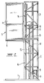
- the lift structure in accordance with the invention includes a base 1 and associated tower structure, generally designated as 2.
- the base 1 may be located on any suitable flat surface within a lift-well provided in a building structure.
- the flat surface will be in the form of a cement or concrete slab of a suitable size.
- the base and associated tower structure may in fact simply be appropriately located on the ground.
- the tower structure 2 can take a variety of forms, but in the preferred embodiment illustrated is in the form of a lattice-work of upright members, crossmembers, supporting struts etc.
- the tower structure will be of a modular construction with individual units of a length substantially the same as the height of the car or cage of the lift. It should be understood, however, that the actual length of travel of the lift may be varied dependent upon the spatial requirements of the building in which the lift is to be installed. In other words, additional unit lengths of tower may be adapted for ready positioning (installation) as desired - dependent upon the number of storeys in the building, for example.
- a suitable modular unit extension to the tower structure 2 is illustrated at 3.
- a car support means Associated with the tower structure 2 there is provided a car support means.
- the support means takes the form of a support sling 4 adapted to extend laterally from the tower structure 2, in a cantilever-type manner. It should be understood, however, that other means are possible for suspending a lift car or cage 5 in the desired position.
- a car frame 5 Located in any known manner on the car sling 4 is a car frame 5, having a number of panels 6 associated therewith and constituting the walls thereof. It should be understood, however, that it would be possible for the car frame 5 not to include any such walls, nor even a roof, but merely to involve a floor. Means in the form of a guide assembly are also provided for controlling the direction of movement of the car assembly (sling 4, frame 5 and associated panels 6).
- the direction controlling means may be in the form of one or more shaped rail(s) extending along substantially the entire vertical length (height) of the tower structure 2 and adapted to co-operate with complementary shaped protrusions - in the form perhaps of rail(s), roller(s), wheel(s) - located appropriately on the car assembly.
- a pneumatically-actuated drive system In order to impart motion to the car assembly, whereby to allow for selective vertical upward or downward movement as required, a pneumatically-actuated drive system is provided.
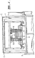
- the drive system includes a motor 8, a so-called power pack 9, a cross-head 10 having associated therewith at least one sprocket wheel 11, a pneumatic cylinder 12 and associated ram 13 (of an appropriate size), and one or more chains, cables or the like 14.
- the arrangement is such that, in use, for each unit extension (or retraction) of the pneumatic ram 13, the car assembly will travel through two similar units (in the appropriate direction, that is upwardly or downwardly). It should be understood, however, that the ratio of ram extension to car assembly travel may be readily varied.
- the cylinder 12 may be telescoping in form (or any known type).
- a clevis-mounted hydraulic cylinder 12 housed on the base 1 within the tower structure 2, supports a cross-head 10 having pulley(s), sprocket wheel(s) or the like associated therewith.
- the ropes or chains extending around and from said pulleys, sprocket wheels or the like attach on one side to the car sling 4 and to the base 1 on the other side of centre.
- the power pack 9 preferably a hydraulic power pack and fitted with solenoid valves, restrictor, non- return valves and pressure gauge
- the cylinder 12 will operate at a predetermined ram speed, for example 20 ft. per minute.
- a ram speed could be responsible for a correspondingly increased car travel speed, for example 40 ft. per minute.
- a single-phase motor may be employed as the drive motor 8.
- three-phase current may be employed, with the result that a three-phase motor may be more appropriate in certain circumstances.
- Braking means of any known type, as for example solenoid braking means, may also be provided.
- control means may include a demand button at each level of the building structure and a start- stop button in the car assembly itself.
- the tower structure 2 may be provided with so-called limit switches 16 at each level or landing thereof, with such limit switches 16 being operable to effectively de-energize the drive motor 8 upon arrival of the car or cage 5 at a respective or desired level or landing of the overall structure.
- an appropriate communication system as for example a telephone or the like, may be installed in the car or cage 5 whereby to allow for communication with persons outside the car 5, as for example in times of emergency.
- the car 5 may be equipped with lighting of any known type. Preferably, however, all lighting and controls are of low-voltage type.
- the car 5 may also be . equipped with a battery to operate as a stand-by to provide emergency lighting, as for example in the instance of power failure.
- a landing door assembly of any suitable type.
- the or each landing door is adapted to be affixed to the.tower or building in any known manner, as for example by bolting, and may be fitted with a lock of the so-called electro-mechanical type whereby to prevent unauthorized opening of that door at any time when the car or cage 5 is not itself present at the particular level or landing concerned.
- the or each landing door may also be provided with a technician's lock release assembly (not shown), whereby to allow ready access thereto, and to the interior of the tower, for purposes of service, repair and/or maintenance. Doors or the like need not be provided on the car or cage 5 itself.
- the car or cage 5 will have associated therewith means allowing for ready access thereto, such means taking the form of a door sill and frame assembly and an associated sliding door arrangement.
- each landing door will be appropriated hinged and fitted "flush" with the well lining of the overall lift structure.
- These doors need not be fire-rated, but will generally be fitted with an automatic closing means, an electrical interlocking means and preferably electrically and/or mechanically actuated locks.
- the applicant's arrangement is so designed as to allow for ready installation (location) in a "well” provided in a building structure.
- the car assembly is so dimensioned as to allow a minimum of clearance with the walls of the "well".
- Such a configuration will generally speaking obviate the need for separate doors on the car assembly, although it will of course be necessary to provide appropriate doors (of any known type) at each landing.
- the lift pit, motor and overhead space required will be kept to a minimum, an important factor in situations where available space is at a premium.
Landscapes
- Engineering & Computer Science (AREA)
- Automation & Control Theory (AREA)
- Structural Engineering (AREA)
- Conveying And Assembling Of Building Elements In Situ (AREA)
- Types And Forms Of Lifts (AREA)
Applications Claiming Priority (2)
| Application Number | Priority Date | Filing Date | Title |
|---|---|---|---|
| AU491082 | 1982-07-16 | ||
| AU4910/83 | 1982-07-16 |
Publications (2)
| Publication Number | Publication Date |
|---|---|
| EP0103951A2 true EP0103951A2 (de) | 1984-03-28 |
| EP0103951A3 EP0103951A3 (de) | 1985-02-06 |
Family
ID=3695355
Family Applications (1)
| Application Number | Title | Priority Date | Filing Date |
|---|---|---|---|
| EP83304138A Withdrawn EP0103951A3 (de) | 1982-07-16 | 1983-07-15 | Lasttransfergerät |
Country Status (2)
| Country | Link |
|---|---|
| EP (1) | EP0103951A3 (de) |
| AU (1) | AU1686583A (de) |
Cited By (4)
| Publication number | Priority date | Publication date | Assignee | Title |
|---|---|---|---|---|
| WO2003101877A1 (fr) * | 2002-05-31 | 2003-12-11 | Tarasov Aleksandr Vladimirovic | Ensemble de levage |
| CN108821063A (zh) * | 2018-07-13 | 2018-11-16 | 辽宁科技大学 | 模块化二维电梯组及其运行控制方法 |
| CN117819320A (zh) * | 2023-12-04 | 2024-04-05 | 中联重科建筑起重机械有限责任公司 | 施工升降机的运行权限的控制系统、方法以及施工升降机 |
| CN119683438A (zh) * | 2025-02-27 | 2025-03-25 | 辛格林电梯有限公司 | 一种移动式电梯 |
Families Citing this family (1)
| Publication number | Priority date | Publication date | Assignee | Title |
|---|---|---|---|---|
| CN114920097B (zh) * | 2022-06-07 | 2023-08-01 | 上海三菱电梯有限公司 | 电梯群管理方法 |
Family Cites Families (7)
| Publication number | Priority date | Publication date | Assignee | Title |
|---|---|---|---|---|
| DE12220C (de) * | C. W. BALDWIN in London | Neuerungen an hydraulischen Fahrstühlen | ||
| US2088690A (en) * | 1935-08-14 | 1937-08-03 | Inclinator Company Of America | Elevator |
| US2860729A (en) * | 1956-01-12 | 1958-11-18 | Essex Conveyors Inc | Safety lifting device |
| FR1486182A (fr) * | 1966-07-08 | 1967-06-23 | Dispositif de commande hydraulique pour cabines de monte-charge, ascenseurs et analogues | |
| GB1496878A (en) * | 1973-11-01 | 1978-01-05 | Becker Equipment & Lifts Ltd | Hydraulic lift mechanism |
| GB1438727A (en) * | 1973-12-10 | 1976-06-09 | Sims A F | Hydraulically operated building hoist |
| NZ202555A (en) * | 1981-11-24 | 1985-07-12 | N G Cooper | Lift for personnel or goods raised and lowered by cable & pulley mounted on hydraulic cylinder & piston arrangement |
-
1982
- 1982-07-16 AU AU16865/83A patent/AU1686583A/en not_active Abandoned
-
1983
- 1983-07-15 EP EP83304138A patent/EP0103951A3/de not_active Withdrawn
Cited By (5)
| Publication number | Priority date | Publication date | Assignee | Title |
|---|---|---|---|---|
| WO2003101877A1 (fr) * | 2002-05-31 | 2003-12-11 | Tarasov Aleksandr Vladimirovic | Ensemble de levage |
| CN108821063A (zh) * | 2018-07-13 | 2018-11-16 | 辽宁科技大学 | 模块化二维电梯组及其运行控制方法 |
| CN108821063B (zh) * | 2018-07-13 | 2023-06-09 | 辽宁科技大学 | 模块化二维电梯组及其运行控制方法 |
| CN117819320A (zh) * | 2023-12-04 | 2024-04-05 | 中联重科建筑起重机械有限责任公司 | 施工升降机的运行权限的控制系统、方法以及施工升降机 |
| CN119683438A (zh) * | 2025-02-27 | 2025-03-25 | 辛格林电梯有限公司 | 一种移动式电梯 |
Also Published As
| Publication number | Publication date |
|---|---|
| EP0103951A3 (de) | 1985-02-06 |
| AU1686583A (en) | 1984-01-19 |
Similar Documents
| Publication | Publication Date | Title |
|---|---|---|
| Strakosch | The vertical transportation handbook | |
| US4287967A (en) | Self-supporting and self-contained elevator | |
| AU675843B2 (en) | Traction sheave elevator with drive machine below | |
| RU2283270C2 (ru) | Система лифтов | |
| EP0094395B1 (de) | Aufhebevorrichtung | |
| US20090081010A1 (en) | Inclined Conveyance for Multi-storied Automotive Parking | |
| EP0103951A2 (de) | Lasttransfergerät | |
| CN201343337Y (zh) | 一种可节省空间的家用电梯 | |
| EP0020825A1 (de) | Apparat zum Befördern von Lasten zwischen verschiedenen Höhenlagen | |
| CN217732371U (zh) | 链轮曳引式别墅电梯 | |
| JPH11322284A (ja) | 家庭用昇降設備 | |
| EP0057701A1 (de) | Lastübertragungsvorrichtung | |
| JPS62230587A (ja) | エレベ−タ装置 | |
| WO2000030967A1 (en) | A multi-cage lift in pair | |
| CN214217848U (zh) | 一种链式家用载人升降电梯 | |
| JPS63202579A (ja) | エレベ−タの更新工法 | |
| RU2234451C1 (ru) | Вертикальный подъемник для лиц с ограниченными физическими возможностями | |
| AU2010214698A1 (en) | A residential lift | |
| CN113120726A (zh) | 一种适用于老小区改造的外装电梯 | |
| US5695024A (en) | Car operated safety gate for horizontally transferrable elevator cab | |
| CN107043073B (zh) | 通道隐蔽型的龙门提升机 | |
| WO2003013996A1 (en) | Hydraulic lift with the machine room incorporated into the hoist way | |
| JP2000007253A (ja) | 小形エレベータ装置 | |
| CN223254664U (zh) | 一种无机房货梯布置结构 | |
| Ismail | TRANSPORTATI ON SYSTEMS IN BUI LDI NGS |
Legal Events
| Date | Code | Title | Description |
|---|---|---|---|
| PUAI | Public reference made under article 153(3) epc to a published international application that has entered the european phase |
Free format text: ORIGINAL CODE: 0009012 |
|
| AK | Designated contracting states |
Designated state(s): DE FR GB IT NL SE |
|
| PUAL | Search report despatched |
Free format text: ORIGINAL CODE: 0009013 |
|
| AK | Designated contracting states |
Designated state(s): DE FR GB IT NL SE |
|
| 17P | Request for examination filed |
Effective date: 19850806 |
|
| STAA | Information on the status of an ep patent application or granted ep patent |
Free format text: STATUS: THE APPLICATION HAS BEEN WITHDRAWN |
|
| 17Q | First examination report despatched |
Effective date: 19860523 |
|
| 18W | Application withdrawn |
Withdrawal date: 19860613 |
|
| RIN1 | Information on inventor provided before grant (corrected) |
Inventor name: PERKINS, REX HENRY |