EP0104023B1 - Appareil et procédé produisant un signal synthétique de piste de commande pour machines à bande vidéo - Google Patents
Appareil et procédé produisant un signal synthétique de piste de commande pour machines à bande vidéo Download PDFInfo
- Publication number
- EP0104023B1 EP0104023B1 EP83305224A EP83305224A EP0104023B1 EP 0104023 B1 EP0104023 B1 EP 0104023B1 EP 83305224 A EP83305224 A EP 83305224A EP 83305224 A EP83305224 A EP 83305224A EP 0104023 B1 EP0104023 B1 EP 0104023B1
- Authority
- EP
- European Patent Office
- Prior art keywords
- signal
- control track
- tape
- reproducing
- head
- Prior art date
- Legal status (The legal status is an assumption and is not a legal conclusion. Google has not performed a legal analysis and makes no representation as to the accuracy of the status listed.)
- Expired - Lifetime
Links
- 238000000034 method Methods 0.000 title claims description 21
- 230000007704 transition Effects 0.000 claims description 24
- 230000003111 delayed effect Effects 0.000 claims description 13
- 230000008878 coupling Effects 0.000 claims description 7
- 238000010168 coupling process Methods 0.000 claims description 7
- 238000005859 coupling reaction Methods 0.000 claims description 7
- 230000001360 synchronised effect Effects 0.000 claims description 4
- 230000004044 response Effects 0.000 claims description 3
- 230000002463 transducing effect Effects 0.000 claims description 3
- 239000003990 capacitor Substances 0.000 description 14
- 230000033001 locomotion Effects 0.000 description 7
- 238000005070 sampling Methods 0.000 description 6
- 230000000694 effects Effects 0.000 description 5
- 238000010586 diagram Methods 0.000 description 4
- 239000000463 material Substances 0.000 description 4
- 238000004519 manufacturing process Methods 0.000 description 3
- 230000004048 modification Effects 0.000 description 3
- 238000012986 modification Methods 0.000 description 3
- 238000012937 correction Methods 0.000 description 2
- 230000035945 sensitivity Effects 0.000 description 2
- 230000002411 adverse Effects 0.000 description 1
- 230000002950 deficient Effects 0.000 description 1
- 238000011161 development Methods 0.000 description 1
- 230000018109 developmental process Effects 0.000 description 1
- 238000009432 framing Methods 0.000 description 1
- 238000003780 insertion Methods 0.000 description 1
- 230000037431 insertion Effects 0.000 description 1
- 230000007257 malfunction Effects 0.000 description 1
- 230000007246 mechanism Effects 0.000 description 1
- 230000008520 organization Effects 0.000 description 1
- 230000000737 periodic effect Effects 0.000 description 1
- 238000004904 shortening Methods 0.000 description 1
Images

Classifications
-
- G—PHYSICS
- G11—INFORMATION STORAGE
- G11B—INFORMATION STORAGE BASED ON RELATIVE MOVEMENT BETWEEN RECORD CARRIER AND TRANSDUCER
- G11B19/00—Driving, starting, stopping record carriers not specifically of filamentary or web form, or of supports therefor; Control thereof; Control of operating function ; Driving both disc and head
- G11B19/20—Driving; Starting; Stopping; Control thereof
-
- G—PHYSICS
- G11—INFORMATION STORAGE
- G11B—INFORMATION STORAGE BASED ON RELATIVE MOVEMENT BETWEEN RECORD CARRIER AND TRANSDUCER
- G11B15/00—Driving, starting or stopping record carriers of filamentary or web form; Driving both such record carriers and heads; Guiding such record carriers or containers therefor; Control thereof; Control of operating function
- G11B15/18—Driving; Starting; Stopping; Arrangements for control or regulation thereof
- G11B15/26—Driving record carriers by members acting directly or indirectly thereon
- G11B15/28—Driving record carriers by members acting directly or indirectly thereon through rollers driving by frictional contact with the record carrier, e.g. capstan; Multiple arrangements of capstans or drums coupled to means for controlling the speed of the drive; Multiple capstan systems alternately engageable with record carrier to provide reversal
-
- G—PHYSICS
- G11—INFORMATION STORAGE
- G11B—INFORMATION STORAGE BASED ON RELATIVE MOVEMENT BETWEEN RECORD CARRIER AND TRANSDUCER
- G11B15/00—Driving, starting or stopping record carriers of filamentary or web form; Driving both such record carriers and heads; Guiding such record carriers or containers therefor; Control thereof; Control of operating function
- G11B15/18—Driving; Starting; Stopping; Arrangements for control or regulation thereof
- G11B15/46—Controlling, regulating, or indicating speed
- G11B15/467—Controlling, regulating, or indicating speed in arrangements for recording or reproducing wherein both record carriers and heads are driven
- G11B15/4673—Controlling, regulating, or indicating speed in arrangements for recording or reproducing wherein both record carriers and heads are driven by controlling the speed of the tape while the head is rotating
- G11B15/4675—Controlling, regulating, or indicating speed in arrangements for recording or reproducing wherein both record carriers and heads are driven by controlling the speed of the tape while the head is rotating with provision for information tracking
Definitions
- This invention relates to a method and apparatus for controlling tape speed in a video tape recording and/or reproducing machine and more particularly to a method and apparatus for generating a synthetic control track signal during playback from reproduced video vertical synchronizing information for use in servo controlling the tape drive.
- Magnetic video tape recording and/or reproducing machines generally operate by passing magnetic recording tape in transducing relation to one or more rotating transducers or heads which scan the tape at a very high rate relative to the tape speed.
- the heads record a plurality of generally parallel tracks on the tape which contain video information, and the same heads or other heads reproduce the recorded video information signal during playback by scanning the recorded tracks.
- a control track head records control track signal information typically on a longitudinal track along one side of the tape simultaneously as video information is recorded by a rotating video head scanning along the tape and spaced from the longitudinally extending control track.
- the control track signal information typically is a frame rate square wave.
- the frame rate control track signal changes state once for each field of recorded video information.
- the control track signal information also often includes periodic color framing pulses for identifying specific fields in a multifield sequence.
- the longitudinal transport speed of the tape must be accurately controlled during playback and, for that reason, the tape is moved by a motor driven capstan controlled by a capstan servo mechanism in accordance with a capstan tachometer signal and with the timing relationship between a reference vertical sync signal and control track signal information reproduced from the tape during playback.
- control track information may not be recorded during an insert edit, and it may not be recorded due to various malfunctions and the like. In other cases, the control track information may be inverted in phase.
- the reproducing head is mounted at the end of a movable element that is controllable to move the head transversely relative to the longitudinal direction of a recorded track so as to maintain the head on the track to provide a reproduced signal of superior quality, even when the tape is being transported at a speed other than normal reproducing speed, such as during special motion effects of still frame reproducing, slow motion reproducing and fast motion reproducing.
- Such systems generate an error signal indicating whether the head is off track and the error signal is used in a head positioning servo for moving the movable element to return the head to the center of the recorded track.
- the error signal will provide an indication of the tape speed deviation from normal tape speed as well as head to tape position deviation and this error.
- This error can be used to control the capstan servo to generally maintain proper tape speed and proper head to tape position.
- the automatic scan tracking error signal is not entirely reliable in providing control of the capstan servo because it does not rely on any well defined timing signals and is subject to mechanical and electrical variations which can affect the accuracy of the control of the capstan servo.
- an object of this invention is to provide a new and improved method and apparatus for generating a synthetic control track signal for use by the capstan servo for controlling tape speed in a video tape recording and/or reproducing machine whereby the adverse effects of improperly recorded or missing control track signals are obviated. or reduced.
- An additional or alternative object is to provide a new and improved synthetic control track signal which is generated during playback using vertical synchronizing signal information.
- An additional or alternative object is to provide a new and improved method and apparatus for generating a synthetic control track signal during video playback operations for use in synchronizing the transport of the tape to system reference while simultaneously recording a new control track signal on the tape.
- the invention provides a servo for controlling, with respect to a reference timing signal, the relative transport speed between an information transducing head and a recording medium in a recording and/or reproducing machine having a control head for reproducing a control timing signal recorded along the medium, so that the time base of the control timing signal is indicative of the said relative transport speed, and an information head for reproducing recorded information signals, said information signal containing a known timing component related in time to the control timing signal and whose time base corresponds to the said relative transport speed, the servo being characterised by a comparator for comparing the reference timing signal and the control timing signal to generate an error signal in accordance with timing differences between the compared signals; means for generating a synthesized control timing signal in response to the occurrence of the timing component contained in the reproduced information signal; means for coupling the synthesized control timing signal to the comparator in place of the reproduced control timing signal; and means responsive to the error signal generated by the comparator upon the comparison of the reference timing signal and the synthesized control timing signal for controlling
- the invention provides a magnetic video tape recording and/or reproducing machine of the type which has a rotary reproducing head, a capstan, a capstan servo for controlling the capstan during recording and/or reproducing operations with a tape whose transport is controlled by the capstan, and a stationary control track head for recording and/or reproducing control track signal information for use by the capstan servo, characterised by a circuit for generating a synthetic control track signal which has not been recorded on the tape, this circuit comprising means for generating a square wave signal having a predetermined period, means for coupling said square wave signal generating means to be synchronized to a vertical sync signal of the video information signal reproduced by said rotary reproducing head, and means for inserting a narrow pulse in said square wave signal adjacent a predetermined transition and at a predetermined multiple of the square wave period.
- the invention also provides a method of recording a control track signal longitudinally along a tape transported in a helical path under the control of a capstan servo as video information is reproduced from the tape, the reproduced video information containing a vertical synchronisation signal and being reproduced by a helical scan video tape recording and/or reproducing machine including a control track signal record and/or reproduce system and a video information signal record and/or reproduce system, the method being characterised by generating a synthesized control track signal from the vertical synchronisation signal contained in the reproduced video information; controlling the capstan servo with the synthesized control track signal; disabling the control track signal record and/or reproduce system from reproducing recorded control track signals while enabling such system to record control track signals; and enabling the video information signal record and/or reproduce system to reproduce recorded video information signals while disabling such system from recording video information signals.
- the invention also provides a method of generating a synthetic control track signal for a magnetic video tape recording and/or reproducing machine of the type which has a capstan, a capstan servo for controlling the capstan during recording and/or reproducing operations with a tape whose transport is controlled by the capstan and a stationary control track head for recording and/or reproducing control track signal information for use by the capstan servo, the method comprising: generating a square wave signal of a predetermined period synchronously relative to the occurrence of a vertical synchronisation signal of video information reproduced from the tape by a video head; and inserting a narrow pulse in said square wave signal adjacent a predetermined square wave signal transition and at a predetermined multiple of the square wave period.
- Figure 1A is a block diagram of a circuit for generating a synthetic control track signal in accordance with this invention
- FIG. 1B is a block diagram of a common capstan servo arranged to be operated in accordance with this invention.
- FIGS. 2(a) through 2(f) are timing diagrams illustrating the relationship between normal and synthetic control track signal information, vertical synchronizing information, and the capstan servo ramp voltage;
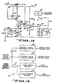
- FIG. 3 illustrates a detailed schematic of the control track error detector circuit shown in FIG. 1B.
- FIG. 4 is a block diagram of a video signal record and playback system and a control track signal record and playback system arranged so that normal control track record operations can occur selectively during video playback operations.
- the present invention is directed to a method and apparatus for generating a synthetic control track signal during the reproduction of recorded video information for use in a video tape recording and reproducing machine.
- the synthetic control track signal is utilized to control the capstan servo for moving the tape at the normal reproducing speed when the control track signal recorded on tape is defective or nonexistent so that the tape transport is maintained in synchronism with the system reference. It should be appreciated that when many helical wrap recording machines perform an insert edit operation, i.e., they record new material over a prior recording, the new material is added in an insert edit mode whereby a new control track signal is not recorded.
- the present invention generates a synthetic control track signal utilizing recorded video information signals, which is applied to the capstan servo otherwise operated in a conventional manner.
- the synthetic control track generating circuitry embodying the present invention is also adapted to insert the color frame field identification pulses in the synthetically generated control track signal as is desired. In other words, a "field one" identification pulse is applied to the control track square wave signal as is desired.
- Another feature of the present invention is that the synthetic control track signal can be used to control the capstan servo to drive the tape at the proper speed during reproducing, and if a control track signal missing from the recorded control track, the apparatus can simultaneously activate the control track record circuitry for the purpose of recording a control track signal at the missing location. Once the control track is recorded in the conventional manner, then the tape may be played in the normal fashion by any conventional recording and reproducing machine.
- the synthetic control track signal generating circuitry utilizes the field one identification signal from a common color framer circuit included in video tape recording and/or reproducing machines, which in and of itself does not form a part of the present invention.
- the field one identification signal, together with playback vertical sync are used to generate the synthetic control track signal. It should be appreciated that the relationship of the conventionally recorded control track signal to vertical sync is such that each field rate transition of the control track signal is recorded on the tape approximately half way between the occurrences of successively reproduced vertical sync signals.
- the transitions of the synthetic control track are essentially coincident with vertical sync, which means that they are offset relative to the occurrences of the conventionally recorded control track transitions, but the offset can be compensated for in the conventional capstan servo, with only slight modification.
- control track signals are recorded and reproduced by a fixed head and that the control track transitions are reproduced in response to the tape being moved relative to the control track head.
- speed of the tape is relatively slow compared to the speed of rotation of the head that scans the recorded video tracks during reproducing. Since the synthetic control track signal is essentially derived from active video information being read by the rotated video head mounted on the scanning drum, the movement of the rotated head in the longitudinal direction of the tape as it reproduces video information is approximately 100 times the speed of movement of the tape past the control track head. For this reason, it is necessary to compensate for this significant difference in relative head to tape speeds.
- the control track error detector includes means for generating a voltage ramp by charging a capacitor and at a particular time, the value of the ramp is sampled to obtain a control track determined tape speed related error voltage that is applied to the capstan servo for the purpose of controlling the capstan drive and, hence, tape speed.
- the ramp is reset by a reference frame sync related signal and the ramp is sampled by the occurrence of a reproduced control track transition.
- the relative timing of the sampling of the ramp in accordance with the present invention is slightly different from the timing of the sampling in the conventional capstan servo, but it is approximately the same by virtue of the fact that the synthetic control track signal is essentially synchronized to the reproduced off tape vertical sync extractred from the reproduced video signal.
- the reference vertical sync that is applied to reset the ramp is slightly advanced in time relative to the time of occurrence of the actual reference vertical sync used for such purpose when the servo is being operated under the control of the synthetic control track signal.
- the synthetic control track signal has transitions coincident with vertical sync which means that the occurrence of a control track transition is approximately 180° out of phase relative to a conventional control track transition.
- the ramp generator has a ramp slope that is 100 times steeper than the slope of the ramp signal used in a conventional capstan servo, which means that in the capstan servo of the present invention the ramp signal generated in the control track error detector must be sampled much sooner relative to a ramp signal in the conventional capstan servo.
- the reference vertical sync signal which resets the ramp when a synthetic control track is used is normally delayed in the conventional capstan servo by a full field in a circuit that does not in itself form a part of the present invention.
- the delayed reference vertical sync will be advanced in time a small amount relative to that found in the conventional capstan servo. This has the effect of providing the final correction to the capstan servo so that the control track related error signal that the capstan servo uses to control the capstan speed is essentially identical, whether the synthetic control track or the conventional control track signal is used to sample the ramp signal.
- FIG. 1A Vertical sync is extracted from the reproduced video information by conventional circuitry (not shown) found in the aforementioned Ampex manufactured video tape recording and/or reproducing machine as the playback video head scans the various tracks, and is provided at an input 12 and coupled to the clock input of a flip-flop 16.
- a No. 1 field identification signal (of a four field sequence in a NTSC format color video information signal and of an eight field sequence in a PAL format color video information signal) also conventionally extracted from the reproduced video information signal is provided to a delay one shot circuit 28.
- the delay circuit 28 provides an output signal to the "set" input terminal of the flip-flop 16 to synchronize the same to the occurrence of the field No. 1 identification signal.
- the time constant of the one shot circuit 28 is set to properly locate the leading edge of the field No. 1 identification signal relative to the proximate control track transition of the synthetic control track signal into which the identification signal is inserted.
- the flip-flop 16 is clocked by play back vertical sync and operates as a divide by two divider and provides a 30 Hertz (Hz) frame rate square wave signal at its output.
- the period of the square wave signal generated by the flip-flop 16 is therefore equal to that of a normal control track signal.
- the 60 Hz rate transitions of the square wave signal are coincident with the 60 Hz vertical sync signal, whereas the transitions of conventional control track signals are offset relative to vertical sync as is apparent from FIGS. 2(a) and 2(c).
- the square wave signal is employed to form a synthetic control track signal and, preferably, is combined with a short pulse to provide field identification information as is desired.
- the field identification pulse is added to the synthetic control track square wave signal synthesized by the flip-flop 16.
- the circuitry shown in FIG. 1 provides a narrow pulse after the field No. 1 identification signal is received. It is delayed by the amount of the delay provided by the one shot 28.
- the delay circuit 28 times out and its Q output is coupled to trigger a monostable multivibrator, or one-shot 30.
- the one-shot 30 responsively produces a narrow pulse at the proper time for adding to the square wave signal as the desired field identification signal and has a controlling time constant that is set to effect the generation of a field No.
- the field No. 1 identification signal is inserted in the synthesized square wave signal to occur every two periods of the signal, since the identification signal is at a rate of 15 HZ (or 1/2 the frequency of the 30 HZ square wave signal).
- the field No. 1 identification signal is at a rate of 1/8 the frequency of the synthesized square wave signal, hence, is inserted to occur every four periods of the synthesized signal.
- the output of the one-shot 30 is combined with the square wave of the flip-flop 16 in an NAND gate 18, and a synthetic control track signal having field identification signal information is produced at an output 32.
- the timing of the synthetic control track is different from that of the conventional control track signal, which signal requires some modification for use in the operation of a capstan servo.
- the control track signal transitions occur between vertical sync pulses as shown in FIGS 2(a) and 2(c).
- the capstan servo 41 included in the aforementioned Ampex manufactured video production recorder includes a control track error detector 43 that generates a control track related error signal in the form of a tape speed related voltage level that controls a following voltage controlled oscillator 45, which provides an output signal at a frequency that determines the speed of the capstan motor.
- This output signal is coupled to one input of a capstan tachometer error detector 47 and serves as a reference signal for comparison to the capstan tachometer signal.
- This error detector 47 provides a capstan servo error signal that is coupled to the capstan motor drive amplifier circuit 49 that responsively controls the drive provided to the capstan motor (not shown) to maintain the transport of the tape at the desired speed.
- the control track related error signal is generated by sampling a ramp output of a linear ramp generator, with the sample being taken and held at a particular time, such as at the time of a control track transition.
- the ramp is reset by a delayed reference vertical sync signal.
- the servo is controlled by a conventional control track signal as shown. Samples are taken at the occurrences of control track transitions, which nominally occur at the midpoints of the occurrences of the voltage ramp signals when the tape is transported at the correct normal playback speed.
- Variations in the occurrences of the control track transitions relative to the generation of the ramp signal result in the ramp signal being sampled at points along the slope of the ramp signal which are either higher (tape speed too slow) or lower (faster tape speed too fast) than the midpoint of the ramp signal.
- the slope of the ramp must be increased because the head rotates, hence, scans along the tape much faster than the longitudinal speed of the tape past the control track playback head.
- the video head passes a longitudinal length of tape which corresponds to the distance the tape moves relative to the conventional stationary control track playback head during the reproduction of one video field.
- the slope of the ramp is sharply increased as shown by comparing FIGS. 2(b) with an exaggerated slope shown in FIG 2(e).
- the slope is increased by switching switch 42 (FIG. 3) to a position opposite that shown, which effectively removes the larger capacitor 44 from the ramp generating circuit included in the control track error detector 43 and indicated generally at 51.
- the ramp is reset by switch 52 responsive to the aforementioned delayed reference vertical sync.
- the delayed reference vertical sync is generated with an amount of delay which is changed depending upon whether regular or synthetic control track signals are used in the control track error detector 43.
- the delayed vertical sync is normally delayed by an interval corresponding approximately to the time of a full video field and in the synthetic control track mode, it is delayed by a slightly lesser amount to form an advanced reference vertical signal, as shown by comparing FIGS. 2(a) with 2(d).
- the ramp is therefore reset slightly earlier by the advanced reference vertical signal than would otherwise occur, as seen by comparing FIGS. 2(b) and 2(c).
- FIG. 3 Either the normal control track or the synthetic control track signal is selected for coupling to an input terminal 38 by an operator controlled switch 53 shown in FIG. 1B. Similarly, the normally delayed or advanced reference vertical signal is selected for coupling to an input 40 by another operator controlled switch 55 shown in FIG. 1B, the switches 53 and 55 being conjointly operated.
- the switch 42 is in the position shown, and capacitors 44 and 46 are connected to an input of a buffer 48. The capacitance of the capacitor 44 is about 100 times greater than the capacitance of the capacitor 46, and both capacitors are charged by a current source 50, producing a ramp voltage at the output of the buffer 48.
- the delayed reference vertical sync signal which is in the form of a pulse train, received at input 40 resets the ramp by moving a switch 52 to the illustrated position whereby the charges on the capacitors 44 and 46 are drained to ground.
- the switch 52 is activated by the delayed reference vertical sync applied on input 40 through the switch 55 (FIG. 1B).
- an active signal is placed on line 92 by the simultaneous closure of switch 55a. This causes switches 42 and a switch 94 to be switched to respective positions opposite those that are shown.
- the ramp voltage output of the buffer 48 is sampled by the control track sample pulses corresponding to control track transitions, which occur at the 60 Hz field rate, and actuate a switch 54.
- the switch 54 is closed for a very short time responsive to a control track sample signal being applied thereto via line 38 and simultaneously the supply of current by source 50 is interrupted to maintain a constant level of charge on the capacitors 44 and 46 during the sampling interval.
- the sampled voltage is stored in a capacitor 56, which provides an input to a unity gain buffer 58.
- the output of the buffer 58 provides a control signal via amplifier 60 and line 82 to the voltage controlled oscillator 45 included in the capstan servo 41.
- the switch 42 is in the position shown, and the capacitor 44 is in the circuit and can be charged. If the synthetic control track is to be used, the switch 42 is switched as described herein before to the position alternate to that shown to isolate the capacitor 44 from the circuit. Since the capacitance of the capacitor 44 is about 100 times greater than that of the capacitor 46, the slope of the ramp will be about 100 times greater without the capacitor 44 as described hereinbelow.
- the output of the buffer 58 is applied to an amplifier 60 which includes a feedback network having four diodes 62, 64, 66 and 68, connected as shown.
- the diodes 62, 64, 66 and 68 limit the dynamic range of the correction by limiting the maximum speed error signal which may be generated as a result of a possible track jump that can occur with a machine that has an automatic scan tracking system of the type previously described.
- Existing video tape recording and/or reproducing machines are arranged to have their control track signal record and playback system and video signal record and playback system in the same record or playback mode other than such machines arranged to perform confidence recording operations
- the video signal record system and video signal playback system are simultaneously enabled so that as video information is being recorded by one video head a separate video head reproduces previously recorded video information.
- the transport of the tape is not servo controlled with respect to recorded control track.
- the generation of the synthetic control track signs in accordance with the present invention now makes it possible to synchronously operate a video tape recording and/or reproducing machine so that normal video playback operations and control track record operations can synchronously occur relative to the system reference in the absence of a control track signal or the presence of an improperly recorded control track signal.
- this is made possible because the synthetic control track signal permits the control of the transport of the tape synchronously with the system reference during normal video playback operations without need of control track signals reproduced from the tape.
- the synthetic control track signal is generated from the vertical sync signal extracted from the reproduced video information signal.
- the capstan record/playback signal system and video record/ playback signal system can be in opposite operating modes, including the control track signal system in a record mode while the video signal system is in a playback mode. This enables the control track signal system to be operated to record a new control track signal on a tape when the video signal system is reproducing previously recorded video information from the same tape.
- FIG. 4 illustrates a control track signal and video signal record and playback system 91 organization of a typical video tape recording and/or reproducing machine, such as the aforementioned Ampex manufactured video production recorder.
- the control track signal playback system 93 has its control track signal input coupled to a control track playback head (not shown) and the control track signal record system 95 has its control track signal output coupled to a control track record head (not shown).
- a single head serves to record and playback control track signals with respect to the tape, that head being switched electronically to the proper part of the control track signal system in accordance with operating mode selected for the system.
- the video signal record system 97 has its video signal output coupled to a video record head (not shown) and the video signal playback system 99 has its video signal input coupled to a video playback head (not shown).
- a single video head can be used for both recording and playback operations, with an electronically controlled switch coupling the video head to the proper part of the video signal system in accordance with the operating mode seleted for the system.
- the aforedescribed control track and video signal systems may be conventional systems found in existing video tape recording and/or playback machines.
- the operating modes of the control track signal system and video signal system are controlled relative to the operation of the synthetic control track signal generator so that the two systems can be in opposite operating modes, namely, the control track signal system in the record mode while the video signal system is in the playback mode.
- This is achieved by the generation of two operator initiated commands; one being the control track record command that is coupled to enable the control track record system 95, and the other an inverted form of the insert control track command.
- the two commands are coupled to separate inputs of an AND gate 101, for selectively disabling the video signal record system 97 while enabling the video signal playback system 99 when an insert control track command is generated coincidentally with the control track record command.
- the AND gate 101 generates logical low level output which is coupled to the video signal record system 97 and the video playback system 99 in the absence of an insert control track command, signified by a logical low level signal at the input to the AND gate.
- This logical low level signal at the output of the AND gate 101 has no effect on the control of the operative mode of the video signal system.
- a logical high level signal is coupled to the input of the AND gate 101 and, if a control track record command is also received at the input of the AND gate, the output of the AND gate is at a logical high level.
- the logical high level signal disables the video signal record system 97 while enabling the video signal playback system 99, whereby the video signal system can not be placed in a record mode but is able to be operated in the playback mode.
- the control track record command is also coupled to the control track signal record system 95 and through an inverter 103 to the control track signal playback system 93. The presence of a control track record command enables the control track record system 95 while simultaneously disabling the control track record system 93. In this manner new control track signals can be recorded on a tape through the normal operation of the control track signal record system 95 while video information is simultaneously reproduced from the tape through the normal operation of the video signal playback system 99.
- control track signals can be recorded so that the tape (or other record media) will have a properly recorded control track signal for future reproduction.
- any control track signal or other comparable timing signal recorded on tape or other record media can be synthesized in accordance with the present invention from a known timing component included in an information signal if the recorded information signal and timing signal are related in time, and the time bases of the recorded information signal and timing signal are proportional to the relative timing signal head to media speed.
Landscapes
- Television Signal Processing For Recording (AREA)
- Adjustment Of The Magnetic Head Position Track Following On Tapes (AREA)
- Extrusion Moulding Of Plastics Or The Like (AREA)
- Looms (AREA)
- Management Or Editing Of Information On Record Carriers (AREA)
Claims (14)
- Asservissement pour commander, par rapport à un signal de rythme de référence, la vitesse de transport relative entre une tête transductrice d'informations et un support d'enregistrement dans une machine d'enregistrement et/ou de reproduction ayant une tête de commande pour reproduire un signal de rythme de commande enregistré le long du support, de telle manière que la base de temps du signal de rythme de commande est représentative de ladite vitesse de transport relative, et une tête d'information pour reproduire des signaux d'information enregistrés, ledit signal d'information contenant une composante de rythme connue en relation temporelle avec le signal de rythme de commande et dont la base de temps correspond à ladite vitesse de transport relative, l'asservissement étant caractérisé par:
un comparateur (43) pour comparer le signal de rythme de référence au signal de rythme de commande en vue de générer un signal d'erreur (82) conformément à des différences de rythme entre les signaux comparés; des moyens (28,16) pour générer un signal de rythme de commande synthétisé en réponse à l'apparition de la composante de rythme contenue dans le signal d'information reproduit; des moyens (53) pour relier le signal de rythme de commande synthétisé au comparateur (43) à la place du signal de rythme de commande reproduit; et des moyens (45, 47, 49) réagissant au signal d'erreur généré par le comparateur (43) lors de la comparaison entre le signal de rythme de référence et le signal de rythme de commande synthésisé en vue de commander ladite vitesse de transport relative conformément aux différences de rythme représentées dans ledit signal d'erreur. - Asservissement selon la revendication 1, dans lequel le signal de rythme de commande reproduit est obtenu à partir d'une piste de pilotage enregistrée longitudinalement le long d'une bande et le signal de rythme de commande synthétisé est issu d'un signal de synchronisation verticale enregistré le long de la bande suivant un trajet s'étendant obliquement par rapport au sens longitudinal de la bande.
- Machine d'enregistrement et/ou de reproduction sur bande vidéo magnétique du type comportant une tête de reproduction rotative, un cabestan, un asservissement de cabestan pour commander le cabestan pendant les opérations d'enregistrement et/ou de reproduction avec une bande dont le transport est commandé par le cabestan, et une tête de piste de pilotage fixe pour enregistrer et/ou reproduire des informations de signaux de piste de pilotage destinées à être utilisées par l'asservissement de cabestan, caractérisée par un circuit (16, 28, 30, 32) pour générer un signal synthétique de piste de pilotage qui n'a pas été enregistré sur la bande, ce circuit comprenant des moyens (16) pour générer un signal à onde carrée ayant une période prédéterminée, des moyens (12) pour relier lesdits moyens générateurs de signaux à onde carrée à synchroniser avec un signal de synchronisation verticale dudit signal d'information vidéo reproduit par ladite tête de reproduction rotative, et des moyens (18, 30) pour insérer une impulsion étroite dans ledit signal à onde carrée au voisinage d'une transition prédéterminée et suivant un multiple prédéterminé de la période de l'onde carrée.
- Machine selon la revendication 3, dans laquelle lesdits moyens d'insertion d'impulsion (18, 30) comprennent un multivibrateur monostable (30) qui produit une impulsion étroite en réponse à la réception d'un signal d'identification de trame retardé qui lui est appliqué, et une porte logique (18) reliée audit multivibrateur et auxdits moyens générateurs d'ondes carrées pour combiner lesdits signaux.
- Machine selon la revendication 3 ou la revendication 4, dans laquelle lesdits moyens générateurs de signaux à onde carrée comprennent un premier dispositif numérique (16) qui génère un signal à onde carrée de fréquence image piloté par le signal de synchronisation verticale reproduit par ladite tête de reproduction rotative, et un multivibrateur monostable (28) réagissant à l'information d'identification de trame contenue dans un signal de référence multi-trames, ledit multivibrateur monostable étant relié de façon à fournir une entrée audit premier dispositif numérique (16) pour synchroniser lesdits moyens générateurs de signaux à onde carrée avec une trame prédéterminée d'une séquence multi-trames du signal de référence.
- Machine selon l'une quelconque des revendications 3 à 5, dans laquelle ledit asservissement de cabestan comprend un générateur de signaux en rampe (50,46) qui est ré-initialisé par un signal de synchronisation verticale de référence, ledit signal en rampe étant échantillonné par un circuit échantillonneur-bloqueur (54, 56) commandé par des transitions de piste de pilotage pour générer un signal d'erreur servant à commander l'asservissement de cabestan, des moyens (42, 44) étant prévus pour augmenter la pente du signal en rampe produit par le générateur de signaux en rampe d'un facteur correspondant à la différence de vitesse relative tête-bande entre la tête vidéo reproduisant l'information vidéo contenant ledit signal de synchronisation verticale et la tête de piste de pilotage; et des moyens (52) étant prévus pour ajuster le rythme de la ré-initialisation dudit générateur de signaux en rampe afin de permettre ainsi au signal en rampe produit d'être échantillonné lorsque sa pente augmente suivant la même tension nominale que celle qui se produirait si l'on utilisait le signal de piste de pilotage reproduit à partir de la bande pour générer un signal d'erreur destiné à être utilisé par l'asservissement du cabestan.
- Procédé d'enregistrement d'un signal de piste de pilotage longitudinalement le long d'une bande transportée suivant un trajet hélicoïdal sous la commande d'un asservissement de cabestan pendant que des informations vidéo sont reproduites à partir de la bande, les informations vidéo reproduites contenant un signal de synchronisation verticale et étant reproduites par une machine d'enregistrement et/ou de reproduction sur bande vidéo à enroulement hélicoïdal comportant un système d'enregistrement et/ou de reproduction de signaux de piste de pilotage et un système d'enregistrement et/ou de reproduction de signaux d'information vidéo, le procédé étant caractérisé en ce qu'il consiste à générer un signal de piste de pilotage synthétisé à partir du signal de synchronisation verticale contenu dans les informations vidéo reproduites; à commander l'asservissement de cabestan avec le signal de piste de pilotage synthétisé; à interdire au système d'enregistrement et/ou de reproduction de signaux de piste de pilotage de reproduire des signaux de piste de pilotage enregistrés tout en autorisant un tel système à enregistrer des signaux de piste de pilotage; et à autoriser le système d'enregistrement et/ou de reproduction de signaux d'information vidéo à reproduire des signaux d'information vidéo enregistrés tout en interdisant à ce système d'enregistrer des signaux d'information vidéo.
- Procédé de production d'un signal synthétique de piste de pilotage pour une machine d'enregistrement et/ou de reproduction sur bande vidéo magnétique du type comportant un cabestan, un asservissement de cabestan pour commander le cabestan pendant les opérations d'enregistrement et/ou de reproduction avec une bande dont le transport est commandé par le cabestan et une tête de piste de pilotage fixe pour enregistrer et/ou reproduire les informations de signaux de piste de pilotage destinées à être utilisées par l'asservissement de cabestan, le procédé consistant à: générer un signal à onde carrée d'une période prédéterminée de façon synchrone par rapport à l'apparition d'un signal de synchronisation verticale d'informations vidéo reproduites à partir de la bande par une tête vidéo; et à insérer une impulsion étroite dans ledit signal à onde carrée au voisinage d'une transition de signal à onde carrée prédéterminée et suivant un multiple prédéterminé de la période de l'onde carrée.
- Procédé selon la revendication 8, dans lequel ladite période prédéterminée est équivalente à la période du signal de piste de pilotage.
- Procédé selon la revendication 8 ou la revendication 9, dans lequel ladite transition prédéterminée est une transition dans le sens négatif du signal à onde carrée.
- Procédé selon l'une quelconque des revendications 8 à 10, dans lequel ledit multiple prédéterminé de la période de l'onde carrée est deux, le signal d'information vidéo ayant un format NTSC.
- Procédé selon l'une quelconque des revendications 8 à 10, dans lequel ledit multiple prédéterminé de la période de l'onde carrée est quatre, le signal d'information vidéo ayant un format PAL.
- Procédé selon l'une quelconque des revendications 9 à 12, ledit asservissement de cabestan étant du type qui comporte un générateur de signaux en rampe qui est ré-initialisé par un signal de synchronisation verticale de référence, ledit signal en rampe étant échantillonné par un circuit échantillonneur-bloqueur commandé par des transitions de piste de pilotage pour générer un signal d'erreur servant à commander l'asservissement de cabestan, ledit procédé consistant en outre, pendant une opération de reproduction de signal, à augmenter la pente du signal en rampe produit par le générateur de signaux en rampe d'un facteur correspondant à la différence de vitesse relative tête-bande entre la tête vidéo reproduisant l'information vidéo contenant ledit signal de synchronisation verticale et la tête de piste de pilotage; et à ajuster le rythme de la ré-initialisation dudit générateur de signaux en rampe afin de permettre au signal en rampe produit d'être échantillonné, afin de fournir un signal d'erreur pour l'asservissement du cabestan, suivant la même tension nominale que celle qui se produirait si l'on utilisait le signal de piste de pilotage.
- Procédé selon la revendication 13, dans lequel ladite pente est augmentée d'un facteur de 100.
Priority Applications (1)
| Application Number | Priority Date | Filing Date | Title |
|---|---|---|---|
| AT83305224T ATE63180T1 (de) | 1982-09-16 | 1983-09-07 | Geraet und verfahren fuer videobandmaschinen welches ein synthetisches steuerungsspursignal erzeugt. |
Applications Claiming Priority (2)
| Application Number | Priority Date | Filing Date | Title |
|---|---|---|---|
| US41886582A | 1982-09-16 | 1982-09-16 | |
| US418865 | 1982-09-16 |
Publications (3)
| Publication Number | Publication Date |
|---|---|
| EP0104023A2 EP0104023A2 (fr) | 1984-03-28 |
| EP0104023A3 EP0104023A3 (en) | 1986-01-02 |
| EP0104023B1 true EP0104023B1 (fr) | 1991-05-02 |
Family
ID=23659866
Family Applications (1)
| Application Number | Title | Priority Date | Filing Date |
|---|---|---|---|
| EP83305224A Expired - Lifetime EP0104023B1 (fr) | 1982-09-16 | 1983-09-07 | Appareil et procédé produisant un signal synthétique de piste de commande pour machines à bande vidéo |
Country Status (4)
| Country | Link |
|---|---|
| EP (1) | EP0104023B1 (fr) |
| JP (1) | JPS5987645A (fr) |
| AT (1) | ATE63180T1 (fr) |
| DE (1) | DE3382267D1 (fr) |
Families Citing this family (2)
| Publication number | Priority date | Publication date | Assignee | Title |
|---|---|---|---|---|
| KR930000023B1 (ko) * | 1990-06-04 | 1993-01-06 | 삼성전자 주식회사 | 테이프 콘트롤 무신호시의 서어보 제어 방법 |
| JP3194289B2 (ja) * | 1992-03-23 | 2001-07-30 | ソニー株式会社 | 記録再生装置 |
Family Cites Families (5)
| Publication number | Priority date | Publication date | Assignee | Title |
|---|---|---|---|---|
| US3968518A (en) * | 1972-08-04 | 1976-07-06 | Sony Corporation | Magnetic recording and/or reproducing apparatus for videotape editing |
| JPS50153606A (fr) * | 1974-05-30 | 1975-12-10 | ||
| US4163262A (en) * | 1976-01-02 | 1979-07-31 | Americal Telephone and Telegraph | Helical video tape recorder arrangement suitable for high quality editing |
| JPS5669981A (en) * | 1979-11-12 | 1981-06-11 | Sony Corp | Phase servo circuit |
| JPS56115084A (en) * | 1980-02-16 | 1981-09-10 | Sony Corp | Video signal reproducer |
-
1983
- 1983-09-07 EP EP83305224A patent/EP0104023B1/fr not_active Expired - Lifetime
- 1983-09-07 AT AT83305224T patent/ATE63180T1/de not_active IP Right Cessation
- 1983-09-07 DE DE8383305224T patent/DE3382267D1/de not_active Expired - Lifetime
- 1983-09-14 JP JP58170557A patent/JPS5987645A/ja active Pending
Also Published As
| Publication number | Publication date |
|---|---|
| DE3382267D1 (de) | 1991-06-06 |
| EP0104023A2 (fr) | 1984-03-28 |
| JPS5987645A (ja) | 1984-05-21 |
| ATE63180T1 (de) | 1991-05-15 |
| EP0104023A3 (en) | 1986-01-02 |
Similar Documents
| Publication | Publication Date | Title |
|---|---|---|
| US4394694A (en) | Tape synchronizing apparatus | |
| US4134130A (en) | Method and apparatus of inserting an address signal in a video signal | |
| USRE29787E (en) | Color phase matching system for magnetic video tape recordings | |
| EP0091188A1 (fr) | Servo-système multiple commandé par un microprocesseur pour appareil d'enregistrement et/ou de reproduction | |
| JPH02107079A (ja) | 磁気記録再生装置 | |
| US4672474A (en) | Synthetic control track signal producing apparatus for video tape machines | |
| US4549224A (en) | Digital video tape recorder that can be used with different television systems | |
| GB1294264A (en) | Automatic phasing of servo systems used in tape transport systems | |
| US3542949A (en) | Electronic editing device for a magnetic recording and reproducing apparatus | |
| US4679098A (en) | Video tape transport servo for variable tape speed control | |
| US5432655A (en) | Multiple channel magnetic recording and reproducing apparatus | |
| EP0104023A2 (fr) | Appareil et procédé produisant un signal synthétique de piste de commande pour machines à bande vidéo | |
| US4751586A (en) | Rotary head tape transport servo system having high speed servo lock capability | |
| EP0106500A2 (fr) | Servo-circuit de cabestan avec verrouillage de la prédominance de vitesse de bande sur une valeur de référence pour un enregistreur à bande vidéo | |
| EP0311143B1 (fr) | Méthode et dispositif de production d'un signal artificiel de synchronisation | |
| US3946435A (en) | Recording and playback apparatus | |
| US5029021A (en) | Video recording/reproducing apparatus and method of editing video tape | |
| EP0119200B1 (fr) | Appareil d'enregistrement et de reproduction video pour le reglage du deplacement de bande | |
| EP0337582B1 (fr) | Système d'asservissement pour enregistreur vidéo pouvant se verrouiller à grande vitesse sur une piste de commande | |
| JP3336763B2 (ja) | 再生装置 | |
| JP3677806B2 (ja) | 磁気記録再生装置 | |
| JP3075440B2 (ja) | 磁気記録再生装置およびその頭出し検索方法 | |
| JP2644383B2 (ja) | 多チャンネルvtrのキャプスタン位相補正装置 | |
| JPH0197076A (ja) | フレームインデツクス磁気記録再生装置 | |
| JPS628071B2 (fr) |
Legal Events
| Date | Code | Title | Description |
|---|---|---|---|
| PUAI | Public reference made under article 153(3) epc to a published international application that has entered the european phase |
Free format text: ORIGINAL CODE: 0009012 |
|
| AK | Designated contracting states |
Designated state(s): AT CH DE FR GB LI NL SE |
|
| PUAL | Search report despatched |
Free format text: ORIGINAL CODE: 0009013 |
|
| AK | Designated contracting states |
Designated state(s): AT CH DE FR GB LI NL SE |
|
| 17P | Request for examination filed |
Effective date: 19860429 |
|
| 17Q | First examination report despatched |
Effective date: 19870922 |
|
| GRAA | (expected) grant |
Free format text: ORIGINAL CODE: 0009210 |
|
| AK | Designated contracting states |
Kind code of ref document: B1 Designated state(s): AT CH DE FR GB LI NL SE |
|
| REF | Corresponds to: |
Ref document number: 63180 Country of ref document: AT Date of ref document: 19910515 Kind code of ref document: T |
|
| REF | Corresponds to: |
Ref document number: 3382267 Country of ref document: DE Date of ref document: 19910606 |
|
| ET | Fr: translation filed | ||
| PLBE | No opposition filed within time limit |
Free format text: ORIGINAL CODE: 0009261 |
|
| STAA | Information on the status of an ep patent application or granted ep patent |
Free format text: STATUS: NO OPPOSITION FILED WITHIN TIME LIMIT |
|
| 26N | No opposition filed | ||
| PGFP | Annual fee paid to national office [announced via postgrant information from national office to epo] |
Ref country code: GB Payment date: 19930831 Year of fee payment: 11 |
|
| PGFP | Annual fee paid to national office [announced via postgrant information from national office to epo] |
Ref country code: DE Payment date: 19930908 Year of fee payment: 11 |
|
| PGFP | Annual fee paid to national office [announced via postgrant information from national office to epo] |
Ref country code: FR Payment date: 19930909 Year of fee payment: 11 Ref country code: AT Payment date: 19930909 Year of fee payment: 11 |
|
| PGFP | Annual fee paid to national office [announced via postgrant information from national office to epo] |
Ref country code: CH Payment date: 19930915 Year of fee payment: 11 |
|
| PGFP | Annual fee paid to national office [announced via postgrant information from national office to epo] |
Ref country code: SE Payment date: 19930917 Year of fee payment: 11 |
|
| PGFP | Annual fee paid to national office [announced via postgrant information from national office to epo] |
Ref country code: NL Payment date: 19930930 Year of fee payment: 11 |
|
| REG | Reference to a national code |
Ref country code: GB Ref legal event code: 732E |
|
| NLS | Nl: assignments of ep-patents |
Owner name: AMPEX SYSTEMS CORPORATION TE REDWOOD CITY, CALIFOR |
|
| PG25 | Lapsed in a contracting state [announced via postgrant information from national office to epo] |
Ref country code: GB Effective date: 19940907 Ref country code: AT Effective date: 19940907 |
|
| PG25 | Lapsed in a contracting state [announced via postgrant information from national office to epo] |
Ref country code: SE Effective date: 19940908 |
|
| PG25 | Lapsed in a contracting state [announced via postgrant information from national office to epo] |
Ref country code: LI Effective date: 19940930 Ref country code: CH Effective date: 19940930 |
|
| EAL | Se: european patent in force in sweden |
Ref document number: 83305224.4 |
|
| PG25 | Lapsed in a contracting state [announced via postgrant information from national office to epo] |
Ref country code: NL Effective date: 19950401 |
|
| GBPC | Gb: european patent ceased through non-payment of renewal fee |
Effective date: 19940907 |
|
| NLV4 | Nl: lapsed or anulled due to non-payment of the annual fee | ||
| PG25 | Lapsed in a contracting state [announced via postgrant information from national office to epo] |
Ref country code: FR Effective date: 19950531 |
|
| REG | Reference to a national code |
Ref country code: CH Ref legal event code: PL |
|
| PG25 | Lapsed in a contracting state [announced via postgrant information from national office to epo] |
Ref country code: DE Effective date: 19950601 |
|
| EUG | Se: european patent has lapsed |
Ref document number: 83305224.4 |
|
| REG | Reference to a national code |
Ref country code: FR Ref legal event code: ST |