EP0104409A2 - Verfahren zum Feststellen von Sicherheitszonen in einer numerisch gesteuerten Maschine - Google Patents
Verfahren zum Feststellen von Sicherheitszonen in einer numerisch gesteuerten Maschine Download PDFInfo
- Publication number
- EP0104409A2 EP0104409A2 EP83108160A EP83108160A EP0104409A2 EP 0104409 A2 EP0104409 A2 EP 0104409A2 EP 83108160 A EP83108160 A EP 83108160A EP 83108160 A EP83108160 A EP 83108160A EP 0104409 A2 EP0104409 A2 EP 0104409A2
- Authority
- EP
- European Patent Office
- Prior art keywords
- tool
- zone
- machine
- move
- axis
- Prior art date
- Legal status (The legal status is an assumption and is not a legal conclusion. Google has not performed a legal analysis and makes no representation as to the accuracy of the status listed.)
- Granted
Links
Images


Classifications
-
- G—PHYSICS
- G05—CONTROLLING; REGULATING
- G05B—CONTROL OR REGULATING SYSTEMS IN GENERAL; FUNCTIONAL ELEMENTS OF SUCH SYSTEMS; MONITORING OR TESTING ARRANGEMENTS FOR SUCH SYSTEMS OR ELEMENTS
- G05B19/00—Program-control systems
- G05B19/02—Program-control systems electric
- G05B19/18—Numerical control [NC], i.e. automatically operating machines, in particular machine tools, e.g. in a manufacturing environment, so as to execute positioning, movement or co-ordinated operations by means of program data in numerical form
- G05B19/406—Numerical control [NC], i.e. automatically operating machines, in particular machine tools, e.g. in a manufacturing environment, so as to execute positioning, movement or co-ordinated operations by means of program data in numerical form characterised by monitoring or safety
- G05B19/4061—Avoiding collision or forbidden zones
-
- G—PHYSICS
- G05—CONTROLLING; REGULATING
- G05B—CONTROL OR REGULATING SYSTEMS IN GENERAL; FUNCTIONAL ELEMENTS OF SUCH SYSTEMS; MONITORING OR TESTING ARRANGEMENTS FOR SUCH SYSTEMS OR ELEMENTS
- G05B2219/00—Program-control systems
- G05B2219/30—Nc systems
- G05B2219/35—Nc in input of data, input till input file format
- G05B2219/35306—Interference of all tools of turret, or part of tool base with chuck, workpiece
Definitions
- the present invention relates generally to computer numerical control for industrial machines and, more particularly, to a method of establishing protected.or safe zones within a machine's sphere of operation and inhibiting operation of the machine when a predicted movement will intersect a protected zone.
- Computer numerical controls when applied to industrial machines permit the automation of manufacturing processes with a minimum of human intervention. Because of the lack of human observation of the process on a full time basis, there exists the possibility that a movement of a cutting tool on a machine tool or an arm mechanism on an industrial robot may result in the tool or associated tool holding mechanism or robot arm being driven into a part of the machine itself or some other stationary object. For example, in a lathe in which a part being machined, i.e., the workpiece, is held in place by the jaws of a chuck, driving the cutting tool to the end of the workpiece may force the tool into contact with the jaws of the chuck resulting either in damage to the chuck or in breakage of the cutting tool.
- a part being machined i.e., the workpiece
- driving the cutting tool to the end of the workpiece may force the tool into contact with the jaws of the chuck resulting either in damage to the chuck or in breakage of the cutting tool.
- a similar problem may exist in a milling machine in which a workpiece is held in place on a workbed by a plurality of clamps. Relative movement between the milling machine cutting tool and the machine bed on which-the workpiece is held may result in the cutting tool contacting the clamps and cause damage to either the clamps or the cutting tool.
- a similar problem exists for robot arm movements since point-to-poing movements may follow a vectorial path into which other objects may have been placed.
- a part program for machining a workpiece is normally written by a computer programmer, or part programmer, who writes a part program based upon a mechanical drawing of the part which it is desired to machine.
- the programmer may not know the exact location of any clamping devices or holding fixtures which the machine operator may utilize to hold the workpiece in position. Accordingly, a movement commanded by the part program may cause the machine tool to pass through a point in space which is occupied by a holding fixture.
- a safe zone or a protected zone can be defined by the machine operator by entering the- location into memory of each clamping or holding fixture.
- the defined safe zone will be a three-dimensional space within which a clamping fixture or a chuck is contained.
- a zone may be defined as a no-exit zone.
- An example of a no-exit zone would be one in which it is desired to drill a hole through the center of a workpiece held in a chuck. In this instance, a drill bit would be permitted to enter through the center of the workpiece but would not be allowed to go beyond a certain depth or to deviate radially from the center.
- Robot arm movements must similarly be protected from hitting stationary objects. Since the arm movements are controlled by programs just as are machine tools, zones can be defined in the same manner as for such machine tools. More particularly, a tool held by an end effector or clamp on the robot arm can be treated as though it were a cutting tool in a lathe.
- safe zones may be defined by the machine operator in a manner similar to the method used in this invention.
- the tocl position or any other point which is being monitored is monitored on a continuous basis and operation is only inhibited when the tool or other monitored point comes into contact with the safe zone. If the machine has any degree of overtravel, once a motion stop command has been given, the tool or monitored point may enter the safe zone before coming to a halt.
- the safe zone must, therefore, be defined to have certain overlapping dimensions of sufficient depth to avoid having the tool or monitored point come into contact with the protected device.
- the prior art controls must continuously monitor tool position in order to detect intersection with a safe zone and safe zones must be defined to have sufficient dimensions to avoid collisions which could be caused by mechanical overtravel.
- each command block of a part program is first evaluated to determine whether or not it is a move command. If the command is determined to be a move command, the start and end points of the path of travel are calculated. The path of travel of the tool in moving between the start and end points is also determined. The start and end points of the move are then compared with the previously defined safe zones to determine whether the start point is within a no-entry zone or whether the end point is outside a no-exit zone. If either situation exists, the machine operation is inhibited.
- the path of travel of the machine tool is then compared against the known dimensions of "each safe zone and any intersection of the predicted path of travel with the safe zone will result in inhibition of that command block of information.
- the present invention thus contemplates that for each command block of information, the predicted path of travel and its start and end points of the move will be computed and compared against known safe zones. If the path of travel intersects a zone, the part program will be stopped and machine tool operation inhibited. In this manner, the inventive method of operation eliminates the need to continuously monitor tool position and allows for very closely defined protective or safe zones around clamping devices or other.components which might interfere with tool or tool holder movement.
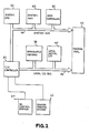
- Fig. 1 there is shown a highly simplified view of a machine tool, in this case a lathe, which will illustrate the use of safe zones.
- the CNC, the driving motors and other required elements of an operating machine tool are not shown in this figure.
- the machine includes a bed 10 upon which is mounted a frame 12 supporting a workpiece holding mechanism or chuck 14.
- the chuck 14 includes jaws 16 which can be tightened upon a workpiece 18 to hold it in position and, in the case of the illustrated lathe, provide the connection to the driving motors which enables the workpiece to be rotated for machining. While one end of the workpiece 18 is held within the jaws 16, a second end is held against a tailstock 20 and pinned in place by a center 22 held in a center holder 40.
- the tailstock 20 is also attached to the machine bed 10.
- a tool holding mechanism 24 is also mounted on the machine tool bed 10.
- the tool holding mechanism 24 includes a base 26 which allows the mechanism 24 to move in parallel with the lengthwise axis of the workpiece 18 and also to move in a direction perpendicular to the workpiece 18.
- a cutting tool 28 and tool base 30 are mounted in the tool holding mechanism 24.
- the base 30 is connected to the mechanism 24 in such a manner that it can be raised and lowered so as to bring the cutting tool 28 into contact with the workpiece 18.
- the axis of motion parallel to the lengthwise axis of the workpiece will be referred to as the Z axis
- the vertical axis will be referred to as the Y axis
- the axis moving in and out of the paper with respect to the viewer will be referred to as the X axis.
- any move in the Z axis direction towards the frame 20 may also result in the tool 28 or tool holder 30 or mechanism 24 coming into contact with some portion of the tailstock 20.
- a zone 32 is defined around the chuck 14.
- An additional zone 34 is also formed around the jaws 16.
- a zone 36 is defined around the center 22 and a zone 38 is defined around the center holder 40.
- An additional zone 42 is also defined about a portion of the tailstock 20. Since in a lathe of the type illustrated, the position of the tool 28 in the X axis is normally fixed, the zones need only be two dimensional for this application. Accordingly, the computation of interference points need only be done with respect to lines rather than planes. However, in a milling machine or robot arm operation, the zones would more likely be three-dimensional.
- the present invention is particularly adapted for use with a computer numerical control (CNC) in which the positioning of the cutting tool 28 with respect to the workpiece 18 is defined by a part program operating within the CNC.
- CNC computer numerical control
- part programs are divided into command moves or work statements wherein each block of information within a part program defines a unidirectional movement of the machine cutting tool 28 with respect to the workpiece 18.
- the CNC determines whether that move will intersect any of the protected zones on the machine tool working area.
- the CNC will determine whether the machine tool 28 during a prescribed movement-would intersect the zones 32, 34, 36, 38 and 42. If any of the zones would be intersected by the command move, the part program would be stopped and operation of the machine tool inhibited so that an operator could be alerted and take appropriate action.
- the cutting tool 28 may be of primary concern, it is also possible that a corner 44 of the tool base 30 might also come in contact with the chuck 14 or chuck jaws 16.
- the point 44 may be defined as an additional monitored point for which the CNC would also have to determine whether that point intersected any of the defined safe zones for any particular commanded move.
- the Mark Century 2000 CNC is a microprocessor based control unit employing Intel 8086 and 8087 microprocessors.
- the hardware architecture for the Mark Century 2000 CNC is shown in Fig. 2.
- the system central processing unit (CPU) 46 performs processing operations for the system and contains the Intel 8086 and 8087 microprocessors.
- the system- dynamic ram 48 (ramdom access memory) contains read- write memory for the system and is coupled to the system CPU and other functional portions of the system through a.system bus 50.
- An axis controller 52 connected to the bus 50 provides several control functions for each driven axis of a machine tool 53.
- the axis controller 52 contains it own microprocessor which serves as a front end processor to interface a coordinated group of axes to the system bus while other processors on the controller perform computations for the control axis.
- An input-output (I/O) controller 54 coordinates system bus I/O operations and serves to connect the system bus to a local I/O bus 56.
- the local I/O bus 56 connects the system to a non-volatile memory 58 in which the part programs and all system data which must be preserved are stored.
- the local I/O bus 56 is also connected to a local digital I/O 60 which is functionally associated with a machine control station 62.
- the local digital I/O 60 generates digitized actuator control signals and monitors the status of contact inputs.
- An NC control station 64 is also connected to the I/O controller 54.
- the NC control station 64 serves as a front panel to machine tool operators, part programmers and designers.
- the machine control station 62 is a control panel from which a machine tool operator can perform manual operations and control the execution of part programs.
- the CNC illustrated in Fig. 2 operates under control of the system CPU 46 executing programs resident in the system ram 48.
- Part programs may be input from an external device such as a paper tape or cassette reader (not shown) through the I/O controller 54 or through a keyboard on the NC control station 64. Any part program which is input to the system is stored by the I/O controller 54 into non-volatile memory 58.
- the system CPU 46 directs the execution of other part programs through the I/O controller 54 and the axis controller 52.
- Part programmed axis commands are executed through the axis controller 52 which is connected to the machine tool 53.
- the machine tool 53 contains axis feed drives which are under control of the axis controller
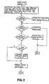
- Fig. 3 there is shown a flow chart illustrating broadly the improved method of operation as applied to a lathe of the type illustrated in Fig. 1.
- Safe zone checking is initiated each time that a block of data is processed by the CNC system. Before any move is initiated, the program verifies that no zones will be violated by the move.
- the subject of safe or protective zones can be divided into three distinct areas:
- the inventive method utilized in the present invention prevents a programmed or internally generated move from becoming active if it is determined on a predictive basis that it would exceed the bounds of a defined safe zone. It should be noted that the actual location of-a-tool tip must also be determined before the tool tip path can be located. The tool tip position will be modified by tool offsets, tool nose radius compensation, presets, offsets and reference zero presets.
- the safe zone checking module is called for each block of information within a part program and also for each manual move generated from the control station 62.
- a block of information may define either a move, a zone definition change or some other instruction. If the information block is merely a definition CHANGE IN A ZONE, tne safe zone checking module is only called upon to establish the new desired safe zone definitions. If the command block is for a move, then the module must determine whether that move will intersect a safe zone which was previously established. Since the primary interference concern in a lathe is with the chuck, the first step is to determine the chuck dimensions.
- the "HAS CHUCK BEEN CHANGED" step determines if the chuck dimensions have been changed and, if so, branches to DEFINE NEW ZONE.
- the program determines whether the command block is a move block or a definition change. If it is merely a definition change, the program will recognize a condition change and branch to establish the new safe zone (ESTABLISH SAFE ZONE) followed by an exit of the program. If the command block is not a zone condition change, then it could be a move command and the method then requires a check to determine whether there are additional monitoring points J (ADD MONITORING POINTS).
- the command block is a definitional block rather than a move block and the program will then branch to CREATE A NEW ZONE RECORD in which step the new monitoring points are identified. If additional monitoring points are not being added, then the command block must be a move block and the next step is to determine whether any monitored zones are active (IS A ZONE ACTIVE) since it is possible to disable safe zones via part program input. If any zone is active, the program performs a safe zone check (PERFORM LATHE SAFE ZONE CHECK) and calculates whether the move will intersect a safe zone. After all checks have been completed, the program updates all the active safe zones and exits. If no zones are active, updates are unnecessary and the data is merely "rolled" so as to be available for the next command block.
- a safe zone check PERFORM LATHE SAFE ZONE CHECK
- Figs. 4 through 11 expand upon the functions identified in the flow chart of Fig. 3.
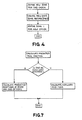
- Fig. 4 the step entitled DEFINE NEW ZONE FOR THIS CHUCK is shown in greater detail.
- a new safe zone record must be created in memory (CREATE NEW SAFE ZONE RECORD).
- the creation of a new safe zone record will be further described in Fig. 5._ Once a safe zone record has been established, the new chuck safe zone is moved into the zone one definition
- the program must first determine whether or not a zone definition already exists for the required safe zone. If a zone definition does exist, the zone data is copied into a new record location. The program then moves the pointer to the active safe zone location. If the zone definition does not exist, a new record must be created and values initialized either in accordance with the information programmed from the NC control station 64 or from information supplied with the part program. Once the new record is created, the pointer is updated to point to the active safe zone information.
- the safe zone check determines first whether safe zone checking has been enabled. If checking has not been enabled, the program immediately exits. Otherwise, the program evaluates the commanded move by calculating the predicted tool path and the start and end points of the move for the tool tip. Once the start and end points and predicted tool path are calculated, the program next checks if a new zone definition exists. If a new zone has been defined, there is a possibility that the start point of the move may already violate a zone. Such may occur, for example, on - initial startup of the system. Thus, the programmed method checks a safe zone violation at the current tool position.
- a zone is violated, an error signal is generated and the operation of the machine tool is inhibited. If no new zone definition occurs, the current position check is skipped and the program checks to see if a zone would be intersected by the commanded move. If the move will violate a.zone, an error is signalled and machine operation is inhibited. If the commanded move does not violate a zone, the program next determines whether there are additional monitoring points other than the tool tip which must be checked. The additional monitoring points are checked in essentially the same manner as the tool tip. The start point and intersection point with the defined safe zones are checked to determine if they will violate a safe zone. If any checks result in a violation of a safe zone, an error signal is generated and operation of the machine tool is inhibited. If no violations are detected, the program exits and allows the commanded move to be processed.
- a flow chart for the step entitled CALCULATE PREDICTED TOOL POSITION is shown in Fig. 7.
- the first check is to determine whether the commanded move is an auxilliary or primary axis move.
- an auxiliary axis is defined as a non-contouring axis and non-spindle axis, e.g., it may be a tool changer which is rotating or a table rotating to bring a workpiece into position.
- the programed method performs essentially the same safe zone checks as for a primary axis.
- For a primary axis move the predicted position at the start and the end of the move are determined. The exact details of the calculations are shown in detail in the program attached hereto as a microfiche appendix.
- Fig. 8 there is shown an expanded flow chart for the step CHECK IF SAFE ZONES ARE VIOLATED BY CURRENT POSITION of a monitored point.
- the first check for any safe zone is to determine whether or not that safe zone has been enabled for this particular move. If the safe zone is enabled, the calculations are performed. Otherwise, that zone is skipped and the next zone to be checked is processed.
- the programed method determines whether the zone type is a no-exit or a no-entry zone. If the zone type is a no-entry zone, then a calculation must be performed to determine if the actual position at the start point of the move is inside the safe zone.
- the program checks to determine if all zones have been completed and, if so, exits to the main program. If the zone type is determined to be a no-exit type of zone, then the checking will determine if the start point is outside the zone and therefore already in violation of the safe zone dimensions.
- Fig. 9 illustrates the method for determining if the safe zone is intersected by a commanded move. Again the first check determines whether or not the particular zone being checked is enabled at this time. Assuming that the zone has been enabled, the potential relative movement between the tool and workpiece can be a circular arc or a linear move. If a circular arc is programmed, a unique calculation is required to determine if the arc intersects the zone. A different calculation is required to determine if a linear move, i.e., straight line, will intersect the zone. Both of these calculations are disclosed in detail in the microfiche appendix.
- the programmed method evaluates whether or not the move is a JOG move, i.e., a manually forced move. Since it may be desirable to advance a tool to a location adjacent a safe zone, a-JOG move is permitted to continue up to the point at which it actually intersects a safe zone. In processing the JOG move, however, the program actually calculates the closest intersection point to the JOG move and allows an operator to JOG only to that closest point, i.e., rather than permit the commanded move to be processed, the distance to the closest intersection point is substituted for the commanded move distance so that the actual move is truncated at the zone intersection point.
- a JOG move i.e., a manually forced move. Since it may be desirable to advance a tool to a location adjacent a safe zone, a-JOG move is permitted to continue up to the point at which it actually intersects a safe zone.
- the program actually calculates the closest intersection point to the JOG move and allows an operator to JOG only to that closest point,
Landscapes
- Engineering & Computer Science (AREA)
- Human Computer Interaction (AREA)
- Manufacturing & Machinery (AREA)
- Physics & Mathematics (AREA)
- General Physics & Mathematics (AREA)
- Automation & Control Theory (AREA)
- Numerical Control (AREA)
- Safety Devices In Control Systems (AREA)
Applications Claiming Priority (2)
| Application Number | Priority Date | Filing Date | Title |
|---|---|---|---|
| US415093 | 1982-09-07 | ||
| US06/415,093 US4489377A (en) | 1982-09-07 | 1982-09-07 | Method for preventing machine component interference |
Publications (3)
| Publication Number | Publication Date |
|---|---|
| EP0104409A2 true EP0104409A2 (de) | 1984-04-04 |
| EP0104409A3 EP0104409A3 (en) | 1985-10-30 |
| EP0104409B1 EP0104409B1 (de) | 1989-11-15 |
Family
ID=23644353
Family Applications (1)
| Application Number | Title | Priority Date | Filing Date |
|---|---|---|---|
| EP83108160A Expired EP0104409B1 (de) | 1982-09-07 | 1983-08-18 | Verfahren zum Feststellen von Sicherheitszonen in einer numerisch gesteuerten Maschine |
Country Status (5)
| Country | Link |
|---|---|
| US (1) | US4489377A (de) |
| EP (1) | EP0104409B1 (de) |
| JP (1) | JPS5971502A (de) |
| DE (1) | DE3380857D1 (de) |
| IL (1) | IL68869A (de) |
Cited By (7)
| Publication number | Priority date | Publication date | Assignee | Title |
|---|---|---|---|---|
| EP0113682A3 (en) * | 1983-01-11 | 1986-08-27 | Mitsubishi Denki Kabushiki Kaisha | Numerical control system and method of displaying images therein |
| EP0131056A4 (de) * | 1982-12-22 | 1987-03-12 | Fanuc Ltd | Verfahren zum steuern der profilierung. |
| WO1995008142A1 (de) * | 1993-09-13 | 1995-03-23 | Grundig Aktiengesellschaft | Verfahren zur zweidimensionalen arbeitsraumkonturermittlung für drehmaschinen |
| EP0620079A4 (en) * | 1992-10-06 | 1996-05-29 | Fanuc Ltd | Method for checking machining program for numerical controller. |
| EP2402114A1 (de) | 2010-07-02 | 2012-01-04 | Ott-Jakob Spanntechnik GmbH | Vorrichtung und Verfahren zum Schutz einer Arbeitsspindel |
| CN119151085A (zh) * | 2024-11-18 | 2024-12-17 | 南兴装备股份有限公司 | 一种基于遗传算法确定工件钻孔顺序的方法及系统 |
| EP4107080B1 (de) * | 2020-02-20 | 2025-04-09 | G.D Societa' Per Azioni | Verfahren zum selektiven management der alarme einer automatischen maschine zur herstellung oder verpackung von verbraucherartikeln |
Families Citing this family (30)
| Publication number | Priority date | Publication date | Assignee | Title |
|---|---|---|---|---|
| JPS5968003A (ja) * | 1982-10-13 | 1984-04-17 | Toyoda Mach Works Ltd | 数値制御工作機械の非常機械原点復帰装置 |
| JPS59124544A (ja) * | 1982-12-29 | 1984-07-18 | Mitsubishi Electric Corp | 数値制御装置の加工方式 |
| JPS59214539A (ja) * | 1983-05-17 | 1984-12-04 | Fanuc Ltd | 工具干渉チエツク方法 |
| JPS60502A (ja) * | 1983-06-17 | 1985-01-05 | Fanuc Ltd | 描画によるストアドストロ−クリミツトチエツク付数値制御装置 |
| US4799408A (en) * | 1985-02-21 | 1989-01-24 | General Electric Company | Automatic cutting bit recovery |
| US5157595A (en) * | 1985-07-19 | 1992-10-20 | El Paso Technologies, Company | Distributed logic control system and method |
| US4758961A (en) * | 1986-07-10 | 1988-07-19 | Yamazaki Machinery Works, Ltd. | Tool move control method and apparatus for preventing tool interference with an object. |
| US4764873A (en) * | 1987-02-13 | 1988-08-16 | Dalmo Victor, Inc., Div. Of The Singer Company | Path blockage determination system and method |
| US4979121A (en) * | 1987-09-25 | 1990-12-18 | Yamazaki Mazak Corporation | Control method and apparatus for controlling machining operations in a machine tool having a plurality of coordinate systems |
| JPH01152508A (ja) * | 1987-12-10 | 1989-06-15 | Fanuc Ltd | Cnc制御方式 |
| DE3809630C1 (de) * | 1988-03-22 | 1989-05-18 | Duerkopp Systemtechnik Gmbh, 4800 Bielefeld, De | |
| US5122966A (en) * | 1989-09-18 | 1992-06-16 | Northern Research & Engineering | Computer generated tool path interference check method |
| JP2974183B2 (ja) * | 1991-11-07 | 1999-11-08 | オークマ株式会社 | 数値制御工作機械における干渉チェック装置 |
| EP0766154B1 (de) * | 1992-12-28 | 2000-03-29 | Mitsubishi Denki Kabushiki Kaisha | Numerisch gesteuerte Werkzeugmaschine und Verfahren |
| US5526272A (en) * | 1993-01-18 | 1996-06-11 | Canon Kabushiki Kaisha | Data preparation device and method for preparing data for machining work |
| US5594309A (en) * | 1994-06-15 | 1997-01-14 | Iowa State University Research Foundation, Inc. | Robot control scheme |
| JP3339821B2 (ja) * | 1998-06-29 | 2002-10-28 | 新キャタピラー三菱株式会社 | 作業機械のロック方法およびそのロック装置 |
| DE10330831A1 (de) * | 2003-07-08 | 2005-02-10 | Mtu Aero Engines Gmbh | Fräsverfahren zur Fertigung von Bauteilen |
| JP4362095B2 (ja) * | 2004-08-20 | 2009-11-11 | オークマ株式会社 | 数値制御装置 |
| US8219245B2 (en) * | 2006-05-15 | 2012-07-10 | Kuka Roboter Gmbh | Articulated arm robot |
| DE102006046759B4 (de) * | 2006-09-29 | 2018-05-17 | Abb Ag | Verfahren zur Erhöhung der Sicherheit beim Betrieb eines Roboters |
| US9459616B2 (en) * | 2007-08-03 | 2016-10-04 | Hurco Companies, Inc. | Universal conversational programming for machine tool systems |
| US8844104B2 (en) * | 2009-04-22 | 2014-09-30 | Hurco Companies, Inc. | Multi-zone machine tool system |
| DE102007059568A1 (de) * | 2007-12-11 | 2009-06-18 | Mtu Aero Engines Gmbh | Tauchfräsverfahren |
| US20100023157A1 (en) * | 2008-07-28 | 2010-01-28 | Steven Michael Burgess | Methods and systems for fabricating a component |
| CN102667650B (zh) * | 2009-12-15 | 2013-09-25 | 山崎马扎克公司 | 数控机床 |
| JP5813058B2 (ja) * | 2013-07-02 | 2015-11-17 | ファナック株式会社 | 複合形固定サイクルの開始点経路短縮機能を有する数値制御装置 |
| JP6013690B2 (ja) * | 2014-09-18 | 2016-10-25 | ファナック株式会社 | 加工再開位置へのアプローチを行う数値制御装置 |
| TWI656942B (zh) * | 2018-01-12 | 2019-04-21 | 財團法人工業技術研究院 | 工具機防碰撞方法及工具機防碰撞系統 |
| ES3063628T3 (en) * | 2018-06-06 | 2026-04-17 | Agie Charmilles Sa | Collision protection method |
Family Cites Families (5)
| Publication number | Priority date | Publication date | Assignee | Title |
|---|---|---|---|---|
| JPS5333484A (en) * | 1976-09-10 | 1978-03-29 | Okuma Mach Works Ltd | Interference preventive system of machine tool having plurality of movable members |
| JPS5947322B2 (ja) * | 1977-09-14 | 1984-11-19 | 株式会社東芝 | ストロ−クオ−バ−検知方法 |
| JPS5773402A (en) * | 1980-10-23 | 1982-05-08 | Fanuc Ltd | Numerical control system |
| GB2094506B (en) * | 1981-02-05 | 1984-04-18 | Gardner R F | Control of production equipment |
| JPS58163001A (ja) * | 1982-03-23 | 1983-09-27 | Toyoda Mach Works Ltd | 干渉チエツク機能を備えた数値制御装置 |
-
1982
- 1982-09-07 US US06/415,093 patent/US4489377A/en not_active Expired - Fee Related
-
1983
- 1983-06-02 IL IL68869A patent/IL68869A/xx unknown
- 1983-08-18 EP EP83108160A patent/EP0104409B1/de not_active Expired
- 1983-08-18 DE DE8383108160T patent/DE3380857D1/de not_active Expired
- 1983-09-07 JP JP58163380A patent/JPS5971502A/ja active Pending
Cited By (11)
| Publication number | Priority date | Publication date | Assignee | Title |
|---|---|---|---|---|
| EP0131056A4 (de) * | 1982-12-22 | 1987-03-12 | Fanuc Ltd | Verfahren zum steuern der profilierung. |
| EP0113682A3 (en) * | 1983-01-11 | 1986-08-27 | Mitsubishi Denki Kabushiki Kaisha | Numerical control system and method of displaying images therein |
| EP0620079A4 (en) * | 1992-10-06 | 1996-05-29 | Fanuc Ltd | Method for checking machining program for numerical controller. |
| US6157869A (en) * | 1992-10-06 | 2000-12-05 | Fanuc Ltd. | Machining program checking method for a numerical control device |
| WO1995008142A1 (de) * | 1993-09-13 | 1995-03-23 | Grundig Aktiengesellschaft | Verfahren zur zweidimensionalen arbeitsraumkonturermittlung für drehmaschinen |
| US5654618A (en) * | 1993-09-13 | 1997-08-05 | Dr. Johannes Heidenhain Gmbh | Process for the two-dimensional determination of a work-area contour for lathes |
| EP2402114A1 (de) | 2010-07-02 | 2012-01-04 | Ott-Jakob Spanntechnik GmbH | Vorrichtung und Verfahren zum Schutz einer Arbeitsspindel |
| DE102010025900A1 (de) | 2010-07-02 | 2012-01-05 | Ott-Jakob Spanntechnik Gmbh | Vorrichtung zum Schutz einer Arbeitsspindel |
| US9089942B2 (en) | 2010-07-02 | 2015-07-28 | Ott-Jakob Spanntechnik Gmbh | Device for protecting a work spindle |
| EP4107080B1 (de) * | 2020-02-20 | 2025-04-09 | G.D Societa' Per Azioni | Verfahren zum selektiven management der alarme einer automatischen maschine zur herstellung oder verpackung von verbraucherartikeln |
| CN119151085A (zh) * | 2024-11-18 | 2024-12-17 | 南兴装备股份有限公司 | 一种基于遗传算法确定工件钻孔顺序的方法及系统 |
Also Published As
| Publication number | Publication date |
|---|---|
| DE3380857D1 (en) | 1989-12-21 |
| EP0104409A3 (en) | 1985-10-30 |
| IL68869A (en) | 1986-10-31 |
| US4489377A (en) | 1984-12-18 |
| JPS5971502A (ja) | 1984-04-23 |
| EP0104409B1 (de) | 1989-11-15 |
Similar Documents
| Publication | Publication Date | Title |
|---|---|---|
| US4489377A (en) | Method for preventing machine component interference | |
| KR950000839B1 (ko) | 이상정지기능을 구비한 수치 제어공작기계 | |
| EP0027317B1 (de) | Taktfolgesteuerungssystem für numerisch gesteuerte Werkzeugmaschine | |
| US20190271965A1 (en) | Numerical controller and numerical control method | |
| US4513380A (en) | Method of tool recovery in threadcutting apparatus | |
| KR0180953B1 (ko) | 수치제어 공작기계의 주축법선방향 제어방법 및 장치 | |
| JPH0611458B2 (ja) | 工具形状表示装置 | |
| JPH11170117A (ja) | 工作機械の移動軸の制御方法及び装置 | |
| JP2000284817A (ja) | 共通経路上の2つの可動体を同時制御する数値制御装置 | |
| US20180364681A1 (en) | Numerical controller | |
| US10996655B2 (en) | Numerical controller | |
| JPH08263115A (ja) | Nc工作機械における干渉回避方法 | |
| CN101893870B (zh) | 四轴加工机用数值控制装置 | |
| US5060163A (en) | Programming apparatus for lathes | |
| JP2624174B2 (ja) | 数値制御装置の自動運転方式 | |
| JPH08194516A (ja) | パンチプレスの干渉防止方式 | |
| JP4066178B2 (ja) | 工作機械及びその異常検査方法 | |
| JPH11242511A (ja) | 共通経路上の2つの可動体を同時制御する数値制御装置 | |
| JPH08150540A (ja) | 工作機械の干渉防止装置 | |
| JPH0360618B2 (de) | ||
| EP0380685A1 (de) | Numerisches steuersystem | |
| JPH0363761B2 (de) | ||
| JPH05237741A (ja) | Ncデータ作成方法 | |
| JPS63312042A (ja) | 数値制御自動旋盤における工具干渉防止装置 | |
| KR830002110B1 (ko) | 수치제어 공작 기계의 시이퀀스 제어방식 |
Legal Events
| Date | Code | Title | Description |
|---|---|---|---|
| PUAI | Public reference made under article 153(3) epc to a published international application that has entered the european phase |
Free format text: ORIGINAL CODE: 0009012 |
|
| AK | Designated contracting states |
Designated state(s): DE FR GB IT |
|
| PUAL | Search report despatched |
Free format text: ORIGINAL CODE: 0009013 |
|
| AK | Designated contracting states |
Designated state(s): DE FR GB IT |
|
| 17P | Request for examination filed |
Effective date: 19860423 |
|
| 17Q | First examination report despatched |
Effective date: 19871103 |
|
| GRAA | (expected) grant |
Free format text: ORIGINAL CODE: 0009210 |
|
| AK | Designated contracting states |
Kind code of ref document: B1 Designated state(s): DE FR GB IT |
|
| ET | Fr: translation filed | ||
| REF | Corresponds to: |
Ref document number: 3380857 Country of ref document: DE Date of ref document: 19891221 |
|
| ITF | It: translation for a ep patent filed | ||
| PGFP | Annual fee paid to national office [announced via postgrant information from national office to epo] |
Ref country code: GB Payment date: 19900626 Year of fee payment: 8 |
|
| PLBI | Opposition filed |
Free format text: ORIGINAL CODE: 0009260 |
|
| PGFP | Annual fee paid to national office [announced via postgrant information from national office to epo] |
Ref country code: FR Payment date: 19900814 Year of fee payment: 8 |
|
| ITTA | It: last paid annual fee | ||
| PGFP | Annual fee paid to national office [announced via postgrant information from national office to epo] |
Ref country code: DE Payment date: 19900906 Year of fee payment: 8 |
|
| 26 | Opposition filed |
Opponent name: SIEMENS AKTIENGESELLSCHAFT, BERLIN UND MUENCHEN Effective date: 19900731 |
|
| PG25 | Lapsed in a contracting state [announced via postgrant information from national office to epo] |
Ref country code: GB Effective date: 19910818 |
|
| GBPC | Gb: european patent ceased through non-payment of renewal fee | ||
| PG25 | Lapsed in a contracting state [announced via postgrant information from national office to epo] |
Ref country code: FR Effective date: 19920430 |
|
| PG25 | Lapsed in a contracting state [announced via postgrant information from national office to epo] |
Ref country code: DE Effective date: 19920501 |
|
| REG | Reference to a national code |
Ref country code: FR Ref legal event code: ST |
|
| RDAG | Patent revoked |
Free format text: ORIGINAL CODE: 0009271 |
|
| STAA | Information on the status of an ep patent application or granted ep patent |
Free format text: STATUS: PATENT REVOKED |
|
| 27W | Patent revoked |
Effective date: 19921003 |