EP0105068B1 - Elektrische Schweissmuffe aus Kunststoff und Verfahren zu deren Herstellung - Google Patents
Elektrische Schweissmuffe aus Kunststoff und Verfahren zu deren Herstellung Download PDFInfo
- Publication number
- EP0105068B1 EP0105068B1 EP82401816A EP82401816A EP0105068B1 EP 0105068 B1 EP0105068 B1 EP 0105068B1 EP 82401816 A EP82401816 A EP 82401816A EP 82401816 A EP82401816 A EP 82401816A EP 0105068 B1 EP0105068 B1 EP 0105068B1
- Authority
- EP
- European Patent Office
- Prior art keywords
- wire
- resistant
- resistant wire
- mandrel
- envelope
- Prior art date
- Legal status (The legal status is an assumption and is not a legal conclusion. Google has not performed a legal analysis and makes no representation as to the accuracy of the status listed.)
- Expired
Links
- 238000004519 manufacturing process Methods 0.000 title claims description 11
- 238000000034 method Methods 0.000 title description 10
- 238000004023 plastic welding Methods 0.000 title 1
- 238000004804 winding Methods 0.000 claims description 27
- 239000012815 thermoplastic material Substances 0.000 claims description 21
- 238000003466 welding Methods 0.000 claims description 12
- 238000010438 heat treatment Methods 0.000 claims description 10
- 229920001169 thermoplastic Polymers 0.000 claims description 10
- 239000004416 thermosoftening plastic Substances 0.000 claims description 10
- 239000000463 material Substances 0.000 claims description 7
- 230000000694 effects Effects 0.000 claims description 6
- 229910000881 Cu alloy Inorganic materials 0.000 claims description 3
- 229920003023 plastic Polymers 0.000 claims description 3
- 239000004033 plastic Substances 0.000 claims description 3
- YOCUPQPZWBBYIX-UHFFFAOYSA-N copper nickel Chemical compound [Ni].[Cu] YOCUPQPZWBBYIX-UHFFFAOYSA-N 0.000 claims description 2
- 238000001746 injection moulding Methods 0.000 claims description 2
- 229920001903 high density polyethylene Polymers 0.000 description 4
- 239000004700 high-density polyethylene Substances 0.000 description 4
- 238000002347 injection Methods 0.000 description 4
- 239000007924 injection Substances 0.000 description 4
- 239000004800 polyvinyl chloride Substances 0.000 description 4
- 239000004698 Polyethylene Substances 0.000 description 3
- 239000002184 metal Substances 0.000 description 3
- 229910052751 metal Inorganic materials 0.000 description 3
- -1 polyethylene Polymers 0.000 description 3
- 229920000573 polyethylene Polymers 0.000 description 3
- 229920000915 polyvinyl chloride Polymers 0.000 description 3
- 229920005989 resin Polymers 0.000 description 3
- 239000011347 resin Substances 0.000 description 3
- PXHVJJICTQNCMI-UHFFFAOYSA-N Nickel Chemical compound [Ni] PXHVJJICTQNCMI-UHFFFAOYSA-N 0.000 description 2
- 238000009826 distribution Methods 0.000 description 2
- 229920005992 thermoplastic resin Polymers 0.000 description 2
- 229910000990 Ni alloy Inorganic materials 0.000 description 1
- 230000015556 catabolic process Effects 0.000 description 1
- 238000007796 conventional method Methods 0.000 description 1
- 238000001816 cooling Methods 0.000 description 1
- 230000007797 corrosion Effects 0.000 description 1
- 238000005260 corrosion Methods 0.000 description 1
- 230000007547 defect Effects 0.000 description 1
- 238000006731 degradation reaction Methods 0.000 description 1
- 239000003000 extruded plastic Substances 0.000 description 1
- 230000002349 favourable effect Effects 0.000 description 1
- 239000012530 fluid Substances 0.000 description 1
- 239000007789 gas Substances 0.000 description 1
- 238000011065 in-situ storage Methods 0.000 description 1
- 239000007788 liquid Substances 0.000 description 1
- 239000000155 melt Substances 0.000 description 1
- 239000007769 metal material Substances 0.000 description 1
- 238000013021 overheating Methods 0.000 description 1
- 229920006255 plastic film Polymers 0.000 description 1
- 229920000098 polyolefin Polymers 0.000 description 1
- 239000004810 polytetrafluoroethylene Substances 0.000 description 1
- 229920001343 polytetrafluoroethylene Polymers 0.000 description 1
- 238000007789 sealing Methods 0.000 description 1
- 230000035939 shock Effects 0.000 description 1
- 238000005507 spraying Methods 0.000 description 1
- 239000000126 substance Substances 0.000 description 1
- XLYOFNOQVPJJNP-UHFFFAOYSA-N water Substances O XLYOFNOQVPJJNP-UHFFFAOYSA-N 0.000 description 1
Images

Classifications
-
- B—PERFORMING OPERATIONS; TRANSPORTING
- B29—WORKING OF PLASTICS; WORKING OF SUBSTANCES IN A PLASTIC STATE IN GENERAL
- B29D—PRODUCING PARTICULAR ARTICLES FROM PLASTICS OR FROM SUBSTANCES IN A PLASTIC STATE
- B29D23/00—Producing tubular articles
- B29D23/001—Pipes; Pipe joints
- B29D23/003—Pipe joints, e.g. straight joints
- B29D23/005—Pipe joints, e.g. straight joints provided with electrical wiring
-
- B—PERFORMING OPERATIONS; TRANSPORTING
- B29—WORKING OF PLASTICS; WORKING OF SUBSTANCES IN A PLASTIC STATE IN GENERAL
- B29C—SHAPING OR JOINING OF PLASTICS; SHAPING OF MATERIAL IN A PLASTIC STATE, NOT OTHERWISE PROVIDED FOR; AFTER-TREATMENT OF THE SHAPED PRODUCTS, e.g. REPAIRING
- B29C65/00—Joining or sealing of preformed parts, e.g. welding of plastics materials; Apparatus therefor
- B29C65/02—Joining or sealing of preformed parts, e.g. welding of plastics materials; Apparatus therefor by heating, with or without pressure
- B29C65/34—Joining or sealing of preformed parts, e.g. welding of plastics materials; Apparatus therefor by heating, with or without pressure using heated elements which remain in the joint, e.g. "verlorenes Schweisselement"
- B29C65/3404—Joining or sealing of preformed parts, e.g. welding of plastics materials; Apparatus therefor by heating, with or without pressure using heated elements which remain in the joint, e.g. "verlorenes Schweisselement" characterised by the type of heated elements which remain in the joint
- B29C65/342—Joining or sealing of preformed parts, e.g. welding of plastics materials; Apparatus therefor by heating, with or without pressure using heated elements which remain in the joint, e.g. "verlorenes Schweisselement" characterised by the type of heated elements which remain in the joint comprising at least a single wire, e.g. in the form of a winding
-
- B—PERFORMING OPERATIONS; TRANSPORTING
- B29—WORKING OF PLASTICS; WORKING OF SUBSTANCES IN A PLASTIC STATE IN GENERAL
- B29C—SHAPING OR JOINING OF PLASTICS; SHAPING OF MATERIAL IN A PLASTIC STATE, NOT OTHERWISE PROVIDED FOR; AFTER-TREATMENT OF THE SHAPED PRODUCTS, e.g. REPAIRING
- B29C65/00—Joining or sealing of preformed parts, e.g. welding of plastics materials; Apparatus therefor
- B29C65/02—Joining or sealing of preformed parts, e.g. welding of plastics materials; Apparatus therefor by heating, with or without pressure
- B29C65/34—Joining or sealing of preformed parts, e.g. welding of plastics materials; Apparatus therefor by heating, with or without pressure using heated elements which remain in the joint, e.g. "verlorenes Schweisselement"
- B29C65/3472—Joining or sealing of preformed parts, e.g. welding of plastics materials; Apparatus therefor by heating, with or without pressure using heated elements which remain in the joint, e.g. "verlorenes Schweisselement" characterised by the composition of the heated elements which remain in the joint
- B29C65/3476—Joining or sealing of preformed parts, e.g. welding of plastics materials; Apparatus therefor by heating, with or without pressure using heated elements which remain in the joint, e.g. "verlorenes Schweisselement" characterised by the composition of the heated elements which remain in the joint being metallic
- B29C65/348—Joining or sealing of preformed parts, e.g. welding of plastics materials; Apparatus therefor by heating, with or without pressure using heated elements which remain in the joint, e.g. "verlorenes Schweisselement" characterised by the composition of the heated elements which remain in the joint being metallic with a polymer coating
-
- B—PERFORMING OPERATIONS; TRANSPORTING
- B29—WORKING OF PLASTICS; WORKING OF SUBSTANCES IN A PLASTIC STATE IN GENERAL
- B29C—SHAPING OR JOINING OF PLASTICS; SHAPING OF MATERIAL IN A PLASTIC STATE, NOT OTHERWISE PROVIDED FOR; AFTER-TREATMENT OF THE SHAPED PRODUCTS, e.g. REPAIRING
- B29C66/00—General aspects of processes or apparatus for joining preformed parts
- B29C66/01—General aspects dealing with the joint area or with the area to be joined
- B29C66/05—Particular design of joint configurations
- B29C66/10—Particular design of joint configurations particular design of the joint cross-sections
- B29C66/12—Joint cross-sections combining only two joint-segments; Tongue and groove joints; Tenon and mortise joints; Stepped joint cross-sections
- B29C66/122—Joint cross-sections combining only two joint-segments, i.e. one of the parts to be joined comprising only two joint-segments in the joint cross-section
- B29C66/1222—Joint cross-sections combining only two joint-segments, i.e. one of the parts to be joined comprising only two joint-segments in the joint cross-section comprising at least a lapped joint-segment
-
- B—PERFORMING OPERATIONS; TRANSPORTING
- B29—WORKING OF PLASTICS; WORKING OF SUBSTANCES IN A PLASTIC STATE IN GENERAL
- B29C—SHAPING OR JOINING OF PLASTICS; SHAPING OF MATERIAL IN A PLASTIC STATE, NOT OTHERWISE PROVIDED FOR; AFTER-TREATMENT OF THE SHAPED PRODUCTS, e.g. REPAIRING
- B29C66/00—General aspects of processes or apparatus for joining preformed parts
- B29C66/01—General aspects dealing with the joint area or with the area to be joined
- B29C66/05—Particular design of joint configurations
- B29C66/10—Particular design of joint configurations particular design of the joint cross-sections
- B29C66/12—Joint cross-sections combining only two joint-segments; Tongue and groove joints; Tenon and mortise joints; Stepped joint cross-sections
- B29C66/122—Joint cross-sections combining only two joint-segments, i.e. one of the parts to be joined comprising only two joint-segments in the joint cross-section
- B29C66/1224—Joint cross-sections combining only two joint-segments, i.e. one of the parts to be joined comprising only two joint-segments in the joint cross-section comprising at least a butt joint-segment
-
- B—PERFORMING OPERATIONS; TRANSPORTING
- B29—WORKING OF PLASTICS; WORKING OF SUBSTANCES IN A PLASTIC STATE IN GENERAL
- B29C—SHAPING OR JOINING OF PLASTICS; SHAPING OF MATERIAL IN A PLASTIC STATE, NOT OTHERWISE PROVIDED FOR; AFTER-TREATMENT OF THE SHAPED PRODUCTS, e.g. REPAIRING
- B29C66/00—General aspects of processes or apparatus for joining preformed parts
- B29C66/50—General aspects of joining tubular articles; General aspects of joining long products, i.e. bars or profiled elements; General aspects of joining single elements to tubular articles, hollow articles or bars; General aspects of joining several hollow-preforms to form hollow or tubular articles
- B29C66/51—Joining tubular articles, profiled elements or bars; Joining single elements to tubular articles, hollow articles or bars; Joining several hollow-preforms to form hollow or tubular articles
- B29C66/52—Joining tubular articles, bars or profiled elements
- B29C66/522—Joining tubular articles
- B29C66/5221—Joining tubular articles for forming coaxial connections, i.e. the tubular articles to be joined forming a zero angle relative to each other
-
- B—PERFORMING OPERATIONS; TRANSPORTING
- B29—WORKING OF PLASTICS; WORKING OF SUBSTANCES IN A PLASTIC STATE IN GENERAL
- B29C—SHAPING OR JOINING OF PLASTICS; SHAPING OF MATERIAL IN A PLASTIC STATE, NOT OTHERWISE PROVIDED FOR; AFTER-TREATMENT OF THE SHAPED PRODUCTS, e.g. REPAIRING
- B29C66/00—General aspects of processes or apparatus for joining preformed parts
- B29C66/50—General aspects of joining tubular articles; General aspects of joining long products, i.e. bars or profiled elements; General aspects of joining single elements to tubular articles, hollow articles or bars; General aspects of joining several hollow-preforms to form hollow or tubular articles
- B29C66/51—Joining tubular articles, profiled elements or bars; Joining single elements to tubular articles, hollow articles or bars; Joining several hollow-preforms to form hollow or tubular articles
- B29C66/52—Joining tubular articles, bars or profiled elements
- B29C66/522—Joining tubular articles
- B29C66/5229—Joining tubular articles involving the use of a socket
- B29C66/52291—Joining tubular articles involving the use of a socket said socket comprising a stop
- B29C66/52292—Joining tubular articles involving the use of a socket said socket comprising a stop said stop being internal
-
- F—MECHANICAL ENGINEERING; LIGHTING; HEATING; WEAPONS; BLASTING
- F16—ENGINEERING ELEMENTS AND UNITS; GENERAL MEASURES FOR PRODUCING AND MAINTAINING EFFECTIVE FUNCTIONING OF MACHINES OR INSTALLATIONS; THERMAL INSULATION IN GENERAL
- F16L—PIPES; JOINTS OR FITTINGS FOR PIPES; SUPPORTS FOR PIPES, CABLES OR PROTECTIVE TUBING; MEANS FOR THERMAL INSULATION IN GENERAL
- F16L47/00—Connecting arrangements or other fittings specially adapted to be made of plastics or to be used with pipes made of plastics
- F16L47/02—Welded joints; Adhesive joints
- F16L47/03—Welded joints with an electrical resistance incorporated in the joint
-
- B—PERFORMING OPERATIONS; TRANSPORTING
- B29—WORKING OF PLASTICS; WORKING OF SUBSTANCES IN A PLASTIC STATE IN GENERAL
- B29C—SHAPING OR JOINING OF PLASTICS; SHAPING OF MATERIAL IN A PLASTIC STATE, NOT OTHERWISE PROVIDED FOR; AFTER-TREATMENT OF THE SHAPED PRODUCTS, e.g. REPAIRING
- B29C65/00—Joining or sealing of preformed parts, e.g. welding of plastics materials; Apparatus therefor
- B29C65/02—Joining or sealing of preformed parts, e.g. welding of plastics materials; Apparatus therefor by heating, with or without pressure
- B29C65/34—Joining or sealing of preformed parts, e.g. welding of plastics materials; Apparatus therefor by heating, with or without pressure using heated elements which remain in the joint, e.g. "verlorenes Schweisselement"
-
- B—PERFORMING OPERATIONS; TRANSPORTING
- B29—WORKING OF PLASTICS; WORKING OF SUBSTANCES IN A PLASTIC STATE IN GENERAL
- B29C—SHAPING OR JOINING OF PLASTICS; SHAPING OF MATERIAL IN A PLASTIC STATE, NOT OTHERWISE PROVIDED FOR; AFTER-TREATMENT OF THE SHAPED PRODUCTS, e.g. REPAIRING
- B29C66/00—General aspects of processes or apparatus for joining preformed parts
- B29C66/70—General aspects of processes or apparatus for joining preformed parts characterised by the composition, physical properties or the structure of the material of the parts to be joined; Joining with non-plastics material
- B29C66/71—General aspects of processes or apparatus for joining preformed parts characterised by the composition, physical properties or the structure of the material of the parts to be joined; Joining with non-plastics material characterised by the composition of the plastics material of the parts to be joined
Definitions
- thermoplastic is understood to mean in particular polyolefins, such as polyethylene, in particular high density (HDPE) and polyvinyl chloride (PVC); as well as the manufacture of said fittings.
- HDPE high density polyethylene
- PVC polyvinyl chloride
- the sealed assembly of two or more pipes or tubes of thermoplastic material is only obtained by the electrofusion technique.
- This technique consists in heating in-situ and very locally by means of an electrical resistance the contact surfaces of the assembled parts, so as to reach the welding temperature of the two materials; the electrical resistance remaining inserted in the material.
- This type of assembly is done by means of an electrofusion fitting consisting of a cylindrical sleeve made of very thick thermoplastic material.
- This sleeve comprises, in its calibrated internal orifice, a winding of metal wire partially or completely resistant, embedded in the thermoplastic material.
- the ends of the wire are generally fixed to terminals or lugs to ensure good electrical contact with a generator.
- the electrofusion fitting is usually integrated at each end, either of a straight fitting, or of a tee, or of a crosspiece making it possible to connect, respectively, 2, 3 or 4 thermoplastic tubes together.
- the end of the tube to be connected is cut beforehand in a bevel to facilitate the fitting of the electrofusion fitting; on the other hand, the external surface of the tube in contact with the RES is pickled beforehand to obtain better weldability.
- Said fitting is then presented in the axis of the pipe and engaged on it with an adjusted socket, then the RES is connected to a generator set on the heating program in relation to the diameter of the RES; the welding time is between ten seconds and a few minutes and the cooling time of the order of 20 minutes.
- the electrofusion fitting must meet two essential characteristics, namely perfect sealing and mechanical resistance at least equal to that of the tube.
- the resistant wires are clearly visible inside the sleeve, while being partially embedded in the thermoplastic material.
- the resistant wires are not visible, but embedded in the thermoplastic material.
- French patent 2,111,818, in the name of MAN-NESMAN relates to the production of a thermoplastic sleeve obtained by winding an extruded plastic film on a core provided with the coiled resistant wire.
- the extruded film is wound with a large stretch so as to give the thermoplastic high tensions which contribute to its shrinkage during welding.
- This type of electrofusion sleeve seems more particularly suitable for welding large diameter tubes.
- the electroweldable connection with visible resistant wire has the advantage of bringing the resistant wire into direct contact with the tube to be welded and the connection; during heating by Joule effect, the material of the tube and that of the connector melt at the same time and this constitutes a favorable factor for obtaining a good weld.
- the main defect of this type of connection lies in the fact that the visible turns of the wire are vulnerable and can be moved when the tube fits into the electrofusion fitting. Such an accident leads to rejecting the fitting because generally, the resistant wire cannot be replaced.
- Electrofusion fittings with embedded wire do not have this drawback because the resistant wire is protected; however, they have another drawback which appears all the more when the resistant wire is distant from the wall of the tube to be welded, that is to say when the resistant wire is buried deep in the electrofusion fitting.
- thermoplastic material located between the heating wire and the wall of the tube before this wall is hot and has reached the appropriate temperature to ensure a correct weld between the tube and the fitting.
- thermoplastic material is not very conductive of heat, there is a risk of overheating, which leads to its thermal degradation and affects its weldability.
- EP-A-036 963 also discloses an electrofusion sleeve at the two ends of which is provided a grade space with a length of at least 1.5 times the thickness of the wall of the sleeve.
- Said sleeve comprises a winding of resistant wire partially adhering to the internal wall of the sleeve; the sheathing of the resistant wire having practically its original shape at least on the inside of the winding. According to the means described, this type of sleeve cannot allow electrowelding under high pressure.
- a heating sleeve was sought which constitutes the best compromise between the need to protect the resistant wire against mechanical shock during the fitting of the tube to be welded and the need to position the resistant wire so that it is practically in contact with the wall of the tube to be welded.
- thermoplastic material has been found which allows satisfactory welds to be produced with almost 100% success.
- the electrofusion fitting into which a cylindrical sleeve of thermoplastic material is inserted comprising in its calibrated interior orifice a winding of resistant metal wire, the ends of which are fixed to terminals or lugs ensuring good contact with a generator, the resistant wire completely coated in the thermoplastic material being close to the surface of the connector, flush with the interior thereof, being covered with an extra-thin thermoplastic film, characterized in that a generator of the said cylindrical resistant wire tangent to the inner surface of the sleeve, and in that a safety space is provided inside said sleeve on each side of the winding of the resistive wire, said space being at least equal to 30% of the length of the winding.
- the resistant wire is therefore practically in contact with the wall of the tube to be welded while being protected during nesting. It has been discovered that the outcrop of the resistant wire inside proves to be a practically necessary condition for obtaining a good weld.
- the electrofusion fitting in which the sleeve is inserted, is designed such that a safety space is provided inside said sleeve on each side of the winding of the resistant wire, the spaces can be equal, their purpose is avoid the possible leakage of the liquid thermoplastic material on each side of the space occupied by the winding of the resistant wire, during welding by Joule effect.
- the resistant wire is a nickel-copper alloy wire whose resistivity is substantially constant whatever the temperature.
- the diameter of the wire is between 0.2 and 2 mm, preferably between 0.30 and 1 mm; the surface of the wire being oxidized so as to make it electrically insulating and thus avoid electrical short circuits in the event that 2 or more wires come into contact.
- the resistant wire is covered by a thermoplastic sheath whose thickness is between 0.1 and 1 mm, preferably between 0.30 and 0.50 mm.
- the sheathed wire is wound with contiguous turns, the winding being either two-wire so as to obtain that the two ends of the resistant wire are on the same side of the winding, or single-wire so as to obtain each end of the resistant wire on each side of the winding.
- the sheathed resistant wire is wound with contiguous turns on an extendable mandrel made of electrically insulating and temperature resistant material.
- the resistant wire wound on the mandrel is brought by the Joule effect, to the softening temperature of the thermoplastic sheath.
- the mandrel is put in extension until a wire generator is in contact with the outer surface of the mandrel; without the need to put the resistance wire itself in extension.
- the assembly After extension, the assembly is allowed to cool to room temperature, then the sleeve obtained is removed from the mandrel.
- this sleeve is inserted into an electro-weldable connector by the conventional technique of overmolding-injection, while providing inside the sleeve, a safety space on either side of the winding of resistant wire.
- Figure 1 is a sectional view of the resistive wire wound on an extendable mandrel.
- Figure 2 is a sectional view of the resistive wire wound on the extendable mandrel after heating of the wire by an electric current and extension of the mandrel.
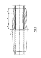
- FIG. 3 represents a finished electrofusion fitting with the tube to be assembled introduced into the electrofusion fitting ready to be welded by Joule effect.
- the resistant wire 1 is a wire 0.8 mm in diameter made of a nickel and copper alloy, the resistivity of which is practically constant whatever the temperature.
- the wire is coated with a sheath 2 of high density polyethylene 0.35 mm thick.
- the sheathed wire is wound, with contiguous turns, on the extendable mandrel 3 provided with a conical part 4 for expansion, the diameter of the PTFE mandrel is approximately 40 mm.
- the winding of the resistant wire is two-wire so as to obtain the two ends of the resistant wire on the same side of the winding.
- the loop, not shown, formed by the wires 8 and 9 is fixed to the mandrel 3 by the screw 5 and the washer 6; the screw 5 is screwed into the threaded orifice 7 of the mandrel 3.
- the ends 10 and 11 of the resistant wire are held on a part, not shown, other than the mandrel 3.
- the ends of the resistant wire are connected to an electric generator adjusted so that the temperature of the resistant wire as well as that of the sheath are brought to the softening zone of high density polyethylene, ie 200 ° C. approximately, this temperature is reached after ten seconds of heating.
- the mandrel 3 is put in extension by pushing the conical core 4 into the mandrel 3 ( Figure 2); the extension of the mandrel 3 is continued until the external surface of the mandrel is practically in contact with a generator of the resistant wire 1 (FIG. 2).
- This sleeve is then inserted into an electrofusion fitting 12 by the conventional overmolding-injection technique.
- the RES is produced in such a way that safety spaces b and c are provided on each side of the space a where the winding of resistant wire is located.
Landscapes
- Engineering & Computer Science (AREA)
- Mechanical Engineering (AREA)
- General Engineering & Computer Science (AREA)
- Branch Pipes, Bends, And The Like (AREA)
- Lining Or Joining Of Plastics Or The Like (AREA)
Claims (5)
Priority Applications (2)
| Application Number | Priority Date | Filing Date | Title |
|---|---|---|---|
| EP82401816A EP0105068B1 (de) | 1982-10-05 | 1982-10-05 | Elektrische Schweissmuffe aus Kunststoff und Verfahren zu deren Herstellung |
| DE8282401816T DE3272031D1 (en) | 1982-10-05 | 1982-10-05 | Electrical plastic welding sleeve and method for its manufacture |
Applications Claiming Priority (1)
| Application Number | Priority Date | Filing Date | Title |
|---|---|---|---|
| EP82401816A EP0105068B1 (de) | 1982-10-05 | 1982-10-05 | Elektrische Schweissmuffe aus Kunststoff und Verfahren zu deren Herstellung |
Publications (2)
| Publication Number | Publication Date |
|---|---|
| EP0105068A1 EP0105068A1 (de) | 1984-04-11 |
| EP0105068B1 true EP0105068B1 (de) | 1986-07-16 |
Family
ID=8189942
Family Applications (1)
| Application Number | Title | Priority Date | Filing Date |
|---|---|---|---|
| EP82401816A Expired EP0105068B1 (de) | 1982-10-05 | 1982-10-05 | Elektrische Schweissmuffe aus Kunststoff und Verfahren zu deren Herstellung |
Country Status (2)
| Country | Link |
|---|---|
| EP (1) | EP0105068B1 (de) |
| DE (1) | DE3272031D1 (de) |
Families Citing this family (4)
| Publication number | Priority date | Publication date | Assignee | Title |
|---|---|---|---|---|
| GB2194749A (en) * | 1986-09-09 | 1988-03-16 | Du Pont | Method of manufacturing heat-weldable thermoplastic fittings |
| JP2742330B2 (ja) * | 1990-11-30 | 1998-04-22 | 株式会社クボタ | 電気融着継手 |
| GB9408461D0 (en) * | 1994-04-28 | 1994-06-22 | Glynwed Plastics | Method of manufacturing and electrofusion coupler |
| CN109109320A (zh) * | 2018-08-15 | 2019-01-01 | 广东联塑科技实业有限公司 | 一种滑动式电熔焊机接头 |
Family Cites Families (9)
| Publication number | Priority date | Publication date | Assignee | Title |
|---|---|---|---|---|
| DE1071433B (de) * | 1959-12-17 | |||
| DE1048106B (de) * | 1956-05-03 | 1958-12-31 | Sued West Chemie Gmbh | Durch Schweissen zu verbindende Formstuecke, insbesondere Fittings, aus thermoplastischen Kunststoffen |
| CH450706A (de) * | 1966-01-21 | 1968-01-31 | Keller Hans | Verfahren zur Herstellung einer zum Verschweissen von Teilen aus thermoplastischem Kunststoff dienenden Heizzwischenlage |
| GB1342243A (en) * | 1970-04-28 | 1974-01-03 | Winster Hose Ltd | Flexible reinforced hose and methods of manufacturing same |
| US4117311A (en) * | 1976-03-22 | 1978-09-26 | Von Roll Ag. | Electric welding muff |
| CH630162A5 (de) * | 1978-05-02 | 1982-05-28 | Werner Sturm | Elektro-schweissmuffe aus thermoplastischem material. |
| NL7906592A (nl) * | 1979-09-03 | 1981-03-05 | Arie De Jong | Werkwijze voor het vervaardigen van een verbindings- vormstuk, in het bijzonder fitting en een volgens de werkwijze vervaardigd verbindingsvormstuk. |
| CH645449A5 (de) * | 1980-03-04 | 1984-09-28 | Von Roll Ag | Elektrisch schweissbare muffe zum verbinden von leitungselementen. |
| DE3012086B1 (de) * | 1980-03-28 | 1981-07-23 | Hans Joachim Ing.(grad.) 5912 Hilchenbach Weiß | Verfahren zur Herstellung geloeteter,mehrlagiger Metallrohre und Vorrichtung zur Durchfuehrung des Verfahrens |
-
1982
- 1982-10-05 DE DE8282401816T patent/DE3272031D1/de not_active Expired
- 1982-10-05 EP EP82401816A patent/EP0105068B1/de not_active Expired
Also Published As
| Publication number | Publication date |
|---|---|
| DE3272031D1 (en) | 1986-08-21 |
| EP0105068A1 (de) | 1984-04-11 |
Similar Documents
| Publication | Publication Date | Title |
|---|---|---|
| FR2522457A1 (fr) | Element formant resistance bifilaire, element chauffant obtenu a partir de ce dernier et procede de fabrication d'un tel element chauffant | |
| EP1158542B1 (de) | Biegsames Koaxialkabel und sein Herstellungsverfahren | |
| EP0069020B1 (de) | Vorrichtung aus Kunststoff zum Durchbohren eines darunterliegenden Kunststoffteils, Verfahren zum Fertigen dieser Vorrichtung sowie ihre Verwendung zum Herstellen von Rohrverzweigungen | |
| FR2484162A1 (fr) | Dispositif de raccordement etanche d'un cable coaxial sous-marin a un repeteur, procede de fabrication de ce dispositif et moule utilisable dans ce procede | |
| EP0430762B1 (de) | Verfahren und Vorrichtung zum Ermitteln des Erwärmungszustandes eines Teiles aus thermoplastischem Material und Verbindungsstück zum Verschweissen von Kunststoffteilen | |
| FR2516439A1 (fr) | Procede de soudage electrique de pieces en matiere plastique, en particulier pour canalisations de fluides et manchons de raccordement pour de telles canalisations | |
| EP0439411A1 (de) | Verbundisolator und dessen Herstellungsverfahren | |
| EP0615091A1 (de) | Heissschweissbare Rohrverbindung aus Kunststoff und Herstellungsverfahren | |
| FR2558326A1 (fr) | Raccord de branchement en charge, resistance electrique pour un tel raccord et son procede de fabrication | |
| FR2648076A1 (fr) | Fil gaine profile destine notamment a former un insert d'electro-soudure | |
| EP0335772B1 (de) | Kabelendstück | |
| EP0122826B1 (de) | Vieldrahtiger leicht verbind und direkt lötbarer elektrischer Leiter | |
| EP0105068A1 (de) | Elektrische Schweissmuffe aus Kunststoff und Verfahren zu deren Herstellung | |
| WO2014176706A1 (fr) | Procede de fabrication d'un cable chauffant et cable chauffant realise selon ce procede | |
| FR2503020A1 (fr) | Raccord electrosoudable en matiere thermoplastique et procede de fabrication | |
| FR2627026A1 (fr) | Procede pour realiser l'etancheite entre un cable ou element analogue et une conduite externe recevant ce cable et bande composite pour la mise en oeuvre de ce procede | |
| FR2523264A1 (fr) | Procede pour la fabrication d'une canalisation thermiquement isolee pour des installations de distribution d'eau ou de chauffage | |
| BE894109A (fr) | Solidarisation par thermosoudage electrique d'un manchon et assemblage des tubes protecteurs des gaines isolantes de conduites destinees au chauffage urbain | |
| FR2664850A1 (fr) | Procede de gainage d'un faisceau d'elements filiformes, dispositif pour le mettre en óoeuvre et faisceau obtenu. | |
| FR2748415A1 (fr) | Element de raccord pour un assemblage de pieces en materiaux thermoplastiques par soudage et procede de fabrication d'un tel element | |
| MC1446A1 (fr) | Derivation electrosoudable pour canalisation en materiau thermoplastique | |
| BE1005527A3 (fr) | Raccord electrosoudable pour le raccordement de tuyaux en matiere thermoplastique. | |
| EP0016715B1 (de) | Dichtungsvorrichtung und Verfahren zum dichten Zusammenfügen einer Muffe mit einem isolierten elektrischen Leiter oder einem Rohr und deren Herstellungsverfahren | |
| FR2535570A1 (fr) | Bande a chauffage electrique pour la realisation d'une jonction par manchon pour canalisation tubulaire thermiquement isolee, et son procede de fabrication | |
| EP0586283A1 (de) | Elektroschweissbares Verbindungsstück mit Anschlussklemmen und Verfahren zur dessen Herstellung |
Legal Events
| Date | Code | Title | Description |
|---|---|---|---|
| PUAI | Public reference made under article 153(3) epc to a published international application that has entered the european phase |
Free format text: ORIGINAL CODE: 0009012 |
|
| 17P | Request for examination filed |
Effective date: 19821008 |
|
| AK | Designated contracting states |
Designated state(s): AT BE CH DE FR GB IT LI LU NL SE |
|
| GRAA | (expected) grant |
Free format text: ORIGINAL CODE: 0009210 |
|
| RBV | Designated contracting states (corrected) |
Designated state(s): BE CH DE FR GB IT LI LU |
|
| ITF | It: translation for a ep patent filed | ||
| AK | Designated contracting states |
Kind code of ref document: B1 Designated state(s): BE CH DE FR GB IT LI LU |
|
| REF | Corresponds to: |
Ref document number: 3272031 Country of ref document: DE Date of ref document: 19860821 |
|
| PLBE | No opposition filed within time limit |
Free format text: ORIGINAL CODE: 0009261 |
|
| STAA | Information on the status of an ep patent application or granted ep patent |
Free format text: STATUS: NO OPPOSITION FILED WITHIN TIME LIMIT |
|
| 26N | No opposition filed | ||
| ITTA | It: last paid annual fee | ||
| EPTA | Lu: last paid annual fee | ||
| PGFP | Annual fee paid to national office [announced via postgrant information from national office to epo] |
Ref country code: DE Payment date: 19941123 Year of fee payment: 13 |
|
| PGFP | Annual fee paid to national office [announced via postgrant information from national office to epo] |
Ref country code: LU Payment date: 19951001 Year of fee payment: 14 |
|
| PGFP | Annual fee paid to national office [announced via postgrant information from national office to epo] |
Ref country code: GB Payment date: 19951003 Year of fee payment: 14 |
|
| PGFP | Annual fee paid to national office [announced via postgrant information from national office to epo] |
Ref country code: BE Payment date: 19951023 Year of fee payment: 14 |
|
| PGFP | Annual fee paid to national office [announced via postgrant information from national office to epo] |
Ref country code: FR Payment date: 19951025 Year of fee payment: 14 |
|
| PGFP | Annual fee paid to national office [announced via postgrant information from national office to epo] |
Ref country code: CH Payment date: 19951201 Year of fee payment: 14 |
|
| PG25 | Lapsed in a contracting state [announced via postgrant information from national office to epo] |
Ref country code: DE Effective date: 19960702 |
|
| PG25 | Lapsed in a contracting state [announced via postgrant information from national office to epo] |
Ref country code: LU Free format text: LAPSE BECAUSE OF NON-PAYMENT OF DUE FEES Effective date: 19961005 Ref country code: GB Effective date: 19961005 |
|
| PG25 | Lapsed in a contracting state [announced via postgrant information from national office to epo] |
Ref country code: LI Effective date: 19961031 Ref country code: CH Effective date: 19961031 Ref country code: BE Effective date: 19961031 |
|
| BERE | Be: lapsed |
Owner name: SOC. D'ETUDES DE RECHERCHES ET D'APPLICATIONS DES Effective date: 19961031 |
|
| GBPC | Gb: european patent ceased through non-payment of renewal fee |
Effective date: 19961005 |
|
| REG | Reference to a national code |
Ref country code: CH Ref legal event code: PL |
|
| PG25 | Lapsed in a contracting state [announced via postgrant information from national office to epo] |
Ref country code: FR Effective date: 19970630 |
|
| REG | Reference to a national code |
Ref country code: FR Ref legal event code: ST |