EP1158542B1 - Biegsames Koaxialkabel und sein Herstellungsverfahren - Google Patents
Biegsames Koaxialkabel und sein Herstellungsverfahren Download PDFInfo
- Publication number
- EP1158542B1 EP1158542B1 EP01401370A EP01401370A EP1158542B1 EP 1158542 B1 EP1158542 B1 EP 1158542B1 EP 01401370 A EP01401370 A EP 01401370A EP 01401370 A EP01401370 A EP 01401370A EP 1158542 B1 EP1158542 B1 EP 1158542B1
- Authority
- EP
- European Patent Office
- Prior art keywords
- tape
- cable
- windings
- metal
- insulation
- Prior art date
- Legal status (The legal status is an assumption and is not a legal conclusion. Google has not performed a legal analysis and makes no representation as to the accuracy of the status listed.)
- Expired - Lifetime
Links
- 238000004519 manufacturing process Methods 0.000 title claims description 9
- 239000002184 metal Substances 0.000 claims abstract description 41
- 229910052751 metal Inorganic materials 0.000 claims abstract description 41
- 239000011248 coating agent Substances 0.000 claims abstract description 18
- 238000000576 coating method Methods 0.000 claims abstract description 18
- 230000002093 peripheral effect Effects 0.000 claims abstract description 5
- 238000010438 heat treatment Methods 0.000 claims abstract description 4
- 230000006698 induction Effects 0.000 claims abstract description 4
- 238000009413 insulation Methods 0.000 claims description 32
- 238000004804 winding Methods 0.000 claims description 31
- RYGMFSIKBFXOCR-UHFFFAOYSA-N Copper Chemical compound [Cu] RYGMFSIKBFXOCR-UHFFFAOYSA-N 0.000 claims description 8
- 229910052802 copper Inorganic materials 0.000 claims description 8
- 239000010949 copper Substances 0.000 claims description 8
- 238000005476 soldering Methods 0.000 claims description 5
- 239000000463 material Substances 0.000 claims description 4
- 238000000034 method Methods 0.000 claims description 4
- 239000004033 plastic Substances 0.000 claims description 4
- 229910000679 solder Inorganic materials 0.000 claims 1
- 238000003466 welding Methods 0.000 description 10
- YFXPPSKYMBTNAV-UHFFFAOYSA-N bensultap Chemical compound C=1C=CC=CC=1S(=O)(=O)SCC(N(C)C)CSS(=O)(=O)C1=CC=CC=C1 YFXPPSKYMBTNAV-UHFFFAOYSA-N 0.000 description 7
- ATJFFYVFTNAWJD-UHFFFAOYSA-N Tin Chemical compound [Sn] ATJFFYVFTNAWJD-UHFFFAOYSA-N 0.000 description 5
- 239000004020 conductor Substances 0.000 description 5
- 238000002955 isolation Methods 0.000 description 3
- 230000005540 biological transmission Effects 0.000 description 2
- 238000010924 continuous production Methods 0.000 description 2
- 230000000694 effects Effects 0.000 description 2
- 239000010410 layer Substances 0.000 description 2
- 229910001316 Ag alloy Inorganic materials 0.000 description 1
- 229910000881 Cu alloy Inorganic materials 0.000 description 1
- 229910000831 Steel Inorganic materials 0.000 description 1
- 239000011247 coating layer Substances 0.000 description 1
- 239000002131 composite material Substances 0.000 description 1
- 238000002059 diagnostic imaging Methods 0.000 description 1
- 238000009434 installation Methods 0.000 description 1
- 238000002844 melting Methods 0.000 description 1
- 230000008018 melting Effects 0.000 description 1
- 239000004810 polytetrafluoroethylene Substances 0.000 description 1
- 229920001343 polytetrafluoroethylene Polymers 0.000 description 1
- 230000001681 protective effect Effects 0.000 description 1
- 239000004332 silver Substances 0.000 description 1
- 239000010959 steel Substances 0.000 description 1
- -1 tinned Chemical compound 0.000 description 1
Images
Classifications
-
- H—ELECTRICITY
- H01—ELECTRIC ELEMENTS
- H01B—CABLES; CONDUCTORS; INSULATORS; SELECTION OF MATERIALS FOR THEIR CONDUCTIVE, INSULATING OR DIELECTRIC PROPERTIES
- H01B11/00—Communication cables or conductors
- H01B11/18—Coaxial cables; Analogous cables having more than one inner conductor within a common outer conductor
- H01B11/1808—Construction of the conductors
- H01B11/183—Co-axial cables with at least one helicoidally wound tape-conductor
Definitions
- the present invention relates to flexible coaxial cables and more particularly those of small section, which are usable in particular in medical imaging, or on portable transmission equipment such as computers, or for microwave transmissions.
- GB-A-2 130 430 discloses a flexible coaxial cable, which has a flexible conductive core, flexible insulation around said soul, a flexible conductor screen around said insulation and a possible flexible outer protective sheath.
- the screen of this cable is consisting of an internal metal ribbon, which is folded longitudinally around the insulation, an external metal ribbon, which is wound helically around the inner ribbon, and a possible metallic braid, which is then mounted around the outer ribbon and intended to allow make a connection to the screen at the ends of the cable. Ribbon edges internal overlap or are welded along the cable and those of the ribbon external overlap widely from one winding to the next.
- Each of the ribbons can be in a single metal or be made of composite material by example tinned copper or plastic / metal laminate.
- the outer ribbon serves to cover cracks or fissures, which are likely to appear in the ribbon internal under the effect of folds / unfolding of the cable. Its windings have however, they themselves tend to move during these folds / unfoldings of the cable, which modifies the contact resistance and the geometry assembly of the windings between them and on the inner ribbon, leading to a helical current path in this outer ribbon and limiting the performance of the screen.
- EP-A-0 236 096 also discloses a coaxial cable flexible, which avoids the disadvantages of the cable known from the aforementioned document and has for this purpose a screen with a laid copper ribbon longitudinally or helically wrapped around the insulation by having overlapping edges, a copper braid around this ribbon and a layer of metal closing the opening along the overlapping edges said ribbon and the interstices of the braid and coming to secure the braid and said tape, so that the screen is flexible and without openings.
- the coaxial cable thus obtained is flexible while having a screen performance.
- the layer of metal between the braid and the ribbon no uniform thickness all around the cable, due to its fluidity in the state molten.
- the method of manufacturing such a screen is long and dresser. As indicated in this document, it can not be realized in online, because of the very different speeds of setting up its different parts. The setting up of the braid being much slower than that of the other parties.
- a braid tight is advantageous for a good shutter possible of its interstices by melted metal, it makes it more difficult and uncertain a good flow of the molten metal through it for its bond to the ribbon and the closing the opening line of the edges of the ribbon.
- the use a molten tin bath requires safety devices to prevent risk of burns and inhalation of vapors.
- the present invention aims to provide a flexible coaxial cable having a reliable screen structure leading to excellent performance and stable over time and allowing a manufacturing process particularly simple and fast.
- a flexible coaxial cable comprising a core flexible conductor, flexible insulation around said core and a screen flexible metal around said insulation, said screen having a first metal ribbon with metal coating on at least a face thereof and wound helically around said insulation in having successive windings overlapping in a zone of continuous helical overlap along said cable, is characterized in that that said first ribbon is closed tightly on itself in any said area of overlap of said windings by said coating welding said windings to each other.
- a flexible coaxial cable having a flexible conductive core, flexible insulation around said core and a flexible metal screen around said insulation, said screen having a first metal ribbon and a second ribbon outer metal wound helically around said insulation and provided at least for one of them with a metallic coating on the least one face thereof
- each of said ribbons has windings with a continuous helical gap along said cable, what the windings of said second ribbon totally cover the dejoining the first ribbon and partially the windings of said first ribbon, and in that the overlapping areas of the windings of said ribbons are sealingly welded by said coating provided on to least one of the two faces opposite said ribbons.
- the subject of the invention is also a process for manufacturing said cable, characterized in that it consists in subjecting the cable provided with said screen to a peripheral welding heater of the windings of each ribbon component said screen, without external input welding material.
- the peripheral heating of welding is ensured by a high-frequency induction coil, mounted on a continuous production line of said screen.
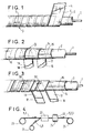
- the cable comprises a conductive core flexible 1, a flexible insulation 2 covering said core and a flexible screen 3 surrounding said insulation.
- This flexible screen 3 is constituted by a metal strip 4, which is provided with a metal coating 5 on at least its outer face, is helically wrapped around the insulation, having its windings overlapping widely, and is closed tightly on itself by said coating welding said coils to each other in any their area of overlap.
- the overlap noted 6 of the windings is illustrated by 50%. In it can be less, however, being at least 20 to 25% and preferably of the order of 40%. It defines the area of overlap welded, without the addition of external material, which is helical and along the cable for a perfect seal and conservation of performance of the screen 3 thus formed.
- the conductive core 1 is a massive core single conductor or stranded stranded core, for example bare copper, tinned, silver or copper alloy or steel covered with copper.
- the insulation is a conventional or expanded dielectric, such as PTFE, FEP, PFA, PE or PP.
- the screen 4 is preferably made by a ribbon tinned copper, whose tin coating is melted for soldering direct from its coils to each other throughout their entire area of overlap.
- the ribbon 4 can be tinned on both sides.
- This cable is advantageously a coaxial cable diameter on the insulation 2 between 0.2 and 8 mm.
- the ribbon used 4 has a width of 0.2 to 15 mm and has a winding pitch of 0.12 to 10 mm, depending on the diameter of the insulation.
- the cable can of course be provided with an outer sheath of protection, which is optional and not shown.
- the ribbon 14 is advantageously constituted by a laminated ribbon plastic / metal whose plastic side is against insulation 2.
- Ribbons 16 and 18 are advantageously constituted by metal ribbons, for example made of copper, and provided with metal coating layers 17 and 19, by example tin or tin-based or, at least on their inner side.
- the ribbons 16 and 18 are wound in the same direction and at the same not, being shifted relative to each other on the order of 1 ⁇ 4 to 3 ⁇ 4 of the value of the winding pitch. They are welded to each other and to the ribbon 14 by the covers 17 and 19.
- each of the two helical ribbons 16 and 18 has its windings overlapping widely.
- the inner longitudinal ribbon 14 is optional.
- each of the helical ribbons 16 and 18 presents a 16 'and 18' between its windings, this gap being continuous along the cable.
- the coils of the outermost helical ribbon 18 overlap totally the splice 16 'of the ribbon 16 and partially the windings of this one.
- the longitudinal tape 14 is optional in the cable screen.
- the cable of FIG. 2 or 3 may also comprise a sheath external protection, not shown. Its dimensions and not winding of its helical ribbons are as defined for the cable of Figure 1.
- the cable may comprise a longitudinal ribbon (such as ribbon 14 in Figure 2 or 3) under the ribbon helical 4, the latter then being provided with an inner metal coating and optionally the outer metal coating 5.
- insulated conductor denoted by references 1 and 2 is taken from a coil 20 and passes through a tape station 22, which receives the tape 4 5.
- This tape is taken from a roll 21 and is helically wrapped around the isolated core, as described next to Figure 1.
- the cable provided with this ribbon then passes to a station 23 of welding of the ribbon windings to each other, in which the welding is carried out, without external contribution of welding material, directly by the coating 5.
- This welding station comprises at this effect an induction coil 24 fed at high frequency, which ensures the melting of the coating 5 and the resultant welding of the coils each to others.
- the cable provided with its screen 3 thus sealed is stored on a receiving coil 25.
Landscapes
- Communication Cables (AREA)
- Insulated Conductors (AREA)
- Manufacturing Of Electric Cables (AREA)
Claims (9)
- Flexibles Koaxialkabel, das eine leitende flexible Seele (1), um die besagte Seele eine flexible Isolation (2) und um die besagte Isolation einen metallischen Schirm (2, 13, 13') aufweist, wobei der besagte Schirm einen ersten metallischen wenigstens auf seiner einen Fläche mit einem metallischen Überzug (5, 7) versehenen und schraubenförmig um die besagte Isolation umwickelten Band (4, 16) aufweist, welcher einander folgende sich entlang des besagten Kabels nach einer schraubenförmigen ununterbrochenen Überlappungszone überlappende Wicklungen aufweist, dadurch gekennzeichnet, dass der besagte erste Band (4) in der ganzen besagten Überlappungszone der besagten Wicklungen von dem besagten Überzug (5), welcher die besagten Wicklungen aneinander schweißt, an sich selbst dicht verschlossen ist.
- Flexibles Koaxialkabel nach Anspruch 1, dadurch gekennzeichnet, dass es einen zweiten schraubenförmig über den besagten ersten Band (6) umwickelten metallischen Band (18) aufweist, wobei dieser einander überlappende wenigstens auf derjenigen seiner Flächen, die auf den ersten Band zeigt, mit einem metallischen Überzug versehene Wicklungen aufweist, und wobei seine Wicklungen miteinander und mit denjenigen des besagten ersten Bandes verschweißt sind.
- Flexibles Koaxialkabel, das eine leitende flexible Seele (1), um die besagte Seele eine flexible Isolation (2) und um die besagte Isolation einen metallischen Schirm (13') aufweist, wobei der besagte Schirm einen ersten metallischen Band (16) und einen zweiten äußeren metallischen Band (18) aufweist, welche schraubenförmig um die besagte Isolation umwickelt sind und wenigstens für einen unter ihnen mit einem metallischen Überzug (17, 19) auf wenigstens einer ihrer Flächen versehen sind, dadurch gekennzeichnet, dass jeder der besagten Bänder (16, 18) entlang des besagten Kabels Wicklungen mit kontinuierlicher schraubenförmiger Fügungslücke (16', 18') aufweist, dass die Wicklungen des besagten zweiten Bandes (18) komplett die Fügungslücke des ersten Bandes (16) bedecken, und dass die Bedeckungszonen der Wicklungen der besagten Bänder von dem besagten Überzug (17, 9), welcher auf mindestens einer der beiden zueinander zeigenden Flächen der jeweiligen Bänder vorgesehen ist, dicht verschweißt sind.
- Kabel nach einem der Ansprüche 1 bis 3, dadurch gekennzeichnet, dass der besagte Schirm außerdem einen inneren metallischen längs um die besagte Isolation angebrachten Band (14) aufweist, dessen Ränder (15) sich überlappen.
- Kabel nach dem Anspruch 4, dadurch gekennzeichnet, dass der besagte innere Band (14) aus einem Kunststoff/Metallaminat besteht.
- Kabel nach einem der Ansprüche 1 und 3, dadurch gekennzeichnet, dass der besagte erste Band (4, 16) eine Steigung der Wicklung von 0,2 bis 10 mm und dass das besagte Kabel auf der besagten Isolation einen Durchmesser von 0,2 bis 8 mm aufweist.
- Kabel nach einem der Ansprüche 1 bis 6, dadurch gekennzeichnet, dass jeder mit dem Metallüberzug versehene Band aus verzinntem Kupfer besteht.
- Verfahren für die Herstellung eines Kabels nach einem der Ansprüche 1 bis 7, dadurch gekennzeichnet, dass es darin besteht, zur Schweißung der Wicklungen jedes Bandes, das den besagten Schirm bildet, das mit dem Schirm versehene Kabel ohne Zugabe von Schweißzusatzstoff einer Umfangsbeheizung zu unterziehen.
- Verfahren nach dem Anspruch 8, dadurch gekennzeichnet, dass es darin besteht, die besagte Umfangsbeheizung mittels einer hochfrequentig gespeisten Induktionswicklung (24) zu gewährleisten, welche auf einer endlosen Ausführungslinie des besagten Schirms auf das Kabel vorgesehen ist und vom besagten Kabel durchlaufen wird.
Applications Claiming Priority (2)
| Application Number | Priority Date | Filing Date | Title |
|---|---|---|---|
| FR0006689A FR2809528B1 (fr) | 2000-05-25 | 2000-05-25 | Cable coaxial flexible et procede de fabrication de celui-ci |
| FR0006689 | 2000-05-25 |
Publications (2)
| Publication Number | Publication Date |
|---|---|
| EP1158542A1 EP1158542A1 (de) | 2001-11-28 |
| EP1158542B1 true EP1158542B1 (de) | 2005-08-10 |
Family
ID=8850604
Family Applications (1)
| Application Number | Title | Priority Date | Filing Date |
|---|---|---|---|
| EP01401370A Expired - Lifetime EP1158542B1 (de) | 2000-05-25 | 2001-05-23 | Biegsames Koaxialkabel und sein Herstellungsverfahren |
Country Status (5)
| Country | Link |
|---|---|
| US (1) | US6583361B2 (de) |
| EP (1) | EP1158542B1 (de) |
| AT (1) | ATE301867T1 (de) |
| DE (1) | DE60112509T2 (de) |
| FR (1) | FR2809528B1 (de) |
Families Citing this family (31)
| Publication number | Priority date | Publication date | Assignee | Title |
|---|---|---|---|---|
| US6477767B1 (en) * | 1999-12-06 | 2002-11-12 | Hon Hai Precision Ind. Co., Ltd. | Method for removing a braiding layer of a coaxial cable |
| JP3678179B2 (ja) * | 2001-07-25 | 2005-08-03 | 日立電線株式会社 | 2重横巻2心平行極細同軸ケーブル |
| DE10303809A1 (de) * | 2003-01-31 | 2004-08-12 | Nexans | Datenübertragungskabel zum Anschluss an orstveränderliche Geräte |
| US7844344B2 (en) | 2004-03-30 | 2010-11-30 | Medtronic, Inc. | MRI-safe implantable lead |
| CA2645193C (en) * | 2006-03-09 | 2012-08-28 | Billy J. Steward | Coiled wire armored cable |
| US20070210479A1 (en) * | 2006-03-13 | 2007-09-13 | Mcintyre Leo P | Cable manufacturing method |
| GB0618108D0 (en) * | 2006-09-14 | 2006-10-25 | Technip France Sa | Subsea umbilical |
| US9044593B2 (en) | 2007-02-14 | 2015-06-02 | Medtronic, Inc. | Discontinuous conductive filler polymer-matrix composites for electromagnetic shielding |
| US8483842B2 (en) | 2007-04-25 | 2013-07-09 | Medtronic, Inc. | Lead or lead extension having a conductive body and conductive body contact |
| US9037263B2 (en) | 2008-03-12 | 2015-05-19 | Medtronic, Inc. | System and method for implantable medical device lead shielding |
| DE102009009558B4 (de) * | 2009-02-19 | 2013-08-29 | Heraeus Precious Metals Gmbh & Co. Kg | Gewickeltes Band als elektrischer Leiter für Stimulationselektroden |
| JP5394507B2 (ja) * | 2009-03-06 | 2014-01-22 | サン−ゴバン パフォーマンス プラスティックス コーポレイション | 重ね合わせ型導電性ヘリカルスプリング |
| EP2429633B1 (de) | 2009-04-30 | 2014-12-17 | Medtronic, Inc. | Erdung einer abschirmung einer implantierbaren medizinischen elektrode |
| US9728304B2 (en) * | 2009-07-16 | 2017-08-08 | Pct International, Inc. | Shielding tape with multiple foil layers |
| MX2012003346A (es) * | 2009-10-02 | 2012-04-20 | Saint Gobain Performance Plast | Sello modular de polimero de interferencia electromagnetica/interf erencia de radiofrecuencia (emi/rfi). |
| US8471149B2 (en) * | 2010-03-04 | 2013-06-25 | Technical Services For Electronics, Inc. | Shielded electrical cable and method of making the same |
| JP5699872B2 (ja) * | 2011-01-24 | 2015-04-15 | 日立金属株式会社 | 差動信号伝送用ケーブル |
| US9404249B2 (en) * | 2012-01-18 | 2016-08-02 | Adc Acquisition Company | Ultra light fiber placed truss |
| US9463317B2 (en) | 2012-04-19 | 2016-10-11 | Medtronic, Inc. | Paired medical lead bodies with braided conductive shields having different physical parameter values |
| JP5825219B2 (ja) * | 2012-07-31 | 2015-12-02 | 日立金属株式会社 | 差動信号伝送用ケーブル、多芯差動信号伝送用ケーブル、及び差動信号伝送用ケーブルの製造方法ならびに製造装置 |
| US9993638B2 (en) | 2013-12-14 | 2018-06-12 | Medtronic, Inc. | Devices, systems and methods to reduce coupling of a shield and a conductor within an implantable medical lead |
| EP3134905B1 (de) * | 2014-04-25 | 2020-03-18 | LEONI Kabel GmbH | Datenkabel |
| WO2016014427A1 (en) | 2014-07-23 | 2016-01-28 | Medtronic, Inc. | Methods of shielding implantable medical leads and implantable medical lead extensions |
| US10155111B2 (en) | 2014-07-24 | 2018-12-18 | Medtronic, Inc. | Methods of shielding implantable medical leads and implantable medical lead extensions |
| US9691524B2 (en) * | 2014-12-08 | 2017-06-27 | Nkt Hv Cables Gmbh | Systems and methods for applying metallic laminates to cables |
| JP2016201273A (ja) * | 2015-04-10 | 2016-12-01 | 日立金属株式会社 | 差動信号伝送ケーブル及び多芯差動信号伝送ケーブル |
| US11848120B2 (en) | 2020-06-05 | 2023-12-19 | Pct International, Inc. | Quad-shield cable |
| EP3971915A1 (de) | 2020-09-18 | 2022-03-23 | Nexans | Mehrschichtige radiale wassersperre für schnelle herstellung |
| EP4016552B1 (de) * | 2020-12-15 | 2026-03-18 | Nexans | Bleifreie wassersperre |
| CN112803170A (zh) * | 2021-03-17 | 2021-05-14 | 江苏亨鑫科技有限公司 | 一种应急用漏泄同轴电缆 |
| CN115939720B (zh) * | 2023-01-31 | 2023-07-11 | 滁州润翰微波科技有限公司 | 一种柔性定向泄漏同轴电缆的生产工艺及生产设备 |
Family Cites Families (9)
| Publication number | Priority date | Publication date | Assignee | Title |
|---|---|---|---|---|
| US3636234A (en) * | 1969-12-04 | 1972-01-18 | United States Steel Corp | Communication cable |
| US3644662A (en) * | 1971-01-11 | 1972-02-22 | Gen Electric | Stress cascade-graded cable termination |
| USRE30228E (en) * | 1973-02-23 | 1980-03-11 | General Cable Corporation | Power cable with corrugated or smooth longitudinally folded metallic shielding tape |
| US4340771A (en) * | 1981-03-16 | 1982-07-20 | Siecor Corporation | Communications cable having combination shielding-armor member |
| US4694122A (en) * | 1986-03-04 | 1987-09-15 | Cooper Industries, Inc. | Flexible cable with multiple layer metallic shield |
| US4894488A (en) * | 1988-03-21 | 1990-01-16 | Comm/Scope, Inc. | High frequency signal cable with improved electrical dissipation factor and method of producing same |
| US5293001A (en) * | 1992-04-14 | 1994-03-08 | Belden Wire & Cable Company | Flexible shielded cable |
| US5442131A (en) * | 1993-07-23 | 1995-08-15 | Borgwarth; Dennis | High energy coaxial cable cooling apparatus |
| US5574260B1 (en) * | 1995-03-06 | 2000-01-18 | Gore & Ass | Composite conductor having improved high frequency signal transmission characteristics |
-
2000
- 2000-05-25 FR FR0006689A patent/FR2809528B1/fr not_active Expired - Fee Related
-
2001
- 2001-05-23 AT AT01401370T patent/ATE301867T1/de not_active IP Right Cessation
- 2001-05-23 DE DE60112509T patent/DE60112509T2/de not_active Expired - Fee Related
- 2001-05-23 EP EP01401370A patent/EP1158542B1/de not_active Expired - Lifetime
- 2001-05-24 US US09/863,310 patent/US6583361B2/en not_active Expired - Fee Related
Also Published As
| Publication number | Publication date |
|---|---|
| ATE301867T1 (de) | 2005-08-15 |
| FR2809528B1 (fr) | 2002-07-19 |
| DE60112509D1 (de) | 2005-09-15 |
| US20020003046A1 (en) | 2002-01-10 |
| US6583361B2 (en) | 2003-06-24 |
| FR2809528A1 (fr) | 2001-11-30 |
| DE60112509T2 (de) | 2006-06-01 |
| EP1158542A1 (de) | 2001-11-28 |
Similar Documents
| Publication | Publication Date | Title |
|---|---|---|
| EP1158542A1 (de) | Biegsames Koaxialkabel und sein Herstellungsverfahren | |
| EP2146395B1 (de) | Anschlussmuffe eines Supraleiterkabels und Abschluss des Anschlusses mit Hilfe dieser Muffe | |
| EP1145842B1 (de) | Verbundglasscheibe | |
| FR2485859A1 (fr) | Cable flexible de chauffage electrique a auto-limitation de temperature | |
| FR2654977A1 (fr) | Procede et piece de raccordement utilisant une resistance electrique pour le soudage d'elements en matiere plastique. | |
| EP0554160B1 (de) | Elektrisches Hochfrequenzkabel | |
| EP0430762A2 (de) | Verfahren und Vorrichtung zum Ermitteln des Erwärmungszustandes eines Teiles aus thermoplastischem Material und Verbindungsstück zum Verschweissen von Kunststoffteilen | |
| EP0326441B1 (de) | Herstellungsverfahren einer Halterung zur elektromagnetischen Abschirmung, Maschine für die Ausführung dieses Verfahrens und mit Hilfe dieses Verfahrens oder dieser Maschine hergestellte Halterung | |
| EP2110887B1 (de) | Verbindungsanordnung von zwei Supraleitungskabeln | |
| CH695403A5 (fr) | Câble de transmission de données à haute vitesse comportant plusieurs paires torsadées blindées. | |
| FR2484162A1 (fr) | Dispositif de raccordement etanche d'un cable coaxial sous-marin a un repeteur, procede de fabrication de ce dispositif et moule utilisable dans ce procede | |
| EP1816656B1 (de) | Korrosionsgeschütztes elektrisches Kabel | |
| EP0615091A1 (de) | Heissschweissbare Rohrverbindung aus Kunststoff und Herstellungsverfahren | |
| EP0122826B1 (de) | Vieldrahtiger leicht verbind und direkt lötbarer elektrischer Leiter | |
| FR2521732A1 (fr) | Cables a fibres optiques et methode pour les fabriquer | |
| EP2038978A1 (de) | Elektrische durchführungsstruktur für ein supraleitendes element | |
| CH621653A5 (de) | ||
| WO2014176706A1 (fr) | Procede de fabrication d'un cable chauffant et cable chauffant realise selon ce procede | |
| FR2627026A1 (fr) | Procede pour realiser l'etancheite entre un cable ou element analogue et une conduite externe recevant ce cable et bande composite pour la mise en oeuvre de ce procede | |
| FR3028677A1 (fr) | Assemblage d'un ensemble de raccordement electrique | |
| EP0105068B1 (de) | Elektrische Schweissmuffe aus Kunststoff und Verfahren zu deren Herstellung | |
| FR2519505A1 (fr) | Cable chauffant et son procede de fabrication | |
| EP2375504A1 (de) | Verbindungsvorrichtung von zwei Supraleitungskabeln | |
| FR2472252A1 (fr) | Cable electrique multifilaire isole, a conducteurs proteges, soudables et non thermo collants | |
| CH277798A (fr) | Tube résistant à l'humidité. |
Legal Events
| Date | Code | Title | Description |
|---|---|---|---|
| PUAI | Public reference made under article 153(3) epc to a published international application that has entered the european phase |
Free format text: ORIGINAL CODE: 0009012 |
|
| AK | Designated contracting states |
Kind code of ref document: A1 Designated state(s): AT BE CH CY DE DK ES FI FR GB GR IE IT LI LU MC NL PT SE TR |
|
| AX | Request for extension of the european patent |
Free format text: AL;LT;LV;MK;RO;SI |
|
| 17P | Request for examination filed |
Effective date: 20020528 |
|
| AKX | Designation fees paid |
Free format text: AT BE CH CY DE DK ES FI FR GB GR IE IT LI LU MC NL PT SE TR |
|
| GRAP | Despatch of communication of intention to grant a patent |
Free format text: ORIGINAL CODE: EPIDOSNIGR1 |
|
| GRAS | Grant fee paid |
Free format text: ORIGINAL CODE: EPIDOSNIGR3 |
|
| GRAA | (expected) grant |
Free format text: ORIGINAL CODE: 0009210 |
|
| AK | Designated contracting states |
Kind code of ref document: B1 Designated state(s): AT BE CH CY DE DK ES FI FR GB GR IE IT LI LU MC NL PT SE TR |
|
| PG25 | Lapsed in a contracting state [announced via postgrant information from national office to epo] |
Ref country code: NL Free format text: LAPSE BECAUSE OF FAILURE TO SUBMIT A TRANSLATION OF THE DESCRIPTION OR TO PAY THE FEE WITHIN THE PRESCRIBED TIME-LIMIT Effective date: 20050810 Ref country code: AT Free format text: LAPSE BECAUSE OF FAILURE TO SUBMIT A TRANSLATION OF THE DESCRIPTION OR TO PAY THE FEE WITHIN THE PRESCRIBED TIME-LIMIT Effective date: 20050810 Ref country code: FI Free format text: LAPSE BECAUSE OF FAILURE TO SUBMIT A TRANSLATION OF THE DESCRIPTION OR TO PAY THE FEE WITHIN THE PRESCRIBED TIME-LIMIT Effective date: 20050810 Ref country code: TR Free format text: LAPSE BECAUSE OF FAILURE TO SUBMIT A TRANSLATION OF THE DESCRIPTION OR TO PAY THE FEE WITHIN THE PRESCRIBED TIME-LIMIT Effective date: 20050810 |
|
| REG | Reference to a national code |
Ref country code: GB Ref legal event code: FG4D Free format text: NOT ENGLISH |
|
| REG | Reference to a national code |
Ref country code: CH Ref legal event code: EP |
|
| REG | Reference to a national code |
Ref country code: IE Ref legal event code: FG4D Free format text: LANGUAGE OF EP DOCUMENT: FRENCH |
|
| REF | Corresponds to: |
Ref document number: 60112509 Country of ref document: DE Date of ref document: 20050915 Kind code of ref document: P |
|
| GBT | Gb: translation of ep patent filed (gb section 77(6)(a)/1977) |
Effective date: 20050917 |
|
| PG25 | Lapsed in a contracting state [announced via postgrant information from national office to epo] |
Ref country code: GR Free format text: LAPSE BECAUSE OF FAILURE TO SUBMIT A TRANSLATION OF THE DESCRIPTION OR TO PAY THE FEE WITHIN THE PRESCRIBED TIME-LIMIT Effective date: 20051110 Ref country code: DK Free format text: LAPSE BECAUSE OF FAILURE TO SUBMIT A TRANSLATION OF THE DESCRIPTION OR TO PAY THE FEE WITHIN THE PRESCRIBED TIME-LIMIT Effective date: 20051110 Ref country code: SE Free format text: LAPSE BECAUSE OF FAILURE TO SUBMIT A TRANSLATION OF THE DESCRIPTION OR TO PAY THE FEE WITHIN THE PRESCRIBED TIME-LIMIT Effective date: 20051110 |
|
| PG25 | Lapsed in a contracting state [announced via postgrant information from national office to epo] |
Ref country code: ES Free format text: LAPSE BECAUSE OF FAILURE TO SUBMIT A TRANSLATION OF THE DESCRIPTION OR TO PAY THE FEE WITHIN THE PRESCRIBED TIME-LIMIT Effective date: 20051121 |
|
| PG25 | Lapsed in a contracting state [announced via postgrant information from national office to epo] |
Ref country code: PT Free format text: LAPSE BECAUSE OF FAILURE TO SUBMIT A TRANSLATION OF THE DESCRIPTION OR TO PAY THE FEE WITHIN THE PRESCRIBED TIME-LIMIT Effective date: 20060110 |
|
| NLV1 | Nl: lapsed or annulled due to failure to fulfill the requirements of art. 29p and 29m of the patents act | ||
| PG25 | Lapsed in a contracting state [announced via postgrant information from national office to epo] |
Ref country code: CH Free format text: LAPSE BECAUSE OF NON-PAYMENT OF DUE FEES Effective date: 20060531 Ref country code: MC Free format text: LAPSE BECAUSE OF NON-PAYMENT OF DUE FEES Effective date: 20060531 Ref country code: LI Free format text: LAPSE BECAUSE OF NON-PAYMENT OF DUE FEES Effective date: 20060531 |
|
| PLBE | No opposition filed within time limit |
Free format text: ORIGINAL CODE: 0009261 |
|
| STAA | Information on the status of an ep patent application or granted ep patent |
Free format text: STATUS: NO OPPOSITION FILED WITHIN TIME LIMIT |
|
| 26N | No opposition filed |
Effective date: 20060511 |
|
| REG | Reference to a national code |
Ref country code: CH Ref legal event code: PL |
|
| PGFP | Annual fee paid to national office [announced via postgrant information from national office to epo] |
Ref country code: DE Payment date: 20070522 Year of fee payment: 7 |
|
| PGFP | Annual fee paid to national office [announced via postgrant information from national office to epo] |
Ref country code: IE Payment date: 20070524 Year of fee payment: 7 |
|
| PGFP | Annual fee paid to national office [announced via postgrant information from national office to epo] |
Ref country code: BE Payment date: 20070531 Year of fee payment: 7 |
|
| PGFP | Annual fee paid to national office [announced via postgrant information from national office to epo] |
Ref country code: GB Payment date: 20070522 Year of fee payment: 7 |
|
| PGFP | Annual fee paid to national office [announced via postgrant information from national office to epo] |
Ref country code: IT Payment date: 20070524 Year of fee payment: 7 |
|
| PGFP | Annual fee paid to national office [announced via postgrant information from national office to epo] |
Ref country code: FR Payment date: 20070516 Year of fee payment: 7 |
|
| PG25 | Lapsed in a contracting state [announced via postgrant information from national office to epo] |
Ref country code: LU Free format text: LAPSE BECAUSE OF NON-PAYMENT OF DUE FEES Effective date: 20060523 |
|
| PG25 | Lapsed in a contracting state [announced via postgrant information from national office to epo] |
Ref country code: CY Free format text: LAPSE BECAUSE OF FAILURE TO SUBMIT A TRANSLATION OF THE DESCRIPTION OR TO PAY THE FEE WITHIN THE PRESCRIBED TIME-LIMIT Effective date: 20050810 |
|
| BERE | Be: lapsed |
Owner name: NEXANS Effective date: 20080531 |
|
| GBPC | Gb: european patent ceased through non-payment of renewal fee |
Effective date: 20080523 |
|
| REG | Reference to a national code |
Ref country code: IE Ref legal event code: MM4A |
|
| REG | Reference to a national code |
Ref country code: FR Ref legal event code: ST Effective date: 20090119 |
|
| PG25 | Lapsed in a contracting state [announced via postgrant information from national office to epo] |
Ref country code: BE Free format text: LAPSE BECAUSE OF NON-PAYMENT OF DUE FEES Effective date: 20080531 |
|
| PG25 | Lapsed in a contracting state [announced via postgrant information from national office to epo] |
Ref country code: DE Free format text: LAPSE BECAUSE OF NON-PAYMENT OF DUE FEES Effective date: 20081202 Ref country code: IE Free format text: LAPSE BECAUSE OF NON-PAYMENT OF DUE FEES Effective date: 20080523 Ref country code: FR Free format text: LAPSE BECAUSE OF NON-PAYMENT OF DUE FEES Effective date: 20080602 |
|
| PG25 | Lapsed in a contracting state [announced via postgrant information from national office to epo] |
Ref country code: GB Free format text: LAPSE BECAUSE OF NON-PAYMENT OF DUE FEES Effective date: 20080523 |
|
| PG25 | Lapsed in a contracting state [announced via postgrant information from national office to epo] |
Ref country code: IT Free format text: LAPSE BECAUSE OF NON-PAYMENT OF DUE FEES Effective date: 20080523 |