EP0105381A1 - Coupe-circuit - Google Patents
Coupe-circuit Download PDFInfo
- Publication number
- EP0105381A1 EP0105381A1 EP83901098A EP83901098A EP0105381A1 EP 0105381 A1 EP0105381 A1 EP 0105381A1 EP 83901098 A EP83901098 A EP 83901098A EP 83901098 A EP83901098 A EP 83901098A EP 0105381 A1 EP0105381 A1 EP 0105381A1
- Authority
- EP
- European Patent Office
- Prior art keywords
- contact
- arc
- contactor
- movable
- circuit breaker
- Prior art date
- Legal status (The legal status is an assumption and is not a legal conclusion. Google has not performed a legal analysis and makes no representation as to the accuracy of the status listed.)
- Granted
Links
- 238000007599 discharging Methods 0.000 claims description 4
- 238000000926 separation method Methods 0.000 claims description 3
- 230000000063 preceeding effect Effects 0.000 claims 2
- 238000009432 framing Methods 0.000 description 10
- 230000000670 limiting effect Effects 0.000 description 6
- 230000001629 suppression Effects 0.000 description 5
- WABPQHHGFIMREM-UHFFFAOYSA-N lead(0) Chemical compound [Pb] WABPQHHGFIMREM-UHFFFAOYSA-N 0.000 description 4
- 239000002184 metal Substances 0.000 description 4
- 239000004065 semiconductor Substances 0.000 description 3
- 239000012530 fluid Substances 0.000 description 2
- 239000004020 conductor Substances 0.000 description 1
- 239000000470 constituent Substances 0.000 description 1
- 238000001816 cooling Methods 0.000 description 1
- 230000000694 effects Effects 0.000 description 1
- 239000000696 magnetic material Substances 0.000 description 1
- 239000000463 material Substances 0.000 description 1
- 238000009877 rendering Methods 0.000 description 1
- 230000000717 retained effect Effects 0.000 description 1
- 230000000979 retarding effect Effects 0.000 description 1
Images


Classifications
-
- H—ELECTRICITY
- H01—ELECTRIC ELEMENTS
- H01H—ELECTRIC SWITCHES; RELAYS; SELECTORS; EMERGENCY PROTECTIVE DEVICES
- H01H73/00—Protective overload circuit-breaking switches in which excess current opens the contacts by automatic release of mechanical energy stored by previous operation of a hand reset mechanism
- H01H73/02—Details
- H01H73/18—Means for extinguishing or suppressing arc
Definitions
- This invention relates to circuit breakers capable of breaking associated circuit upon a short-circuit or when an overcurrent higher than a rated current keeps flowing and, more specifically, to a circuit breaker improved remarkably in the current limiting effect so as to be able to reliably protect any circuit specifically including such elements not withstandable to short-circuit current as semiconductors.
- the circuit breaker of the kind referred to comprises, as has been disclosed in, for example, U. S. Patent No. 3,329,913 and Japanese Patent Publication No. 18258/1966, a fixed contactor carrying a fixed contact, a movable contactor carrying a movable contact contactable with the fixed contact; a manual contact opening and closing mechanism normally operable to separate the movalbe contactor from the fixed contactor and including a trip means which forcibly separates the movable contactor from the fixed contactor, an electromagnetic device operating in response to the short-circuit current as well as the overcurrent to attract an armature linked to the trip means, and an arc suppressing means disposed adjacent contacting and separating position of the fixed and movable contacts.
- the contacts are normally closed and opened by means of the manual contact opening and closing mechanism which moves the movable contactor with respect to the fixed contactor whereas, upon the short-circuit or when the overcurrent higher than the rated current keeps flowing, they are opened by means of the trip means which separates the movable con.tactor from the fixed contactor with an actuation of the electromagnetic device and attraction of the armature. An arc generated upon such contact opening is shifted towards the arc suppressing means to be therein divided, cooled and suppressed.
- a primary object of the present invention is to obtain a circuit breaker which shortens the required time from the separating motion of the movable contactor from the fixed contactor upon the actuation of the electromagnetic device detected a current higher than a predetermined rated value to the arc suppression to a large extent, and improves the current limiting effect remarkably.
- the movable contactor is so formed that at least a part holding the movable contact will pass through the interior of the arc suppressing means upon the trip operation and contact opening motion, whereby the arc suppressing efficiency is remarkably elevated and thus the current limiting effect can be improved.
- the movable contactor is caused to be propelled so as to promote its opening motion immediately after a release from a latch member upon the trip operation, whereby the instantaneous responsibility is made excellent and thus the current limiting effect is elevated.
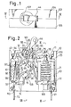
- FIG. I is a plan view of the circuit breaker according to the present invention
- FIG. 2 is a side elevation of the breaker of FIG. 1 with one of two dividable halves of its casing removed
- FIG. 3 is a perspective view as disassembled into componential parts of the circuit breaker with the casing removed
- FIG. 4 is a sectioned view as taken along line IV-IV in FIG. 1
- FIG. 5 is a sectioned view showing main parts only of FIG. 4 in contact closing state
- FIG. 6 is a sectioned view similar to FIG. 5 in a state where the electromagnetic device of the foregoing circuit breaker is completely actuated due to the overcurrent
- FIG. 7 is an endwise elevation of the foregoing circuit breaker
- FIG. 8 is a sectioned view taken along line VIII-VIII in FIG. 2
- FIG. 9 is a sectioned view taken along line IX-IX in FIG. 2.
- a circuit breaker 10 is provided with an electromagnetic device 11, a manual contact opening and closing mechanism 12 including a trip mechanism operably coupled to the electromagnetic device 11 and being shiftable into a tripped state when a large current is caused to flow, a closing and opening contact section 13 including a movable contactor 14 and fixed contactor 15 and provided to be capable of contacting a movable contact 16 of the movable contactor 14 with and separating the same from a fixed contact 17 of the fixed contactor by operating the manual contact opening and closing mechanism 12, and an arc suppressing means 18 provided for allowing at least a part of the movable contactor 14 where the movable contact 16 is held or secured to pass therethrough when the movable contactor 14 performs its contact opening motion.
- a rectangular yoke 20 of a magnetic material is provided, and a cylinder 22 on which a coil 21 for detecting the overcurrent is wound is secured to the yoke 20.
- a magnetic head 23 is secured substantially in the center, and first plunger 24 to which loads of a viscous fluid and spring are applied and second plunger 25 are disposed to oppose each other with the magnetic head 23 interposed between them.
- any overcurrent flowed through the coil 21 causes initially the first plunger 24 to be attracted to the magnetic head 23 while being subjected to a retarding action due to the viscousity of the fluid and spring load and then the second plunger 25 also attracted to the head 23 with an increased magnetic force.
- the second plunger 25 is caused to immediately be attracted to the magnetic head 23 without waiting for the attraction of the first plunger 24 to the head 23.
- a frame 28 for supporting the manual contact opening and closing mechanism including the trip mechanism so as to be integral and to project substantially in extended direction of the upper beam part of the yoke 20.
- the frame 28 comprises vertically and mutually parallelly extended short and long framing parts 29 and 30.
- shaft bearing holes 32 and 33 respectively made in the foremost end extension 31 and rearward upper corner, as well as a further shaft bearing hole 34 made in the rearward portion below the hole 33.
- the long framing part 30 is provided, on the other hand, with a shaft bearing hole 36 made in an expanded part 35 provided at a position corresponding to the extension 31 of the short framing part 29, and with shaft bearing holes 37 and 38 respectively in the rearward portion at its corresponding positions to the holes 33 and 34 in the short framing part 29.
- a reverse L-shaped sliding aperture 39 is formed to have at a part an arcuate edge 40, while the tip end part is bent substantially perpendicularly.
- Such bent part 41 is provided at the upper edge with an engaging part 42 and at the lower edge with a horizontal arc running extension 43 of a small disk shape.
- a handle 44 has a shaft bearing hole 46 made in the center of a lower cylindrical part 45 which is provided at a part of its periphery with an expanded part 48 having a through hole 47.
- the handle 44 is rotatably supported by the frame 28 with a supporting shaft 49 passed through the hole 46 and born at the shaft bearing holes 32 and 36 of the short and long framing parts 29 and 30.
- a supporting shaft 49 passed through the hole 46 and born at the shaft bearing holes 32 and 36 of the short and long framing parts 29 and 30.
- one leg 51 of a U-shaped link pin 50 is inserted, and the free end of this leg 51 is freely engaged in the L-shaped sliding aperture 3.9 of the long framing part 30 to be shiftable along the arcuate edge 40.
- the other leg 52 of the link pin 50 is passed through respective shaft bearing holes 57 and 58 of projections 55 and 56 provided to oppose each other on a link arm 54 while its free end is engaged freely in the sliding aperture 39 so as to be slidable in the other vertical part thereof.
- the link arm 54 itself is provided with a base part 59 of a reverse U-shape as seen endwise, and an engaging opening 60 is made in the base part 59.
- an engaging opening 60 is made in the base part 59.
- two of the arms has a kicking tongue 56 projected from the lower edge as bent into an L-shape and slightly slanted upward with respect to the vertical direction, and also a stopping projection 66 projected from the upper edge as bent also into an L-shape to be substantially horizontal.
- a support shaft 67 is born in the shaft bearing holes 63 and 64 at the tip ends of the arms 61 and 62, as passed through a shaft bearing hole 68 of the movable contactor 14 of an angled shape and connected through the lead wire 26 to one end of the detecting coil 21, whereby the movable contactor 14 is pivoted to the link arm 54.
- an expanded part 70 having an engaging hole 69 is provided to project upward, while the movable contact 16 made of a contacting material preferably of a high conductivity is secured to the tip end at its lower edge.
- the above described movable contact 16 of the movable contactor 14 is disposed to be contactable with the fixed contact 17 made preferably of a highly conductive material and secured to the fixed contactor 15 disposed below the movable contactor 14.
- the fixed contactor 15 per se is made to be slanted at one leg part of a U-shaped portion 71 to which the fixed contact 17 is secured, to be downward toward the arc suppressing means 18 so as to provide an arc running part 72 extending further downward to a position opposing the arc running extension 43 of the frame 28, while a connecting part 74 made integral with a terminal metal fitting 73 is provided as extended from the other leg part of the U-shaped portion 71 and bent into an L-shape.
- an interlocking arm 76 of the trip mechanism is pivoted to a support shaft 75 born in the shaft bearing holes 33 and 37 of the frame 28.
- This interlocking arm includes a base part 78 having a notch 77 for engaging thereto the head part of the second plunger 25 of the electromagnetic device 11, a pair of arms 79 and 80 are extended from the forward end of the base part 78 vertically and mutually parallelly, the support shaft 75 is born in shaft bearing holes 81 and 82 made in the respective arms 79 and 80, and the interlocking arm 76 is pivoted to the frame 28 as referred to above.
- the one arm 79 is extended downward as bent to be L-shape, and a kicking foot 83 is projected to be capable of hitting the kicking tongue 65 of the link arm 54 to propel the same.
- a latch member 84 of an L-shape as seen sideward and operating integrally with the interlocking arm 76 is pivoted through shaft bearing holes 85 and 86, one extension of this latch member 84 is formed to be an arm 87 which is normally separated slightly from the lower surface of the base part 78 of the interlocking arm 76 but is engageable thereto upon its actuation, and the other extension is extended downward to be provided as a leg 89 having a hook 88 to be projected into the engaging opening 60 of the link arm 54 and engaged to an edge of the same.
- a coil spring 90 is mounted about the support shaft 49 of the above described handle 44, and this spring 90 provides always to the handle 44 a rotating force acting in the direction of the contact opening motion, that is, in the clockwise direction in FIG. 2, as being engaged at one end to an angled corner edge of the sliding aperture 39 and at the other end to the leg 51 of the link pin 50 while being guided by a semi-annular guide 53 on the lower part 45 of the handle 44.
- a return spring 91 is engaged while the other end thereof is engaged in the engaging hole 69 of the movable contactor 14, so that the cotactor 14 will be receiving always a force acting in the direction of separating from the fixed contactor 15.
- an interlocking-arm spring 92 and latch spring 93 are mounted about the support shaft 75 of the interlocking arm 76, and the interlocking-arm spring 92 is engaged at one end to the lower surface of the base part 78 of the interlocking arm 76 and at the other end to an engaging shaft 94 held in the shaft bearing holes 34 and 38 of the frame 28 so as to always urge the interlocking arm 76 in the counterclockwise direction in FIG.
- the latch spring 93 is engaged at one end to the engaging shaft 94 and at the other end to such a proper portion of the frame 28 as, for example, circumferential edge of a round hole 95 made in the long framing part 30 so as to be effective to urge the latch member 84 always in the counterclockwise direction, that is, to be engageable to the link arm 54.
- This arc suppressing means 18 is provided with a recess 96 through which the tip end of the movable contactor 14 is allowed to pass, and comprises a plurality of deion grids 97 of a U-shape as seen flatly and mutually separated with a small clearance. These deion grids 97 are held between both side plates 98 and 99 and provided at their end edges with an end plate 100 fixed to the side plates 98 and 99. Arc gas discharging opening 101 is made in the end plate 100 while, in the center of the opening 101, a direct-discharge restricting plate part 102 is provided to oppose the recess 96 of the deion grids 97.
- a casing 103 for housing therein all of the foregoing constituent members is provided for defining a housing space with mutual -engagement of two divided casing halves 104 and 105, which are respectively provided with a-notch for forming a rectangular slit 106 in an.end wall on the side where the arc suppressing means 18 is disposed when engaged to each other.
- the slit 106 is positioned behind the direct-discharge restricting plate part 102.
- the casing 103 further defines in its upper surface part a handle hole 107 which is provided for projecting the handle 44 thereout and restricting its rotation within a predetermined angle of rotation, while allowing the lower part 45 of the handle 44 to be rotatably seated immediately below the hole 107.
- a projection suitable for restricting rotating stroke of the link arm 54 as being engaged to the stopping projection 66 of the arm 54 is provided, and a square-shaped pillar 108 to which the U-shaped part 71 of the fixed contactor 15 can be fitted and, preferably, a projected wall for insulating the contactor from environment of the lead wire 26 on the side opposite to the pillar are provided.
- bed parts 109 and 110 are provided to project for compactly and stably seating thereon the electromagnetic device 11 and arc suppressing means 18.
- Such elastic member as a spring may be attached to the above restricting projection so asto cause the link arm 54 to be repelled back, whereby it is made possible to promote rotary motion of the link arm 54 when it rotates in the counterclockwise direction after a rapid rotation in the clockwise direction.
- any upward motion more than required of the link arm 54 is restricted by the projection in the casing.
- the handle 44 is rotated from the position of FIG. 2 or 4 to that of FIG. 5, resisting thus against the biasing forces of the coil spring 90 mounted on the support shaft 49 for the handle and of the return spring 91, the handle 44 is stopped at its position rotated counterclockwise overcoming the biasing forces of the springs 90 and 91 when the position of the one leg 51 of the link pin 50 inserted in the through hole 47 of the expanded part 48 at the lower part 45 of the handle has exceeded a line connecting between the handle support shaft 49 and the other leg 52 of the link pin 50, and the handle is retained there.
- the link pin 50 is made to be substantially in vertical state in which the hook 88 of the latch member 84 being engaged edgewise to the engaging opening 60 of the link arm 54, the link arm 54 as well as the movable contactor 14 coupled through the support shaft 67 to the arm 54 are both rotated to be slanted forward to have the movable contact 16 contacted with the fixed contact, and the contact closing state is reached.
- an electric circuit is formed by means of the terminal metal fitting 27, coil 21, lead wire 26, movable contactor 14, movable contact 16, fixed contact 17, fixed contactor 15 and terminal metal fitting 73.
- the interlocking arm 76 and latch member 84 are rotated with the support shaft 75 as the center, the hook 88 of the latch member 84 is disengaged from the edge of the engaging aperture 60 of the link arm 54 and, as shown in FIG. 6, the kicking tongue 65 of the link arm 54 is hit by the kicking foot 83 of the interlocking arm 76 to be moved upward.
- the link arm 54 is, therefore, subjected to a sort of firm starting force due to such hitting and propelling motion performing a unique action in the present invention, the rotary force of the link arm 54 is rapidly elevated, and the movable contactor 14 is rapidly separated from the fixed contactor 15 to reach the position of FIG. 6 with a cooperation of tension force of the return spring 91 engaged to the movable contactor 14 coupled to the link arm 54.
- the electromagnetic driving force produced by the current flowing through the fixed and movable contactors 15 and 14 is caused to act on the arc generated upon the contact opening as has been well known and, in addition, the movable contact 16 itself of the movable contactor 14 positioned outside the arc suppressing means during the contact closing state is caused to pass immediately through the recess 96 of the arc suppressing means 18, the arc is divided, cooled and extremely effectively suppressed within this arc suppressing means.
- the generaged arc is made to effectively shift to the arc suppressing means 18 even before it reaches the arc running part 72 so that the arc suppressing efficiency will be also elevated by this arrangement.
- the movable contactor 14 has moved upward, further, the upper part of its tip end is positioned very close to the frame 28 so that there can be formed an electric path through the frame 28 having the arc running extension 43 and the yoke 20 integral with the frame 28 after the contact opening.
- the provision of the direct discharge restricting plate 102 in the discharge opening 101 as aligned in the longitudinal direction of the casing 103 with the slit 106 causes the arc gas to go around the restricting plate 102 without being directly discharged to the exterior, whereby the gas discharge can be made relatively gradual and any rapid arc gas discharge can be prevented.
- the rapid arc gas discharge is not desirable since the divided arcs inside the arc suppressing means 18 are caused to be mutually short-circuited through the arc gas in the exterior of the suppressing means again and the arc suppressing efficiency is deteriorated.
- the slight separation at one arm of the latch member 84 from the lower surface at the base portion of the interlocking arm 76 renders the second plunger 25 of the electromagnetic device 11 not to be subjected to any load incurred by the weight of the latch member 84 as well as its associated members but rather to be actuatable at a predetermined current level upon, for example, the short-circuit.
- the short-circuit current that is, a current which is two or three times as large as the rated current flows
- the second plunger 25 is immediately attracted to the magnetic head 23 since the exciting force of the coil 21 is extremely large, and the interlocking arm 7 6 and latch member 84 are caused to be instantaneously actuated.
- the same operation as that performed when the overcurrent flows as has been disclosed is also performed upon the short-circuit, and the same function can be obtained.
- the movable-contact carrying part of the movable contactor is always caused to pass through the interior of the arc suppressing means upon the opening operation of the.closing and opening contact section, and.the arc dividing, cooling and suppressing are remarkably improved.
- the link arm 54 supporting the movable contactor is hit and propelled, whereby the contact opening operation with respect to the fixed contactor can be performed extremely quickly.
- the current limiting effect of the breaker can be improved to a large extent and the large current flow to the circuit can be effectively prevented, so that such element weak to the overcurrent as semiconductors even included in the circuit can be sufficiently protected and remarkable effects can be realized when utilized in the technical field as referred to.
Landscapes
- Breakers (AREA)
Abstract
Applications Claiming Priority (2)
| Application Number | Priority Date | Filing Date | Title |
|---|---|---|---|
| JP50914/82 | 1982-03-31 | ||
| JP57050914A JPS58169732A (ja) | 1982-03-31 | 1982-03-31 | 回路遮断器 |
Publications (3)
| Publication Number | Publication Date |
|---|---|
| EP0105381A1 true EP0105381A1 (fr) | 1984-04-18 |
| EP0105381A4 EP0105381A4 (fr) | 1986-05-14 |
| EP0105381B1 EP0105381B1 (fr) | 1991-09-25 |
Family
ID=12872042
Family Applications (1)
| Application Number | Title | Priority Date | Filing Date |
|---|---|---|---|
| EP83901098A Expired - Lifetime EP0105381B1 (fr) | 1982-03-31 | 1983-03-31 | Coupe-circuit |
Country Status (6)
| Country | Link |
|---|---|
| US (1) | US4514709A (fr) |
| EP (1) | EP0105381B1 (fr) |
| JP (1) | JPS58169732A (fr) |
| DE (1) | DE3323474C2 (fr) |
| GB (1) | GB2127225B (fr) |
| WO (1) | WO1983003496A1 (fr) |
Cited By (1)
| Publication number | Priority date | Publication date | Assignee | Title |
|---|---|---|---|---|
| EP0887832A3 (fr) * | 1997-05-28 | 2000-03-08 | Eaton Corporation | Disjoncteur avec chambre d'acclereration de l'arc et logement pour bras de contact |
Families Citing this family (16)
| Publication number | Priority date | Publication date | Assignee | Title |
|---|---|---|---|---|
| US4641001A (en) * | 1984-06-15 | 1987-02-03 | Mitsubishi Denki Kabushiki Kaisha | Circuit interrupter |
| US4716392A (en) * | 1986-02-07 | 1987-12-29 | Matsushita Electric Works, Ltd. | Power supply switch |
| CH670170A5 (fr) * | 1986-04-07 | 1989-05-12 | Sprecher & Schuh Ag | |
| GB8804645D0 (en) * | 1988-02-27 | 1988-03-30 | Delta Electrical Holdings | Circuit breaker |
| US5130684A (en) * | 1990-03-27 | 1992-07-14 | Square D Company | Circuit breaker with self-aligning thermal trip |
| DE19526592C2 (de) * | 1995-07-21 | 1999-04-15 | Abb Patent Gmbh | Elektrischer Schalter, insbesondere Leitungsschutzschalter |
| FR2750795B1 (fr) * | 1996-07-05 | 1998-09-25 | Schneider Electric Sa | Dispositif de coupure pour un disjoncteur electrique a forts calibres |
| US20080157781A1 (en) * | 2006-12-27 | 2008-07-03 | General Electric Company | Methods and systems for detecting series arcs in electrical systems |
| US7463465B2 (en) * | 2006-12-28 | 2008-12-09 | General Electric Company | Series arc fault current interrupters and methods |
| US20090171603A1 (en) * | 2007-12-28 | 2009-07-02 | Sriram Changali | Methods of detecting series arcs in electrical signals |
| US8054591B2 (en) * | 2008-07-24 | 2011-11-08 | General Electric Company | Arc detection using discrete wavelet transforms |
| US8159793B2 (en) * | 2008-12-22 | 2012-04-17 | General Electric Company | Arc detection using detailed and approximate coefficients from discrete wavelet transforms |
| US8170816B2 (en) * | 2008-12-29 | 2012-05-01 | General Electric Company | Parallel arc detection using discrete wavelet transforms |
| US9318284B2 (en) * | 2012-01-18 | 2016-04-19 | Carling Technologies, Inc. | Low-profile circuit breaker |
| KR101759601B1 (ko) * | 2015-12-28 | 2017-07-31 | 엘에스산전 주식회사 | 기중 차단기용 지연시간 발생장치 |
| CN108461357B (zh) * | 2018-03-21 | 2026-03-31 | 上海良信电器股份有限公司 | 一种断路器操作装置的分合闸指示装置 |
Family Cites Families (22)
| Publication number | Priority date | Publication date | Assignee | Title |
|---|---|---|---|---|
| GB611686A (en) * | 1945-05-07 | 1948-11-02 | Westinghouse Electric Int Co | Improvements in or relating to small automatic electric circuit breakers |
| DE1096458B (de) * | 1958-04-14 | 1961-01-05 | Licentia Gmbh | Kontaktanordnung fuer Leistungsschalter |
| US3025376A (en) * | 1958-05-13 | 1962-03-13 | Ite Circuit Breaker Ltd | Arc chute for circuit breakers |
| US3031552A (en) * | 1959-05-28 | 1962-04-24 | Gen Electric | Electric circuit interrupter |
| US3329913A (en) * | 1966-01-28 | 1967-07-04 | Heinemann Electric Co | Circuit breaker mechanism |
| US3422235A (en) * | 1966-01-28 | 1969-01-14 | Heinemann Electric Co | Arcing grid case support means |
| DE1665684A1 (de) * | 1966-07-21 | 1971-03-25 | Siemens Ag | Elektrischer Schalter,insbesondere Leitungsschutzschalter |
| JPS492468B1 (fr) * | 1968-07-15 | 1974-01-21 | ||
| DE2062762A1 (de) * | 1970-12-19 | 1972-07-06 | Bbc Brown Boveri & Cie | Selbstschalter in Isolierstoffgehäuse |
| BE791473A (fr) * | 1971-12-02 | 1973-03-16 | Legrand Sa | Disjoncteur |
| JPS51153452U (fr) * | 1975-05-31 | 1976-12-07 | ||
| CA1095953A (fr) * | 1976-12-30 | 1981-02-17 | Aime J. Grenier | Disjoncteur a fonctionnement manuel et electromagnetique |
| JPS5412955A (en) * | 1977-06-28 | 1979-01-31 | Matsushita Electric Works Ltd | Structure of fitting outer edge frame of electric razor |
| JPS5732516Y2 (fr) * | 1977-06-30 | 1982-07-16 | ||
| JPS5644458U (fr) * | 1979-09-14 | 1981-04-22 | ||
| DE3021867A1 (de) * | 1980-06-11 | 1981-12-17 | Brown, Boveri & Cie Ag, 6800 Mannheim | Selbstschalter |
| DE3034790A1 (de) * | 1980-09-15 | 1982-03-25 | Siemens AG, 1000 Berlin und 8000 München | Leitungsschutzschalter |
| FR2495825B1 (fr) * | 1980-12-09 | 1985-10-31 | Matsushita Electric Works Ltd | Disjoncteur multipolaire synchronise, constitue par plusieurs ensembles et comprenant une tige de liaison mutuelle |
| GB2117973B (en) * | 1982-04-06 | 1986-01-08 | Matsushita Electric Works Ltd | Circuit protecting sensor |
| US4427959A (en) * | 1982-04-06 | 1984-01-24 | Matsushita Electric Works, Ltd. | Circuit protecting sensor |
| DE3213090C2 (de) * | 1982-04-07 | 1985-10-31 | Matsushita Electric Works, Ltd., Kadoma, Osaka | Auslöser für einen Schutzschalter |
| FR2525026B1 (fr) * | 1982-04-13 | 1986-05-23 | Matsushita Electric Works Ltd | Systeme sensible de protection de circuit |
-
1982
- 1982-03-31 JP JP57050914A patent/JPS58169732A/ja active Granted
-
1983
- 1983-03-31 WO PCT/JP1983/000101 patent/WO1983003496A1/fr not_active Ceased
- 1983-03-31 US US06/518,300 patent/US4514709A/en not_active Expired - Fee Related
- 1983-03-31 EP EP83901098A patent/EP0105381B1/fr not_active Expired - Lifetime
- 1983-03-31 GB GB08316628A patent/GB2127225B/en not_active Expired
- 1983-03-31 DE DE19833323474 patent/DE3323474C2/de not_active Expired
Cited By (1)
| Publication number | Priority date | Publication date | Assignee | Title |
|---|---|---|---|---|
| EP0887832A3 (fr) * | 1997-05-28 | 2000-03-08 | Eaton Corporation | Disjoncteur avec chambre d'acclereration de l'arc et logement pour bras de contact |
Also Published As
| Publication number | Publication date |
|---|---|
| EP0105381B1 (fr) | 1991-09-25 |
| EP0105381A4 (fr) | 1986-05-14 |
| DE3323474C2 (de) | 1988-07-14 |
| GB8316628D0 (en) | 1983-07-20 |
| JPS58169732A (ja) | 1983-10-06 |
| JPH0336262B2 (fr) | 1991-05-30 |
| GB2127225A (en) | 1984-04-04 |
| US4514709A (en) | 1985-04-30 |
| GB2127225B (en) | 1986-01-08 |
| WO1983003496A1 (fr) | 1983-10-13 |
| DE3323474T1 (de) | 1984-02-09 |
Similar Documents
| Publication | Publication Date | Title |
|---|---|---|
| EP0105381A1 (fr) | Coupe-circuit | |
| US4263492A (en) | Circuit breaker with anti-bounce mechanism | |
| US4489295A (en) | Circuit interrupter with improved electro-mechanical undervoltage release mechanism | |
| US4144513A (en) | Anti-rebound latch for current limiting switches | |
| CN1150577C (zh) | 断路器 | |
| JP4105719B2 (ja) | 配線用遮断器のプレッシャートリップ装置 | |
| US4408173A (en) | Electric switch | |
| US4417223A (en) | Multipole electric circuit breaker with improved current limiting device | |
| KR950013425B1 (ko) | 트립 지연 자기 회로를 갖는 회로 차단기 | |
| KR100652236B1 (ko) | 배선용차단기의 순시트립장치 | |
| US4219790A (en) | Current limiting circuit breaker | |
| JPS5848979B2 (ja) | 回路しや断器 | |
| JP3587983B2 (ja) | 電力開閉装置 | |
| KR20240000375U (ko) | 압트립 장치를 갖는 배선용 차단기 | |
| US3889082A (en) | High voltage contactor | |
| JP4090948B2 (ja) | 回路遮断器 | |
| JP2001093395A (ja) | 回路遮断器の接触子装置 | |
| KR100557495B1 (ko) | 배선용 차단기의 가스압 트립장치 | |
| KR101085267B1 (ko) | 한류형 배선용차단기의 트립기구 | |
| JPH0334234A (ja) | 回路遮断器 | |
| KR880000702B1 (ko) | 회로 차단기 | |
| KR102549302B1 (ko) | 배선용 차단기의 아크 소호 장치 | |
| JPH01122538A (ja) | 回路しや断器 | |
| JPH08250011A (ja) | 回路遮断器 | |
| EP0128403A2 (fr) | Disjoncteur de limitation de courant muni de plaques-barrières isolantes et de déflecteurs |
Legal Events
| Date | Code | Title | Description |
|---|---|---|---|
| PUAI | Public reference made under article 153(3) epc to a published international application that has entered the european phase |
Free format text: ORIGINAL CODE: 0009012 |
|
| 17P | Request for examination filed |
Effective date: 19840210 |
|
| AK | Designated contracting states |
Designated state(s): FR |
|
| A4 | Supplementary search report drawn up and despatched |
Effective date: 19860514 |
|
| 17Q | First examination report despatched |
Effective date: 19871116 |
|
| GRAA | (expected) grant |
Free format text: ORIGINAL CODE: 0009210 |
|
| AK | Designated contracting states |
Kind code of ref document: B1 Designated state(s): FR |
|
| ET | Fr: translation filed | ||
| PLBE | No opposition filed within time limit |
Free format text: ORIGINAL CODE: 0009261 |
|
| STAA | Information on the status of an ep patent application or granted ep patent |
Free format text: STATUS: NO OPPOSITION FILED WITHIN TIME LIMIT |
|
| 26N | No opposition filed | ||
| PGFP | Annual fee paid to national office [announced via postgrant information from national office to epo] |
Ref country code: FR Payment date: 19940128 Year of fee payment: 12 |
|
| PG25 | Lapsed in a contracting state [announced via postgrant information from national office to epo] |
Ref country code: FR Free format text: LAPSE BECAUSE OF NON-PAYMENT OF DUE FEES Effective date: 19951130 |
|
| REG | Reference to a national code |
Ref country code: FR Ref legal event code: ST |