EP0106223A2 - Fensterenergiekontroll-Filmsysteme und Verfahren zu deren Herstellung - Google Patents
Fensterenergiekontroll-Filmsysteme und Verfahren zu deren Herstellung Download PDFInfo
- Publication number
- EP0106223A2 EP0106223A2 EP83109641A EP83109641A EP0106223A2 EP 0106223 A2 EP0106223 A2 EP 0106223A2 EP 83109641 A EP83109641 A EP 83109641A EP 83109641 A EP83109641 A EP 83109641A EP 0106223 A2 EP0106223 A2 EP 0106223A2
- Authority
- EP
- European Patent Office
- Prior art keywords
- layer
- metal
- angstroms
- silver
- palladium
- Prior art date
- Legal status (The legal status is an assumption and is not a legal conclusion. Google has not performed a legal analysis and makes no representation as to the accuracy of the status listed.)
- Withdrawn
Links
- 238000004519 manufacturing process Methods 0.000 title description 5
- 238000000034 method Methods 0.000 title description 3
- 229910052751 metal Inorganic materials 0.000 claims abstract description 106
- 239000002184 metal Substances 0.000 claims abstract description 106
- BQCADISMDOOEFD-UHFFFAOYSA-N Silver Chemical compound [Ag] BQCADISMDOOEFD-UHFFFAOYSA-N 0.000 claims abstract description 75
- 239000004332 silver Substances 0.000 claims abstract description 74
- 229910052709 silver Inorganic materials 0.000 claims abstract description 73
- 239000010409 thin film Substances 0.000 claims abstract description 39
- 229910001252 Pd alloy Inorganic materials 0.000 claims abstract description 26
- 229910003455 mixed metal oxide Inorganic materials 0.000 claims abstract description 17
- 229910052747 lanthanoid Inorganic materials 0.000 claims abstract description 15
- 150000002602 lanthanoids Chemical class 0.000 claims abstract description 15
- 239000004065 semiconductor Substances 0.000 claims abstract description 15
- 239000000470 constituent Substances 0.000 claims abstract description 14
- 230000007704 transition Effects 0.000 claims abstract description 14
- XLYOFNOQVPJJNP-UHFFFAOYSA-N water Chemical compound O XLYOFNOQVPJJNP-UHFFFAOYSA-N 0.000 claims abstract description 7
- KDLHZDBZIXYQEI-UHFFFAOYSA-N Palladium Chemical compound [Pd] KDLHZDBZIXYQEI-UHFFFAOYSA-N 0.000 claims description 135
- 229910052763 palladium Inorganic materials 0.000 claims description 62
- 238000002834 transmittance Methods 0.000 claims description 33
- 239000000758 substrate Substances 0.000 claims description 23
- 239000002131 composite material Substances 0.000 claims description 22
- 229910052684 Cerium Inorganic materials 0.000 claims description 16
- ATJFFYVFTNAWJD-UHFFFAOYSA-N Tin Chemical compound [Sn] ATJFFYVFTNAWJD-UHFFFAOYSA-N 0.000 claims description 16
- 229910001316 Ag alloy Inorganic materials 0.000 claims description 6
- 239000003989 dielectric material Substances 0.000 claims description 6
- 238000001228 spectrum Methods 0.000 claims description 5
- GWXLDORMOJMVQZ-UHFFFAOYSA-N cerium Chemical compound [Ce] GWXLDORMOJMVQZ-UHFFFAOYSA-N 0.000 claims 4
- 230000005670 electromagnetic radiation Effects 0.000 claims 1
- SWELZOZIOHGSPA-UHFFFAOYSA-N palladium silver Chemical compound [Pd].[Ag] SWELZOZIOHGSPA-UHFFFAOYSA-N 0.000 abstract description 33
- XOLBLPGZBRYERU-UHFFFAOYSA-N tin dioxide Chemical compound O=[Sn]=O XOLBLPGZBRYERU-UHFFFAOYSA-N 0.000 abstract description 4
- 229910001887 tin oxide Inorganic materials 0.000 abstract description 4
- 229910000420 cerium oxide Inorganic materials 0.000 abstract description 3
- BMMGVYCKOGBVEV-UHFFFAOYSA-N oxo(oxoceriooxy)cerium Chemical compound [Ce]=O.O=[Ce]=O BMMGVYCKOGBVEV-UHFFFAOYSA-N 0.000 abstract description 3
- 239000010410 layer Substances 0.000 description 183
- 239000010408 film Substances 0.000 description 82
- 238000000576 coating method Methods 0.000 description 60
- 230000003287 optical effect Effects 0.000 description 55
- 239000011248 coating agent Substances 0.000 description 53
- 238000013461 design Methods 0.000 description 51
- NUCRIADZUYCKMN-UHFFFAOYSA-N cerium(3+);oxygen(2-);tin(4+) Chemical compound [O-2].[O-2].[O-2].[O-2].[O-2].[O-2].[O-2].[Sn+4].[Sn+4].[Ce+3].[Ce+3] NUCRIADZUYCKMN-UHFFFAOYSA-N 0.000 description 16
- 239000000463 material Substances 0.000 description 13
- 239000000956 alloy Substances 0.000 description 12
- ZMIGMASIKSOYAM-UHFFFAOYSA-N cerium Chemical compound [Ce][Ce][Ce][Ce][Ce][Ce][Ce][Ce][Ce][Ce][Ce][Ce][Ce][Ce][Ce][Ce][Ce][Ce][Ce][Ce][Ce][Ce][Ce][Ce][Ce][Ce][Ce][Ce][Ce][Ce][Ce][Ce][Ce][Ce][Ce][Ce][Ce][Ce] ZMIGMASIKSOYAM-UHFFFAOYSA-N 0.000 description 12
- 229910045601 alloy Inorganic materials 0.000 description 10
- 238000001704 evaporation Methods 0.000 description 10
- 238000012360 testing method Methods 0.000 description 10
- 230000003595 spectral effect Effects 0.000 description 9
- 230000008020 evaporation Effects 0.000 description 8
- 229910044991 metal oxide Inorganic materials 0.000 description 8
- 150000004706 metal oxides Chemical class 0.000 description 8
- 230000007774 longterm Effects 0.000 description 7
- 230000004044 response Effects 0.000 description 7
- PCHJSUWPFVWCPO-UHFFFAOYSA-N gold Chemical compound [Au] PCHJSUWPFVWCPO-UHFFFAOYSA-N 0.000 description 6
- 229910052737 gold Inorganic materials 0.000 description 6
- 239000010931 gold Substances 0.000 description 6
- 230000000007 visual effect Effects 0.000 description 6
- GWEVSGVZZGPLCZ-UHFFFAOYSA-N Titan oxide Chemical compound O=[Ti]=O GWEVSGVZZGPLCZ-UHFFFAOYSA-N 0.000 description 5
- 230000015556 catabolic process Effects 0.000 description 5
- 238000006731 degradation reaction Methods 0.000 description 5
- 150000002739 metals Chemical class 0.000 description 5
- -1 polyethylene terephthalate Polymers 0.000 description 5
- 230000005540 biological transmission Effects 0.000 description 4
- OTUHBRHHGINIPS-UHFFFAOYSA-N cerium(3+);oxygen(2-);tin(4+) Chemical compound [O-2].[Sn+4].[Ce+3] OTUHBRHHGINIPS-UHFFFAOYSA-N 0.000 description 4
- 230000007613 environmental effect Effects 0.000 description 4
- 230000001965 increasing effect Effects 0.000 description 4
- 229910001020 Au alloy Inorganic materials 0.000 description 3
- 238000013459 approach Methods 0.000 description 3
- 230000001419 dependent effect Effects 0.000 description 3
- 229920005570 flexible polymer Polymers 0.000 description 3
- 239000003353 gold alloy Substances 0.000 description 3
- PQTCMBYFWMFIGM-UHFFFAOYSA-N gold silver Chemical compound [Ag].[Au] PQTCMBYFWMFIGM-UHFFFAOYSA-N 0.000 description 3
- 239000011241 protective layer Substances 0.000 description 3
- VYPSYNLAJGMNEJ-UHFFFAOYSA-N Silicium dioxide Chemical compound O=[Si]=O VYPSYNLAJGMNEJ-UHFFFAOYSA-N 0.000 description 2
- 229910002065 alloy metal Inorganic materials 0.000 description 2
- 229910052782 aluminium Inorganic materials 0.000 description 2
- XAGFODPZIPBFFR-UHFFFAOYSA-N aluminium Chemical compound [Al] XAGFODPZIPBFFR-UHFFFAOYSA-N 0.000 description 2
- 230000015572 biosynthetic process Effects 0.000 description 2
- 230000007797 corrosion Effects 0.000 description 2
- 238000005260 corrosion Methods 0.000 description 2
- 238000000151 deposition Methods 0.000 description 2
- 230000006866 deterioration Effects 0.000 description 2
- 239000007888 film coating Substances 0.000 description 2
- 238000009501 film coating Methods 0.000 description 2
- 239000011521 glass Substances 0.000 description 2
- 229910003437 indium oxide Inorganic materials 0.000 description 2
- PJXISJQVUVHSOJ-UHFFFAOYSA-N indium(iii) oxide Chemical compound [O-2].[O-2].[O-2].[In+3].[In+3] PJXISJQVUVHSOJ-UHFFFAOYSA-N 0.000 description 2
- 239000007769 metal material Substances 0.000 description 2
- 239000000203 mixture Substances 0.000 description 2
- 230000007935 neutral effect Effects 0.000 description 2
- 230000006911 nucleation Effects 0.000 description 2
- 238000010899 nucleation Methods 0.000 description 2
- 229920000139 polyethylene terephthalate Polymers 0.000 description 2
- 239000005020 polyethylene terephthalate Substances 0.000 description 2
- 229920000307 polymer substrate Polymers 0.000 description 2
- 230000005855 radiation Effects 0.000 description 2
- 229910052814 silicon oxide Inorganic materials 0.000 description 2
- 238000004544 sputter deposition Methods 0.000 description 2
- 239000004408 titanium dioxide Substances 0.000 description 2
- 238000001429 visible spectrum Methods 0.000 description 2
- RYGMFSIKBFXOCR-UHFFFAOYSA-N Copper Chemical compound [Cu] RYGMFSIKBFXOCR-UHFFFAOYSA-N 0.000 description 1
- PEDCQBHIVMGVHV-UHFFFAOYSA-N Glycerine Chemical compound OCC(O)CO PEDCQBHIVMGVHV-UHFFFAOYSA-N 0.000 description 1
- 239000004698 Polyethylene Substances 0.000 description 1
- 239000004743 Polypropylene Substances 0.000 description 1
- 239000005083 Zinc sulfide Substances 0.000 description 1
- AUSOIVYSFXBTNO-UHFFFAOYSA-N [O--].[O--].[Ag+].[In+3] Chemical compound [O--].[O--].[Ag+].[In+3] AUSOIVYSFXBTNO-UHFFFAOYSA-N 0.000 description 1
- 238000010521 absorption reaction Methods 0.000 description 1
- 230000006978 adaptation Effects 0.000 description 1
- 230000002411 adverse Effects 0.000 description 1
- 238000005275 alloying Methods 0.000 description 1
- 230000008033 biological extinction Effects 0.000 description 1
- 230000008859 change Effects 0.000 description 1
- 230000000052 comparative effect Effects 0.000 description 1
- 230000002860 competitive effect Effects 0.000 description 1
- 150000001875 compounds Chemical class 0.000 description 1
- 230000003750 conditioning effect Effects 0.000 description 1
- 238000001816 cooling Methods 0.000 description 1
- 229910052802 copper Inorganic materials 0.000 description 1
- 239000010949 copper Substances 0.000 description 1
- 230000002939 deleterious effect Effects 0.000 description 1
- 230000008021 deposition Effects 0.000 description 1
- 238000011161 development Methods 0.000 description 1
- 230000018109 developmental process Effects 0.000 description 1
- 238000005516 engineering process Methods 0.000 description 1
- 230000002708 enhancing effect Effects 0.000 description 1
- 238000010438 heat treatment Methods 0.000 description 1
- RVRCFVVLDHTFFA-UHFFFAOYSA-N heptasodium;tungsten;nonatriacontahydrate Chemical compound O.O.O.O.O.O.O.O.O.O.O.O.O.O.O.O.O.O.O.O.O.O.O.O.O.O.O.O.O.O.O.O.O.O.O.O.O.O.O.[Na+].[Na+].[Na+].[Na+].[Na+].[Na+].[Na+].[W].[W].[W].[W].[W].[W].[W].[W].[W].[W].[W] RVRCFVVLDHTFFA-UHFFFAOYSA-N 0.000 description 1
- 238000007689 inspection Methods 0.000 description 1
- 238000011835 investigation Methods 0.000 description 1
- 230000031700 light absorption Effects 0.000 description 1
- 238000005259 measurement Methods 0.000 description 1
- 230000008018 melting Effects 0.000 description 1
- 238000002844 melting Methods 0.000 description 1
- 238000013508 migration Methods 0.000 description 1
- 230000005012 migration Effects 0.000 description 1
- 229910000510 noble metal Inorganic materials 0.000 description 1
- 238000005457 optimization Methods 0.000 description 1
- 229920002239 polyacrylonitrile Polymers 0.000 description 1
- 229920000573 polyethylene Polymers 0.000 description 1
- 239000002861 polymer material Substances 0.000 description 1
- 229920001155 polypropylene Polymers 0.000 description 1
- 230000009467 reduction Effects 0.000 description 1
- 238000007789 sealing Methods 0.000 description 1
- 238000000926 separation method Methods 0.000 description 1
- VFXKJLJXBCWMLG-UHFFFAOYSA-N silver;zinc;sulfide Chemical compound [S-2].[Zn+2].[Ag+] VFXKJLJXBCWMLG-UHFFFAOYSA-N 0.000 description 1
- 230000000087 stabilizing effect Effects 0.000 description 1
- 239000000126 substance Substances 0.000 description 1
- 238000002207 thermal evaporation Methods 0.000 description 1
- 238000012546 transfer Methods 0.000 description 1
- 229910052984 zinc sulfide Inorganic materials 0.000 description 1
- DRDVZXDWVBGGMH-UHFFFAOYSA-N zinc;sulfide Chemical compound [S-2].[Zn+2] DRDVZXDWVBGGMH-UHFFFAOYSA-N 0.000 description 1
Images

Classifications
-
- C—CHEMISTRY; METALLURGY
- C03—GLASS; MINERAL OR SLAG WOOL
- C03C—CHEMICAL COMPOSITION OF GLASSES, GLAZES OR VITREOUS ENAMELS; SURFACE TREATMENT OF GLASS; SURFACE TREATMENT OF FIBRES OR FILAMENTS MADE FROM GLASS, MINERALS OR SLAGS; JOINING GLASS TO GLASS OR OTHER MATERIALS
- C03C17/00—Surface treatment of glass, not in the form of fibres or filaments, by coating
- C03C17/34—Surface treatment of glass, not in the form of fibres or filaments, by coating with at least two coatings having different compositions
- C03C17/36—Surface treatment of glass, not in the form of fibres or filaments, by coating with at least two coatings having different compositions at least one coating being a metal
- C03C17/3602—Surface treatment of glass, not in the form of fibres or filaments, by coating with at least two coatings having different compositions at least one coating being a metal the metal being present as a layer
- C03C17/3605—Coatings of the type glass/metal/inorganic compound
-
- C—CHEMISTRY; METALLURGY
- C03—GLASS; MINERAL OR SLAG WOOL
- C03C—CHEMICAL COMPOSITION OF GLASSES, GLAZES OR VITREOUS ENAMELS; SURFACE TREATMENT OF GLASS; SURFACE TREATMENT OF FIBRES OR FILAMENTS MADE FROM GLASS, MINERALS OR SLAGS; JOINING GLASS TO GLASS OR OTHER MATERIALS
- C03C17/00—Surface treatment of glass, not in the form of fibres or filaments, by coating
- C03C17/34—Surface treatment of glass, not in the form of fibres or filaments, by coating with at least two coatings having different compositions
- C03C17/36—Surface treatment of glass, not in the form of fibres or filaments, by coating with at least two coatings having different compositions at least one coating being a metal
-
- C—CHEMISTRY; METALLURGY
- C03—GLASS; MINERAL OR SLAG WOOL
- C03C—CHEMICAL COMPOSITION OF GLASSES, GLAZES OR VITREOUS ENAMELS; SURFACE TREATMENT OF GLASS; SURFACE TREATMENT OF FIBRES OR FILAMENTS MADE FROM GLASS, MINERALS OR SLAGS; JOINING GLASS TO GLASS OR OTHER MATERIALS
- C03C17/00—Surface treatment of glass, not in the form of fibres or filaments, by coating
- C03C17/34—Surface treatment of glass, not in the form of fibres or filaments, by coating with at least two coatings having different compositions
- C03C17/36—Surface treatment of glass, not in the form of fibres or filaments, by coating with at least two coatings having different compositions at least one coating being a metal
- C03C17/3602—Surface treatment of glass, not in the form of fibres or filaments, by coating with at least two coatings having different compositions at least one coating being a metal the metal being present as a layer
- C03C17/3613—Coatings of type glass/inorganic compound/metal/inorganic compound/metal/other
-
- C—CHEMISTRY; METALLURGY
- C03—GLASS; MINERAL OR SLAG WOOL
- C03C—CHEMICAL COMPOSITION OF GLASSES, GLAZES OR VITREOUS ENAMELS; SURFACE TREATMENT OF GLASS; SURFACE TREATMENT OF FIBRES OR FILAMENTS MADE FROM GLASS, MINERALS OR SLAGS; JOINING GLASS TO GLASS OR OTHER MATERIALS
- C03C17/00—Surface treatment of glass, not in the form of fibres or filaments, by coating
- C03C17/34—Surface treatment of glass, not in the form of fibres or filaments, by coating with at least two coatings having different compositions
- C03C17/36—Surface treatment of glass, not in the form of fibres or filaments, by coating with at least two coatings having different compositions at least one coating being a metal
- C03C17/3602—Surface treatment of glass, not in the form of fibres or filaments, by coating with at least two coatings having different compositions at least one coating being a metal the metal being present as a layer
- C03C17/3618—Coatings of type glass/inorganic compound/other inorganic layers, at least one layer being metallic
-
- C—CHEMISTRY; METALLURGY
- C03—GLASS; MINERAL OR SLAG WOOL
- C03C—CHEMICAL COMPOSITION OF GLASSES, GLAZES OR VITREOUS ENAMELS; SURFACE TREATMENT OF GLASS; SURFACE TREATMENT OF FIBRES OR FILAMENTS MADE FROM GLASS, MINERALS OR SLAGS; JOINING GLASS TO GLASS OR OTHER MATERIALS
- C03C17/00—Surface treatment of glass, not in the form of fibres or filaments, by coating
- C03C17/34—Surface treatment of glass, not in the form of fibres or filaments, by coating with at least two coatings having different compositions
- C03C17/36—Surface treatment of glass, not in the form of fibres or filaments, by coating with at least two coatings having different compositions at least one coating being a metal
- C03C17/3602—Surface treatment of glass, not in the form of fibres or filaments, by coating with at least two coatings having different compositions at least one coating being a metal the metal being present as a layer
- C03C17/3644—Surface treatment of glass, not in the form of fibres or filaments, by coating with at least two coatings having different compositions at least one coating being a metal the metal being present as a layer the metal being silver
-
- C—CHEMISTRY; METALLURGY
- C03—GLASS; MINERAL OR SLAG WOOL
- C03C—CHEMICAL COMPOSITION OF GLASSES, GLAZES OR VITREOUS ENAMELS; SURFACE TREATMENT OF GLASS; SURFACE TREATMENT OF FIBRES OR FILAMENTS MADE FROM GLASS, MINERALS OR SLAGS; JOINING GLASS TO GLASS OR OTHER MATERIALS
- C03C17/00—Surface treatment of glass, not in the form of fibres or filaments, by coating
- C03C17/34—Surface treatment of glass, not in the form of fibres or filaments, by coating with at least two coatings having different compositions
- C03C17/36—Surface treatment of glass, not in the form of fibres or filaments, by coating with at least two coatings having different compositions at least one coating being a metal
- C03C17/3602—Surface treatment of glass, not in the form of fibres or filaments, by coating with at least two coatings having different compositions at least one coating being a metal the metal being present as a layer
- C03C17/3657—Surface treatment of glass, not in the form of fibres or filaments, by coating with at least two coatings having different compositions at least one coating being a metal the metal being present as a layer the multilayer coating having optical properties
- C03C17/366—Low-emissivity or solar control coatings
-
- C—CHEMISTRY; METALLURGY
- C03—GLASS; MINERAL OR SLAG WOOL
- C03C—CHEMICAL COMPOSITION OF GLASSES, GLAZES OR VITREOUS ENAMELS; SURFACE TREATMENT OF GLASS; SURFACE TREATMENT OF FIBRES OR FILAMENTS MADE FROM GLASS, MINERALS OR SLAGS; JOINING GLASS TO GLASS OR OTHER MATERIALS
- C03C17/00—Surface treatment of glass, not in the form of fibres or filaments, by coating
- C03C17/34—Surface treatment of glass, not in the form of fibres or filaments, by coating with at least two coatings having different compositions
- C03C17/36—Surface treatment of glass, not in the form of fibres or filaments, by coating with at least two coatings having different compositions at least one coating being a metal
- C03C17/3602—Surface treatment of glass, not in the form of fibres or filaments, by coating with at least two coatings having different compositions at least one coating being a metal the metal being present as a layer
- C03C17/3681—Surface treatment of glass, not in the form of fibres or filaments, by coating with at least two coatings having different compositions at least one coating being a metal the metal being present as a layer the multilayer coating being used in glazing, e.g. windows or windscreens
-
- C—CHEMISTRY; METALLURGY
- C03—GLASS; MINERAL OR SLAG WOOL
- C03C—CHEMICAL COMPOSITION OF GLASSES, GLAZES OR VITREOUS ENAMELS; SURFACE TREATMENT OF GLASS; SURFACE TREATMENT OF FIBRES OR FILAMENTS MADE FROM GLASS, MINERALS OR SLAGS; JOINING GLASS TO GLASS OR OTHER MATERIALS
- C03C2217/00—Coatings on glass
- C03C2217/70—Properties of coatings
- C03C2217/78—Coatings specially designed to be durable, e.g. scratch-resistant
-
- Y—GENERAL TAGGING OF NEW TECHNOLOGICAL DEVELOPMENTS; GENERAL TAGGING OF CROSS-SECTIONAL TECHNOLOGIES SPANNING OVER SEVERAL SECTIONS OF THE IPC; TECHNICAL SUBJECTS COVERED BY FORMER USPC CROSS-REFERENCE ART COLLECTIONS [XRACs] AND DIGESTS
- Y10—TECHNICAL SUBJECTS COVERED BY FORMER USPC
- Y10T—TECHNICAL SUBJECTS COVERED BY FORMER US CLASSIFICATION
- Y10T428/00—Stock material or miscellaneous articles
- Y10T428/24—Structurally defined web or sheet [e.g., overall dimension, etc.]
- Y10T428/24942—Structurally defined web or sheet [e.g., overall dimension, etc.] including components having same physical characteristic in differing degree
- Y10T428/2495—Thickness [relative or absolute]
- Y10T428/24967—Absolute thicknesses specified
- Y10T428/24975—No layer or component greater than 5 mils thick
-
- Y—GENERAL TAGGING OF NEW TECHNOLOGICAL DEVELOPMENTS; GENERAL TAGGING OF CROSS-SECTIONAL TECHNOLOGIES SPANNING OVER SEVERAL SECTIONS OF THE IPC; TECHNICAL SUBJECTS COVERED BY FORMER USPC CROSS-REFERENCE ART COLLECTIONS [XRACs] AND DIGESTS
- Y10—TECHNICAL SUBJECTS COVERED BY FORMER USPC
- Y10T—TECHNICAL SUBJECTS COVERED BY FORMER US CLASSIFICATION
- Y10T428/00—Stock material or miscellaneous articles
- Y10T428/31504—Composite [nonstructural laminate]
- Y10T428/31678—Of metal
-
- Y—GENERAL TAGGING OF NEW TECHNOLOGICAL DEVELOPMENTS; GENERAL TAGGING OF CROSS-SECTIONAL TECHNOLOGIES SPANNING OVER SEVERAL SECTIONS OF THE IPC; TECHNICAL SUBJECTS COVERED BY FORMER USPC CROSS-REFERENCE ART COLLECTIONS [XRACs] AND DIGESTS
- Y10—TECHNICAL SUBJECTS COVERED BY FORMER USPC
- Y10T—TECHNICAL SUBJECTS COVERED BY FORMER US CLASSIFICATION
- Y10T428/00—Stock material or miscellaneous articles
- Y10T428/31504—Composite [nonstructural laminate]
- Y10T428/31678—Of metal
- Y10T428/31681—Next to polyester, polyamide or polyimide [e.g., alkyd, glue, or nylon, etc.]
Definitions
- energy control sheets typically employed a flexible polymer substrate coated with a thin film of aluminum to provide relatively high reflectance and low transmittance of solar radiation to reduce the solar heat load otherwise transmitted through the glazing materials.
- energy control sheets inherently also had very high reflectance and low transmittance of visible light and thus drastically affected the ability to see through the glazing system.
- Thin films of aluminum could not provide the type of spectral selectivity required for energy control sheets of the winter film type which require high transmittance of visible and solar energy with high reflectance of the far infrared and low thermal emissivity.
- the Yatabe, et al. 1 654 patent teaches the use of a metal-dielectric thin film optical coating system by using a thin film metal layer consisting of a small amount of gold alloyed with silver to substantially improve the environmental stability of the metal film. While the use of such a silver-gold alloy contributes substantially to enhancing the long-term durability of an energy control film, gold is an exceedingly expensive material to use. Accordingly, there remains a need for optical coatings and energy control film systems which can simultaneously achieve high optical and thermal performance and a long-term durability without the use of highly expensive alloy materials such as gold.
- This invention is based on the surprising discovery that the environmental stability and durability of a thin film silver layer is dramatically increased by either alloying the silver layer with a relatively small amount of palladium or by forming a composite of very thin "flash" layers of palladium on one or both sides of the thicker layer of silver.
- Another aspect of this invention is based on the surprising discovery that at least certain mixed metal oxide layers having metal constituents from the lanthanide series and from the transition or semiconductor series not only can be vacuum deposited with good coating transmittance but also provide a very high degree of environmental protection to underlying thin film metal layers. Such mixed oxide dielectric layers thus provide dramatically increased environmental stability for thin film layers of silver (and other metals) in either pure or alloy form. The combination of these discoveries enables the production of energy control films with very good optical performance and superior long-term durability.
- the mixed metal oxide dielectric layers in accordance with this invention may be utilized with other metal layers to improve overall weatherability of the resulting energy control sheet.
- the use of a silver-palladium alloy as the metal layer in energy control sheets may be utilized with other dielectric systems to achieve satisfactory window film performance in at least some applications.
- the combined use of mixed metal oxide dielectric layers and silver-palladium metal layers in accordance with this invention achieves excellent optical and thermal characteristics with weatherability equal to or superior to any other energy control sheet system disclosed in the prior art. It should of course be understood that the improvements in weatherability achieved in using the mixed metal oxide layers of this invention could also be utilized in connection with a metal layer employing other silver alloys, or "flash" layers of one metal encasing the silver layer.
- energy control sheets are designed to have certain desired optical and thermal performance characteristics.
- energy control sheets of the winter film type preferably have high transmittance of both visible light and solar insolation, high reflectance in the far infrared and thus low thermal or infrared emittance.
- An energy control sheet of the winter type thus transmits a maximum amount of solar energy through the glazing unit while maintaining a low thermal emittance to reduce air-to-air heat transfer through the unit.
- the high reflectance for the far infrared enables the energy control film mounted to a monolithic glazing to reflect back into the interior of the room the infrared energy emitted from objects and persons within the interior of the structure.
- Energy control films of the winter film type are thus particularly useful in applications where the highest energy usage by the structure is for space heating.
- an energy control sheet of the summer film type involves a controlled transmittance in the visible with substantial reduction of transmittance for total insolation. It is generally desirable that an energy control sheet of the summer type also possess the low thermal emissivity and thus high reflectance for the far infrared. Summer films are desirably utilized in applications where the maximum energy usage for space conditioning is for cooling.
- One of the overriding problems involved in early energy control sheet design was the lack of durability or weatherability of the higher performance type reflective metal layers utilized in the energy control film structure.
- the optical and thermal performance of the energy control sheet is highly dependent on the stability and integrity of the overall optical coating and, in particular, the stability and integrity of the metal reflective layer utilized in the film structure.
- the prior art has typically utilized an overcoat layer or laminated protective layer which tends to assist in sealing out moisture and other deleterious substances which can cause corrosion or otherwise adversely affect the metal reflecting layer in the film structure.
- any such overcoat or laminated protective layer have high transmittance in the visible portion of the spectrum and be highly transmitting also in the infrared portions of the spectrum so that for instance, in the use of monolithic glazings with the coating on the inside surface, the thermal or infrared energy originating from within the structure will not be absorbed in the overcoat or protective layer where it could then be lost by conduction to the outside through the energy control sheet and the glazing unit (i.e. so that the overcoat does not substantially mask or offset the low emittance of the'energy control coating).
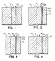
- Fig. 1 of the drawings shows the structure of a typical winter film involving a substrate 10 with an optical coating 20 carried on one surface 11 of the substrate 10.
- the optical coating 20 comprises a first layer of transparent dielectric material 21, a thin layer 22 of a reflecting metal material and a layer 23 of transparent dielectric material formed over the layer 22 of metal material.
- High optical transmittance in the visible is achieved by designing the thicknesses of the dielectric layers 21 and 23 to provide a high degree of induced transmittance through the optical coating 20.
- the overall optical and thermal performance of the energy control sheet is highly dependent on the physical and optical characteristics of the metal layer 22 and the dielectric layers 21 and 23.
- the dielectric layers 21 and 23 preferably have a high index of refraction (greater than 1.8) as well as high transparency (i.e. low absorption).
- the metal layer 22 be made as thin as possible.
- the metal layer 22 be a continuous metal film with low electrical resistivity. It is thus seen that the optical and thermal performance of the optical coating 20 involves conflicting performance factors, and thus materials and design optimization of the winter film coating is a challenging task.
- T V (%) is called the percent average daylight transmittance and is defined as the average percent transmittance over the visual wavelength range of 400-700 nanometers weighted against an illuminant source which approximates the noonday sun conditions and the photopic eye response curve.
- the performance factor T (%) represents the percent solar transmittance which is defined as the average percent transmittance over the wavelength range of 0.35 microns to 2.2 microns weighted against Moon's AM 2 Solar Curve.
- e represents the front thermal emittance which is defined as the total hemispherical emittance of the film measured from the coated surface at a temperature of approximately 20°C.
- the color factors are the apparent visual color of the film as perceived with visible transmitted or (outside) reflected light.
- the weatherometer factor involves the test cycles set forth in Table 2 below.
- the objective of the weatherometer test is to determine the theoretical long-term life expectancy of the window film through accelerated exposure using an Atlas Model Ci-35 Weather-O-Meter".
- the humidity test involves exposing the energy control sheet to an environment with relative humidity in excess of 95% at a temperature of 50°C.
- the temperature test involves exposing the film to a dry atmosphere at 80°C. Failure of the film in the Weather-O-MeterTM, humidity, and temperature tests is defined as the time when the thermal emittance e has increased to a value twice its initial value, (before testing begins). Failure of the films also occurs when visible inspection shows coating failure due to separation or visual appearance degradation.
- the emittance increase failure criterion is based on the observation that the rate of degradation of the film is very substantial when the emittance value has reached a value twice that of the initial value and the initial value is S 0.2. This will be seen in data presented and discussed below. All of the performance criteria set forth in Table 1 are for an energy control sheet in the form shown in Fig. 1, with the optical coating 20 in an unprotected state, i.e. without any top coating or laminated coversheet applied thereto.
- the U.V. exposure in the Weather-O-MeterTM is calculated to have the equivalent exposure of 5.35 times that of U.V. exposure in Miami, Florida.
- Figs. 1-4 illustrate the characteristics of various designs of energy control sheets utilizing materials and structures in accordance with this invention.
- Fig. 1 shows an optical coating 20 formed on surface 11 of a substrate 10.
- the substrate 10 will be a flexible polymer sheet such as polyethylene terephthalate (PET) although a wide variety of other polymer substrate materials, such as polyethylene, polypropylene and polyacrylonitrile, could also be utilized.
- PET polyethylene terephthalate
- the invention could also be utilized in embodiments in which the optical coating 20 is formed directly on a substrate which forms a part of the glazing unit itself, i.e. with substrate 10 being a rigid sheet of either transparent glass or a polymer material.
- Each of the dielectric layers 21 and 23 comprises a mixed metal oxide layer having metal constituents of at least one lanthanide series metal and at least one transition or semiconductor metal and is characterized by substantial water vapor impermeability which imparts improved weatherability to the energy control sheet.
- the dielectric layers 21 and 23 comprise a mixed cerium oxide and tin oxide layer.
- each of the . dielectric layers 21 and 23 perferably has a thickness in the range of about 300 Angstroms to about 550 Angstroms with the first layer 21 generally put down at a thickness of about 500 Angstroms and the second layer 23 put down at a thickness in the above range which maximizes the visual transmittance through the overall film for this combination of layers.
- cerium-tin oxide layers have excellent adherence to polymer substrates and thus do not require the use of any separate adhesion layer on the substrate surface.
- the metal layer 22 may comprise either pure silver having a thickness in the range of about 75 to 150 Angstroms or, more preferably, an alloy of palladium and silver with the palladium concentration in the range of about one weight percent to about five weight percent.”
- the thickness of the silver-palladium alloy film 22 is preferably in the range of about 70-150 Angstroms. As depicted in the graph of Fig. 11, and as set forth in the Table 3 below, satisfactory overall winter film performance is achieved when relatively optimum concentrations of cerium and tin are utilized in the cerium-tin oxide dielectric layers 21 and 23 when either pure silver or an alloy of silver and palladium is utilized as the metal layer 22.
- Fig. 11 and Table 3 below also illustrate that the minimum performance criteria for a winter film is met when a silver-palladium alloy layer is utilized with other dielectric layers such as titanium dioxide due to the higher corrosion resistance of the silver-palladium alloy layer.
- a perferred embodiment of this version of the invention involves a combined use of cerium-tin oxide as the dielectric layers 21 and 23 and silver-palladium alloy as the metal layer 22, it should be understood that the invention also encompasses the use of cerium-tin oxide with other metals as the metal layer 22 and also the use of a thin layer of silver-palladium alloy in conjunction with other transparent dielectric materials for the dielectric layers 21 and 23.
- the optical characteristics of a thin film layer of silver-palladium alloy are not as good as the optical characteristics of a silver layer itself.
- a thin film layer of silver-palladium alloy becomes a continuous, low electrical resistivity film at a substantially lower thickness value than is required when depositing a silver film.
- the ability to utilize a thinner layer of the silver-palladium alloy offsets substantially the degradation in optical performance of the metal layer resulting from the use of palladium in the alloy layer.
- Fig. 2 illustrates an alternative version of this invention comprising a transparent substrate 30 and an optical coating 40 formed on one surface 31 of substrate 30.
- the optical coating 40 also comprises a pair of dielectric layers 41 and 4 3 with a composite metal layer 42 therebetween.
- the composite metal layer 42 comprises a first thin layer 42A of palladium, a layer 42B of silver and a second thin layer 42C of palladium.
- the palladium layers 42A and 42C are preferably formed to a thickness which causes the T 2 transmission of the substrate plus coating to drop by 5-30 percent. Although films of this thickness cannot be accurately measured, it is believed the thickness is in the range of about 5-25 Angstroms. The lower end of the palladium thickness range is preferred.
- the intermediate silver layer is preferably formed to a thickness in the range of about 60 Angstroms to about 100 Angstroms.
- the formation of the initial flash palladium layer 42A enables the formation of a continuous silver film at about 90% of the thickness required for a pure silver layer to become continuous.
- the grain size of the silver is also considerably reduced. Transmission electron microscope (TEM) photographs have revealed that silver in the presence of palladium has a grain size of about 60 Angstroms whereas pure silver films have a grain size of about 300 Angstroms.
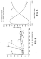
- the composite palladium-silver-palladium metal film 42 exhibits substantially the same improved weatherability as is exhibited by the silver palladium alloy film discussed above in connection with Fig. 1. This improved weatherability is shown in the graph of Fig.
- Fig. 3 illustrates another version of this invention which comprises a transparent substrate 50 and an optical coating 60 formed on one surface 51 of substrate 50.
- Optical coating 60 comprises a pair of transparent dielectric layers 61 and 63 with a composite thin film metal layer 62 therebetween.
- the composite layer 62 comprises a flash layer of palladium 62A and a layer of silver 62B formed over the flash palladium layer 62A.
- Fig. 4 illustrates an alternative winter film design which utilizes three layers of dielectric material in the optical coating 80 formed on substrate 70.
- the transparent dielectric layers 81 and 83 are high refractive index layers.
- the third transparent dielectric layer 84 may be, for example, a low index layer chosen for some special property that it may contribute to the overall winter film system.
- the second dielectric layer 83 will generally be formed as a thinner layer and the optical thickness of the composite of dielectric layers 83 and 84 will be such as to maximize the transmission of visible light through the winter film structure for this particular combination of layers.
- the thin metal layer 82 generally represents any of the silver-palladium alloy or composite layers discussed above in connection with Figs. 1-3.
- the transparent dielectric layers 81 and 83 are preferably mixed metal oxide layers as described above and in particular are preferably mixed cerium-tin oxide layers to achieve the optimum weatherability characteristics for the energy control sheet.
- the emissivity of the film had doubled to about 0.26 and the slope of the emissivity versus Weather-O-MeterTM hours curve is such that accelerated deterioration of the silver layer in the design had obviously begun to occur at this time.
- Curve D in Fig. 11 corresponds to Weather-O-MeterT' data on a energy control sheet utilizing mixed cerium-tin oxide (cerium and tin at respective 49:51 weight percents) for the dielectric layers and silver as the metal layer.
- This is coating design No. 3 in Table 3.
- the use of a cerium-tin oxide/silver design substantially improved the weatherability of the energy control sheet with coating failure at about 210 hours in the Weather-O-MeterTM.
- coating design No. 5 in Table 3 the flash layers of palladium on both sides of the silver were deposited to a thickness corresponding to a change in transmittance and the silver layer itself was formed to a thickness that resulted in a continuous metal layer.
- the coating design No. 6 in Table 3 utilized 3 weight % palladium and silver in the alloy metal film layer and the silver-palladium layer thickness was such that it formed a continuous metal layer.
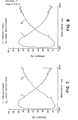
- Figs. 12-14 are graphs of the spectral transmittance and reflectance of energy control sheets utilizing the coating designs identified as numbers 4, 3 and 5 respectively in Table III above. The generally comparable optical performance of these coating designs is illustrated in these graphs. Each of the graphs shows that the coating designs achieve peak transmittance in the visual wavelength region between 400 and 700 nanometers and also have a fairly high transmittance band in the solar energy spectrum between 0.35 and 2.2 microns. These graphs further illustrate that the transmittance of the coating falls off very substantially in the far infrared region above 4 microns. While overall optical performance of coating designs using palladium along with silver in the metal layer are somewhat degraded from coating designs using silver alone, the amount of degradation is surprisingly small in view of the dramatically improved weatherability which is achieved. As previously stated, this is largely due to the ability to utilize thinner metal layers in the palladium-silver designs than is possible with a pure silver layer.
- Fig. 15 shows the theoretical spectral transmittance and reflectance for a winter film coating design of the type shown in Fig. 4 utilizing an outer dielectric layer 84 of silicon oxide.
- the dielectric layer 83 was formed from an oxide having a refractive index n approximately equal to 2.0 and has a physical thickness of about 300 Angstroms.
- the silicon oxide layer 84 has a thickness of about 300 Angstroms.
- a table of theoretical optical performance data for this four layer coating design is superimposed on the graph of Fig. 15 and illustrates that comparable optical performance can be achieved in such a four layer design.
- FIG. 16 shows calculated reflectance and transmittance curves for a theoretical four-layer coating design consisting of a Pd/Ag/Pd multilayer and an outer film of CeSnO and having a T of 35%.
- the palladium layer thicknesses are each 40 Angstroms
- the silver thickness is 120 Angstroms
- the CeSnO thickness is 300 Angstroms.
- the design has good selective properties, in particular comparatively high reflectance at the longer (non-visible) wavelengths, which provides good solar shading characteristics along with reasonably high daylight transmittance.
- the mixed metal oxide dielectric layers utilized in accordance with this invention may be formed using a variety of methods. Separate sources of lanthanide series metal oxide and a transition or semiconductor metal oxide may be co-evaporated to form the mixed metal oxide layer on the substrate. The relative evaporation rates of the two metal oxides may be adjusted to control the relative concentrations of the lanthanide series metal and the transition or semiconductor metal in the final dielectric film deposited on the substrate. Another approach that can be utilized is to mix the lanthanide series metal oxide and the transition or semiconductor metal oxide in a single evaporation source so that both the metal oxides are 'simultaneously evaporated from the single source. The relative concentrations of the two different metal oxides may be varied in the source mixture, taking into account the differences in vapor pressures and evaporation rates of the two different oxides, to control the final relative concentrations of respective metal constituents in the deposited mixed metal oxide layer.
- cerium and tin the compound cerium stannate may be formed. Cerium stannate may then be utilized as a single evaporation source. Although the cerium oxide and tin oxide evaporated from cerium stannate have slightly different evaporation rates, substantially constant relative weight percentages of cerium and tin in the deposited dielectric layer may be achieved by utilizing a continuous feed of fresh cerium stannate source material into the source crucible in the evaporation chamber.
- silver-palladium metal layers confer dramatically improved durability and weatherability to metal-dielectric optical coatings for use in energy control sheet systems involves two surprising factors. The first is that relatively small amounts of palladium, either in an alloy film or a composite metal film perform so well in stabilizing the primarily silver layer. The second is that the addition of small amounts of palladium to the primarily silver metal layer do not as drastically affect the desirable optical properties of the silver layer as would generally be expected from known characteristics of palladium.
- Palladium is known to be a "gray" metal, i.e. it does not have good optical properties in and of itself because of the nearly comparable values of the real and imaginary parts of the complex refractive index of palladium.
- the complex refractive index of a material is expressed as n-ik, where n is the real component of the refractive index and k is the extinction coefficient.
- the value of the ratio of k/n is generally utilized as an indication of the quality of the optical properties of the material. To obtain high transmittance values with a metal layer of any reasonable thickness the ratio k/n must be a large number.
- n and k values of materials such as silver and palladium are difficult and tend to be somewhat dependent on the thicknesses of the material, it is well known that the value of k/n for palladium is roughly two across the visible spectrum where the corresponding value of k/n for silver is a much larger number, approximately 60.
- the value of k/n for gold varies from about 2 to about 30 across the visible spectrum and is thus a good potential transmitter at longer visible wavelengths.
- silver-palladium alloy and composite films are not completely understood at this point, it appears that the use of a small amount of palladium in an alloy layer or as a flash layer prior to deposition of the silver layer causes the combined silver-palladium layer to have basically the micro-structural properties of palladium while having substantially the same optical properties as silver.
- Investigations, including transmission electron microscopic studies, performed to date indicate that the silver-palladium alloy and the palladium flash-silver films have a much finer grain structure than a silver layer, this finer grain structure being characteristic of a palladium layer.
- the silver-palladium alloy layers become continuous at a thickness of about 90% of that for a pure silver layer. Hence, the silver-palladium alloy and composite layers tend to nucleate in the same' manner as palladium.
- the small amounts of palladium in a silver-palladium alloy or composite film appear to substantially reduce the surface migration. of silver.
- the presence of palladium appears to immobilize the silver atoms and retain them in position on the underlying substructure.
- the combination of the smaller grain size and the film nucleation to continuity and low resistivity at lower thickness values enables a thinner overall metal film to be used in the metal-dielectric optical coating for winter film designs.
- the deterioration of the optical properties of the alloy film with the presence of palladium may be largely compensated for by using a thinner layer.
- the long term durability of the silver-palladium films may also be partly attributable to improved adhesion of the alloyed or composite metal layer to the underlying oxide layer.
- the small grains of the metal layer may indicate more bonding sites (i.e. nucleation sites) at the oxide interface for films prepared from silver and palladium than those prepared from silver alone.
Landscapes
- Chemical & Material Sciences (AREA)
- Life Sciences & Earth Sciences (AREA)
- Engineering & Computer Science (AREA)
- Chemical Kinetics & Catalysis (AREA)
- General Chemical & Material Sciences (AREA)
- Geochemistry & Mineralogy (AREA)
- Materials Engineering (AREA)
- Organic Chemistry (AREA)
- Inorganic Chemistry (AREA)
- Laminated Bodies (AREA)
Applications Claiming Priority (2)
| Application Number | Priority Date | Filing Date | Title |
|---|---|---|---|
| US06/433,511 US4565719A (en) | 1982-10-08 | 1982-10-08 | Energy control window film systems and methods for manufacturing the same |
| US433511 | 1999-11-03 |
Publications (2)
| Publication Number | Publication Date |
|---|---|
| EP0106223A2 true EP0106223A2 (de) | 1984-04-25 |
| EP0106223A3 EP0106223A3 (de) | 1985-05-15 |
Family
ID=23720395
Family Applications (1)
| Application Number | Title | Priority Date | Filing Date |
|---|---|---|---|
| EP83109641A Withdrawn EP0106223A3 (de) | 1982-10-08 | 1983-09-27 | Fensterenergiekontroll-Filmsysteme und Verfahren zu deren Herstellung |
Country Status (4)
| Country | Link |
|---|---|
| US (1) | US4565719A (de) |
| EP (1) | EP0106223A3 (de) |
| JP (1) | JPS59131449A (de) |
| CA (1) | CA1243523A (de) |
Cited By (2)
| Publication number | Priority date | Publication date | Assignee | Title |
|---|---|---|---|---|
| WO1990011975A1 (en) * | 1989-04-11 | 1990-10-18 | Andus Corporation | Transparent conductive coatings |
| CN106761320A (zh) * | 2016-12-29 | 2017-05-31 | 清华大学 | 一种基于半导体制冷制热的辐射窗户 |
Families Citing this family (46)
| Publication number | Priority date | Publication date | Assignee | Title |
|---|---|---|---|---|
| US4859532A (en) * | 1986-11-27 | 1989-08-22 | Asahi Glass Company Ltd. | Transparent laminated product |
| GB8719258D0 (en) * | 1987-08-14 | 1987-09-23 | Pilkington Glass Ltd | Glazine units |
| AU2721288A (en) * | 1987-10-21 | 1989-05-23 | Southwall Technologies, Inc. | Emi/rfi shield for visual display terminals |
| US4853264A (en) * | 1988-01-14 | 1989-08-01 | Southwall Technologies | Curved triple-pane glazing |
| JPH07100042B2 (ja) * | 1989-04-07 | 1995-11-01 | ワイケイケイ株式会社 | スライドファスナー用エレメント列の表面処理方法 |
| US5017419A (en) * | 1989-04-13 | 1991-05-21 | Chomerics, Inc. | Non-moire shielded window |
| US5084132A (en) * | 1989-04-13 | 1992-01-28 | Chomerics, Inc. | Non-moire' shielded window forming method |
| US5532062A (en) * | 1990-07-05 | 1996-07-02 | Asahi Glass Company Ltd. | Low emissivity film |
| US5419969A (en) * | 1990-07-05 | 1995-05-30 | Asahi Glass Company Ltd. | Low emissivity film |
| US5306547A (en) * | 1990-12-14 | 1994-04-26 | Southwall Technologies Inc. | Low transmission heat-reflective glazing materials |
| US5948497A (en) * | 1992-10-19 | 1999-09-07 | Eastman Kodak Company | High stability silver based alloy reflectors for use in a writable compact disk |
| US5320893A (en) * | 1992-12-31 | 1994-06-14 | Monsanto Company | Prelaminate with a partial cut to protect a solar coating from corrosion |
| AU6411894A (en) * | 1993-03-23 | 1994-10-11 | Southwall Technologies, Inc. | Gold-clad-silver-layer-containing films |
| US5510173A (en) * | 1993-08-20 | 1996-04-23 | Southwall Technologies Inc. | Multiple layer thin films with improved corrosion resistance |
| US5783360A (en) * | 1994-04-13 | 1998-07-21 | Flex Products, Inc. | Flexible optical medium with dielectric protective overcoat |
| CA2179853C (en) * | 1995-06-26 | 2007-05-22 | Susumu Suzuki | Laminate |
| US5908674A (en) * | 1995-12-13 | 1999-06-01 | E. I. Du Pont De Nemours And Company | Impact-resisting glazing structure |
| WO1997048107A1 (en) * | 1996-06-11 | 1997-12-18 | Sumitomo Osaka Cement Co., Ltd. | Transparent conductive film, low-reflection transparent conductive film, and display |
| FR2757151B1 (fr) | 1996-12-12 | 1999-01-08 | Saint Gobain Vitrage | Vitrage comprenant un substrat muni d'un empilement de couches minces pour la protection solaire et/ou l'isolation thermique |
| US6007901A (en) * | 1997-12-04 | 1999-12-28 | Cpfilms, Inc. | Heat reflecting fenestration products with color corrective and corrosion protective layers |
| US6391400B1 (en) | 1998-04-08 | 2002-05-21 | Thomas A. Russell | Thermal control films suitable for use in glazing |
| EP1127381B1 (de) | 1998-11-02 | 2015-09-23 | 3M Innovative Properties Company | Transparente leitfähige oxide für kunststoff-flachbildschirme |
| RU2135726C1 (ru) * | 1998-11-18 | 1999-08-27 | Савин Владимир Константинович | Оконный блок |
| US6699585B2 (en) * | 1998-12-18 | 2004-03-02 | Asahi Glass Company, Limited | Glazing panel |
| CN1145551C (zh) * | 1998-12-28 | 2004-04-14 | 旭硝子株式会社 | 层叠体及其制造方法 |
| US6294233B1 (en) | 1999-03-23 | 2001-09-25 | C P Films, Inc. | Edge-sealed window films and methods |
| US6090451A (en) * | 1999-03-23 | 2000-07-18 | Cpffilms, Inc. | Window film edge sealing method |
| DE19948839A1 (de) * | 1999-10-11 | 2001-04-12 | Bps Alzenau Gmbh | Leitende transparente Schichten und Verfahren zu ihrer Herstellung |
| US6887575B2 (en) * | 2001-10-17 | 2005-05-03 | Guardian Industries Corp. | Heat treatable coated article with zinc oxide inclusive contact layer(s) |
| US20060249245A1 (en) * | 2000-10-31 | 2006-11-09 | Bernard Balling | Ceramic and glass correction inks |
| US6936347B2 (en) * | 2001-10-17 | 2005-08-30 | Guardian Industries Corp. | Coated article with high visible transmission and low emissivity |
| US6997981B1 (en) * | 2002-05-20 | 2006-02-14 | Jds Uniphase Corporation | Thermal control interface coatings and pigments |
| US6933051B2 (en) * | 2002-08-17 | 2005-08-23 | 3M Innovative Properties Company | Flexible electrically conductive film |
| US7258757B2 (en) * | 2004-10-28 | 2007-08-21 | Film Technologies International, Inc. | Method of manufacturing an impact resistant and insulated glass unit composite with solar control and low-E coatings |
| US8507086B2 (en) * | 2006-12-21 | 2013-08-13 | 3M Innovative Properties Company | Seaming tape and method of sealing window film seams |
| US8574666B2 (en) * | 2006-12-21 | 2013-11-05 | 3M Innovative Properties Company | Method of imparting corrosion resistance to a multi-layer window film having a metal layer |
| BRPI0721299B1 (pt) * | 2006-12-28 | 2018-07-24 | 3M Innovative Properties Company. | Método para formação de um filme condutivo em um suporte de polímero flexível, filme condutivo e método para a fabricação de um artigo de vitrificação |
| GB2453343A (en) * | 2007-10-04 | 2009-04-08 | 3M Innovative Properties Co | Thermal infrared reflective paint composition |
| CN101939669A (zh) * | 2007-10-30 | 2011-01-05 | 3M创新有限公司 | 用于光学显示滤光片的带电磁干扰屏蔽的多层堆叠光学带通膜 |
| US8350451B2 (en) * | 2008-06-05 | 2013-01-08 | 3M Innovative Properties Company | Ultrathin transparent EMI shielding film comprising a polymer basecoat and crosslinked polymer transparent dielectric layer |
| DE102008051730A1 (de) | 2008-10-15 | 2010-04-22 | Saint-Gobain Sekurit Deutschland Gmbh & Co. Kg | Transparenter Gegenstand mit einem örtlich begrenzten, strukturierten, elektrisch beheizbaren, transparenten Bereich, Verfahren zu seiner Herstellung und seine Verwendung |
| PT2380234T (pt) | 2009-01-16 | 2018-10-18 | Saint Gobain | Antena transparente plana adequada para e emissão e receção de ondas eletromagnéticas, processo para o seu fabrico e utilização |
| DE102009025888B4 (de) | 2009-05-29 | 2014-04-10 | Saint-Gobain Sekurit Deutschland Gmbh & Co. Kg | Elektrisch großflächig beheizbarer, transparenter Gegenstand und seine Verwendung |
| KR20110033769A (ko) | 2009-09-25 | 2011-03-31 | (주)엘지하우시스 | 저방사 유리 및 이의 제조방법 |
| TW201330015A (zh) * | 2012-01-04 | 2013-07-16 | Mke Technology Co Ltd | 透明導電薄膜 |
| WO2020164735A1 (en) | 2019-02-15 | 2020-08-20 | Glas Trösch Ag | Functional coated article |
Family Cites Families (14)
| Publication number | Priority date | Publication date | Assignee | Title |
|---|---|---|---|---|
| US3034924A (en) * | 1958-10-30 | 1962-05-15 | Balzers Patent Beteilig Ag | Use of a rare earth metal in vaporizing metals and metal oxides |
| DE2309288C3 (de) * | 1973-02-24 | 1975-09-18 | W.C. Heraeus Gmbh, 6450 Hanau | Durchsichtige Scheibe, insbesondere Fensterscheibe, aus Glas oder Kunststoff mit wärmereflektierender, silberhaltiger Metallschicht und ihre Verwendung |
| US3978272A (en) * | 1974-03-13 | 1976-08-31 | Ppg Industries, Inc. | Coated article for solar control and process for its production |
| JPS5424983A (en) * | 1977-07-27 | 1979-02-24 | Teijin Ltd | Weathering resistant film for reflecting heat rays |
| US4235048A (en) * | 1978-01-03 | 1980-11-25 | Ppg Industries, Inc. | Reversible window unit for alternately reflecting and absorbing solar energy |
| JPS5944993B2 (ja) * | 1978-07-11 | 1984-11-02 | 帝人株式会社 | 積層体 |
| JPS5638251A (en) * | 1979-09-07 | 1981-04-13 | Teijin Ltd | Coated laminate |
| FR2474701A1 (fr) * | 1979-12-19 | 1981-07-31 | France Etat | Filtre optique interferentiel de protection contre les radiations infrarouges et application |
| JPS56164850A (en) * | 1980-05-26 | 1981-12-18 | Teijin Ltd | Manufacture of transparent conductive laminate |
| DE3039821A1 (de) * | 1980-10-22 | 1982-06-03 | Robert Bosch Gmbh, 7000 Stuttgart | Mehrschichtsystem fuer waermeschutzanwendung |
| US4321300A (en) * | 1980-11-12 | 1982-03-23 | Engelhard Minerals & Chemicals Corp. | Thin film solar energy collector |
| DE3169624D1 (en) * | 1980-12-26 | 1985-05-02 | Teijin Ltd | Selective light-transmitting laminate |
| DE3140100C2 (de) * | 1981-10-09 | 1986-11-27 | Robert Bosch Gmbh, 7000 Stuttgart | Mehrschichtsystem für Wärmeschutzanwendung |
| JPS5836448A (ja) * | 1982-03-09 | 1983-03-03 | 帝人株式会社 | 積層体 |
-
1982
- 1982-10-08 US US06/433,511 patent/US4565719A/en not_active Expired - Lifetime
-
1983
- 1983-09-27 EP EP83109641A patent/EP0106223A3/de not_active Withdrawn
- 1983-10-07 CA CA000438605A patent/CA1243523A/en not_active Expired
- 1983-10-08 JP JP58189137A patent/JPS59131449A/ja active Pending
Cited By (2)
| Publication number | Priority date | Publication date | Assignee | Title |
|---|---|---|---|---|
| WO1990011975A1 (en) * | 1989-04-11 | 1990-10-18 | Andus Corporation | Transparent conductive coatings |
| CN106761320A (zh) * | 2016-12-29 | 2017-05-31 | 清华大学 | 一种基于半导体制冷制热的辐射窗户 |
Also Published As
| Publication number | Publication date |
|---|---|
| JPS59131449A (ja) | 1984-07-28 |
| EP0106223A3 (de) | 1985-05-15 |
| US4565719A (en) | 1986-01-21 |
| CA1243523A (en) | 1988-10-25 |
Similar Documents
| Publication | Publication Date | Title |
|---|---|---|
| CA1243523A (en) | Energy control window film systems and methods for manufacturing the same | |
| US6783861B2 (en) | Glazing panel | |
| EP1150928B1 (de) | Verglasungsscheibe | |
| US6340529B1 (en) | Glazing panel | |
| US6610410B2 (en) | Glazing panel | |
| EP0622645B1 (de) | Filter mit Dünnfilm-Beschichtigung und Herstellungsverfahren | |
| EP1558950B1 (de) | Infrarotreflektierende geschichtete struktur | |
| EP0751099B1 (de) | Beschichtetes Substrat | |
| US6699585B2 (en) | Glazing panel | |
| KR100250604B1 (ko) | 광학 간섭 필터 및 이의 제조방법 | |
| EP1861339B1 (de) | Beschichtungszusammensetzung mit sonneneigenschaften | |
| PL190502B1 (pl) | Płyta o regulowanej przepuszczalności promieniowania słonecznego, wielowarstwowa jednostka do oszkleń oraz sposób wytwarzania płyty o regulowanej przepuszczalności promieniowania słonecznego | |
| PL218193B1 (pl) | Szyba do oszklenia zawierająca układ powłokowy, jednostka podwójna oszklenia, sposób wytwarzania poddanej obróbce cieplnej szyby do oszklenia oraz zastosowanie wierzchniej warstewki powłokowej | |
| WO2000011502A1 (en) | Wavelength selective applied films with glare control | |
| PL178985B1 (pl) | Przezroczyste podloze, zwlaszcza szklane, wielowarstwowe i oszklenie o strukturze wielowarstwowej PL PL PL | |
| GB2052787A (en) | Heat-reflecting panels | |
| JPH07149545A (ja) | 日光及び/又は赤外線に作用する薄い皮膜の積層を備えた透明な基材 | |
| JP4013329B2 (ja) | 積層体および窓用ガラス積層体 | |
| CN107667011A (zh) | 太阳能控制膜 | |
| EP1147066B1 (de) | Verglasungsscheibe | |
| JPH08304601A (ja) | 高視感透過率、低ソーラーファクター及び反射における中性外観を有する被覆基体 | |
| US4348453A (en) | Glazing possessing selective transmission and reflection spectra | |
| JP2576662B2 (ja) | 熱線遮断ガラス | |
| JPH03187736A (ja) | 熱線遮断ガラス | |
| PL199886B1 (pl) | Panel oszkleniowy i sposób wytwarzania panelu oszkleniowego |
Legal Events
| Date | Code | Title | Description |
|---|---|---|---|
| PUAI | Public reference made under article 153(3) epc to a published international application that has entered the european phase |
Free format text: ORIGINAL CODE: 0009012 |
|
| AK | Designated contracting states |
Designated state(s): AT BE CH DE FR GB IT LI LU NL SE |
|
| PUAL | Search report despatched |
Free format text: ORIGINAL CODE: 0009013 |
|
| AK | Designated contracting states |
Designated state(s): AT BE CH DE FR GB IT LI LU NL SE |
|
| STAA | Information on the status of an ep patent application or granted ep patent |
Free format text: STATUS: THE APPLICATION IS DEEMED TO BE WITHDRAWN |
|
| 18D | Application deemed to be withdrawn |
Effective date: 19860116 |
|
| RIN1 | Information on inventor provided before grant (corrected) |
Inventor name: HIGGINS, PATRICK K. Inventor name: PHILLIPS, ROGER W. Inventor name: BERNING, PETER H. |