EP0106427A1 - Procédé et appareil pour courber le bois - Google Patents
Procédé et appareil pour courber le bois Download PDFInfo
- Publication number
- EP0106427A1 EP0106427A1 EP83302909A EP83302909A EP0106427A1 EP 0106427 A1 EP0106427 A1 EP 0106427A1 EP 83302909 A EP83302909 A EP 83302909A EP 83302909 A EP83302909 A EP 83302909A EP 0106427 A1 EP0106427 A1 EP 0106427A1
- Authority
- EP
- European Patent Office
- Prior art keywords
- die surface
- laminate
- female die
- band
- strip
- Prior art date
- Legal status (The legal status is an assumption and is not a legal conclusion. Google has not performed a legal analysis and makes no representation as to the accuracy of the status listed.)
- Ceased
Links
- 239000002023 wood Substances 0.000 title claims abstract description 17
- 238000000034 method Methods 0.000 title claims description 14
- 238000005452 bending Methods 0.000 title claims description 3
- 239000000853 adhesive Substances 0.000 claims abstract description 14
- 230000001070 adhesive effect Effects 0.000 claims abstract description 14
- 239000002648 laminated material Substances 0.000 claims description 19
- 239000000463 material Substances 0.000 claims description 11
- 230000005855 radiation Effects 0.000 claims description 5
- 238000004519 manufacturing process Methods 0.000 claims description 4
- 238000000465 moulding Methods 0.000 abstract description 12
- 238000003825 pressing Methods 0.000 abstract description 3
- 230000015572 biosynthetic process Effects 0.000 description 3
- 230000003796 beauty Effects 0.000 description 2
- 239000007795 chemical reaction product Substances 0.000 description 2
- 238000010276 construction Methods 0.000 description 2
- 239000004677 Nylon Substances 0.000 description 1
- 239000003292 glue Substances 0.000 description 1
- 238000007689 inspection Methods 0.000 description 1
- 239000002184 metal Substances 0.000 description 1
- 238000012986 modification Methods 0.000 description 1
- 230000004048 modification Effects 0.000 description 1
- 229920001778 nylon Polymers 0.000 description 1
- 239000000047 product Substances 0.000 description 1
- 239000000126 substance Substances 0.000 description 1
Images

Classifications
-
- B—PERFORMING OPERATIONS; TRANSPORTING
- B27—WORKING OR PRESERVING WOOD OR SIMILAR MATERIAL; NAILING OR STAPLING MACHINES IN GENERAL
- B27D—WORKING VENEER OR PLYWOOD
- B27D1/00—Joining wood veneer with any material; Forming articles thereby; Preparatory processing of surfaces to be joined, e.g. scoring
- B27D1/04—Joining wood veneer with any material; Forming articles thereby; Preparatory processing of surfaces to be joined, e.g. scoring to produce plywood or articles made therefrom; Plywood sheets
- B27D1/08—Manufacture of shaped articles; Presses specially designed therefor
-
- Y—GENERAL TAGGING OF NEW TECHNOLOGICAL DEVELOPMENTS; GENERAL TAGGING OF CROSS-SECTIONAL TECHNOLOGIES SPANNING OVER SEVERAL SECTIONS OF THE IPC; TECHNICAL SUBJECTS COVERED BY FORMER USPC CROSS-REFERENCE ART COLLECTIONS [XRACs] AND DIGESTS
- Y10—TECHNICAL SUBJECTS COVERED BY FORMER USPC
- Y10T—TECHNICAL SUBJECTS COVERED BY FORMER US CLASSIFICATION
- Y10T156/00—Adhesive bonding and miscellaneous chemical manufacture
- Y10T156/10—Methods of surface bonding and/or assembly therefor
- Y10T156/1002—Methods of surface bonding and/or assembly therefor with permanent bending or reshaping or surface deformation of self sustaining lamina
- Y10T156/1043—Subsequent to assembly
- Y10T156/1044—Subsequent to assembly of parallel stacked sheets only
Definitions
- the invention relates to a method and apparatus for making a strip of laminated material, and the strip so produced, having a three dimensional configuration.
- the invention is particularly applicable to the formation of wood veneer for furniture making and the like, as for decorative molding strips provided on such furniture.
- veneer strips are formed by forming flat blankets which are cut into strips and jointed, or otherwise acted upon, in order to form the strips into the desired configuration, such as a molding on a piece of furniture.
- desired configuration such as a molding on a piece of furniture.
- prior art proposals to make laminated structures having three dimensional configurations e.g. see U.S. patents 3,027,923 and 3,063,483 however such proposals do not lend themselves to the formation of a wide variety of shapes and configurations to veneer strips, such as are used for molding for pieces of furniture and the like.
- I propose an apparatus for making a strip of laminated material comprising: a first roller rotatable about a first axis, a second roller rotatable about a second axis, a female die surface, a male die surface, a flexible band of substantially non-deformable material, means for attaching the ends of said flexible band to said rollers, and means for applying a force to said male die surface moving it toward said female die surface, characterized by said second axis being non-parallel with said first axis, said female die surface extending continuously from said first roller to said second roller, said male die surface conforming to a central area of said female die surface between said first and second rollers, and having a length substantially less than the length of said female die surface, said band having a length greater than the length of said female die surface extending between said rollers, and means for rotating said rollers about their axes of rotation with the band held thereby to tension said band and cause said band to closely conform to the shape of said female die surface.
- the strips of laminated material produced according to the present invention have first and second generally perpendicular portions, and a third portion generally perpendicular to both the first and second portions.
- the term "generally perpendicular” as used in the present specification and claims means that the portions are approximately perpendicular, although there is no requirements that they be exactly perpendicular, and in fact they may have a wide variety of configurations, depending upon ultimate use.
- a strip of laminated material such as a wood veneer strip
- a plurality of similarly shaped strips of material are placed together, with adhesive, to form a linear laminate.
- the linear laminate is bent to form a first portion, a second portion generally perpendicular to the first portion, and a third portion generally perpendicular to both the first and second portions.
- Thelaminate is held in the bent position during curing thereof, and after curing the laminate is released, providing a final strip of laminated material with first, second, and third mutually generally perpendicular portions.
- the strip of laminated material so produced may be fitted to a piece of furniture, providing decorative molding defining an edge of the piece of furniture.
- Apparatus for practising the invention comprises a first roller rotatable about a first axis and a second roller rotatable about a second axis, the second axis being distinctly non-parallel with the first axis.
- a female die surface extends
- a flexible band of substantially non-deformable material has a length greater than the length of the female die surface extending between the rollers, and means are provided for attaching the ends of the flexible band to the rollers. Means are provided for rotating the rollers about their axes of rotation with the band held thereby to tension the band and cause the band to closely conform to the shape of the female die surface.
- a male die member is placed over portions of the band, and a loading is applied thereto, in order to provide a force acting upon a central portion of the strips to hold them into contact with the female die surface.
- the strips to be formed into the strip of laminated material are placed between the female die surface and the band, the band applying a substantial pressure forcing portions of the strip exterior of the male die to conform to the shape of the female die surface.
- the first and second axes are preferably stationary with respect to each other.
- a strip of wood veneer produced according to the present invention includes first, second, and third mutually generally perpendicular portions, the strip being integral and having curved portions interconnecting the various perpendicular portions. Any number of additional further generally mutually perpendicular portions may be provided depending upon the desired ultimate shape and use of the formed strip.
- the invention relates to the formation of a final strip of laminated material, shown generally be reference numeral 10 in Figure 4, which may have a wide variety of configurations, and is particularly adaptable for use as molding for pieces of furniture and the like.
- the strip 10 according to the present invention is formed from a plurality of similarly shaped thin strips of wood, shown by reference numeral 11 in Figure 1.
- a suitable adhesive shown schematically by reference-numeral 12, is provided between each of the wood strips 11, and they are assembled together to form a linear laminate.
- the wood strips 11 would be between about 1/8 and 1/28 inches thick, and would normally be thin, on the order of about 1-4 inches.
- the strip width would be dictated by the smallest radius dimension necessary in the end product produced, a minimum radius of about 3/4 of an inch being possible.
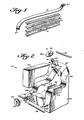
- a flexible band of substantially non-deformable material 13 is utilized in association with the apparatus 15 illustrated in FIGURES 2 and 3, to apply a force to the strips 11 during curing of the adhesive 12 to form an ultimate laminated strip 10.
- the band 13 preferably is of woven nylon or a material having like durability and inextensibility.
- the apparatus 15 is illustrated in FIGURES 2 and 3, and includes a first roller 17 rotatable about a first axis A-A, and a second roller 18 rotatable about a second axis B-B.
- A-A are stationary with respect to each other.
- the second axis is distinctly non-parallel to the first axis, normally being skew with respect to the first axis.
- the rollers 17, 18 are mounted for rotation with respect to a stationary component 20 by any suitable means, such as an arm and bushing (not shown) extending from the stationary block 20 and receiving the first shaft 22 associated with first roller 17, and another such structure receiving the second shaft 23 associated with the second roller i 18.
- a female die surface 25 extends continuously from the first roller 17 to the second roller 18, the end terminations of the surface 25 being substantially tangent to the rollers 17, 18.
- the construction of the female die surface 25, which is part of the stationary block 20, corresponds to the construction of the final strip of laminated material 10 to be formed.
- the length of the surface 25 is at least slightly greater than the length of the strip 10, and the length of the flexible band 13 is greater than the length of the surface 25.
- Means are provided for attaching the ends of the band 13 to the rollers 17, 18.
- the attachment of the ends of the band 13 to the rollers 17, 18 can be accomplished in any conventional manner, such as by providing a slot in each roller surface for receipt of a band end, a fastening material, or the like.
- One exemplary manner illustrated in the drawings comprises forming a plurality of openings 27 at each end of the band 13.
- Metal eyelets may be provided in the openings 27.
- the openings 27 are adapted to cooperate with projections extending radially from the surfaces of the rollers 17, 18, such as the projections 28 schematically illustrated in association with first roller 17 in FIGURE 2.
- the apparatus 15 further comprises means for rotating the rollers about their axes with the band 13 held thereby to tension the band and cause the band to closely conform to the shape of the die surface 25.
- the exemplary form of rotating-means illustrated in the drawings includes a passageway 30 in first shaft 22 adapted to receive a bar 32, an application of a force to the bar 32 resulting in rotation of the shaft 22, and thus the first roller 17.
- a pawl and ratchet arrangement also may be provided in order to hold the roller 17 into a position to which it has been moved to tension the band 13, a pawl and ratchet arrangement also may be provided.
- Pawl gear 33 having a keyway 34 formed therein is adaptd to fit over the shaft 22 and key 35 thereof, so that rotation of shaft 22 results in rotation of ratchet gear 33.
- a conventional pivotally mounted spring biased pawl 36 is mounted on block 20 for cooperation with the teeth of the gear 33 to hold the roller 17 in the position to which it has been rotated.
- a like pawl and ratchet arrangement is also associated with the second roller 18, including ratchet gear 38 having keyway 39, key 40 on shaft 23, interior passageway 41 through shaft 23, pawl 42, and bar 43.
- a male die component 50 is provided for cooperation with a portion of the female die surface 25.
- the male die component 50 has a surface, illustrated generally by reference numeral 51 in FIGURE 2, that corresponds exactly to a central portion of the female die surface 25.
- a pair of upwardly extending locating flanges 53 are preferably provided associated with the block 20 for receiving the die 50 therebetween.
- An apparatus for applying a clamping force tightly pressing the surface 51 toward engagement with the surface 25 (with the band 13 and strips 11 therebetween) is also provided. This clamping force may be provided by a hydraulic cylinder, as illustrated schematically by reference numeral 55 in FIGURE 3, by a manual screw clamp arrangement, or the like.
- the flanges 53 prevent unwanted movement of the block 50 with respect to the block 20.
- rollers 17, 18, and associated structures comprise means for applying tension to the band 13 exterior of the male die 50.
- a chemical cure accelerator could be utilized, or the glue could be exposed to a radiation source to facilitate cure.
- a source of microwave radiation illustrated generally by reference numeral 57 in FIGURE 3, can be provided in cooperation with the apparatus 15.
- Radiant heat, or other forms of heat could alternatively be utilized.
- the blocks 20, 50 (and the surfaces 25, 51 thereof) are formed of wood, and the fast cure radiation source 57 is a microwave source.
- the strips 11, with adhesive 12, therebetween are placed together to form a linear laminate.
- the linear laminate Before curing of the adhesive 12, the linear laminate is bent to form a first portion, a second portion generally perpendicular to the first portion, and a third portion generally perpendicular to both the first and second portions. This is accomplished by placing one face of the linear laminate in contact with a portion of the female die surface 25, placing the flexible band 13 over the linear laminate, and moving male die member 50 into the pdsition illustrated in FIGURE 3, pressing the laminate into the configuration defined by-the die surfaces 25, 51. The ends of the straps 13 are then brought into operative engagement with the rollers 17, 18 (as by the cooperating holes and projections 27, 28 interengaging), and the levers 32, 43 are rotated to tighten the band 13. This tightening action causes the strap 13 to bend the linear laminate so that the portions thereof exterior of male die 50 generally conforms to the female die surface 25.
- the laminate is held in its bent position during curing thereof (see FIGURE 3). Curing may be facilitated by exposure of the apparatus 15 to a fast-cure radiation source 57, such as a microwave source.
- a fast-cure radiation source 57 such as a microwave source.
- the final strip 10 has first, second, and third mutually generally perpendicular portions.
- first, second, and third mutually generally perpendicular portions For instance for the exact configuration of the strip 10 illustrated in FIGURE 4, either the portions 60, 61 can be considered a first portion, either of the portions 62, 63 can be considered a second portion, and the portion 64 can be considered a third portion.
- the final laminated strip produced has as a typical use thereof decorative molding for furniture.
- the strip 10 is provided as an edge configuration for a chair 66.
- the strip 10 is provided as an edge configuration for a chair 66.
- This compares to prior art processes wherein a number of individual strips would'be required, each strip being joined to its adjacent strips.
- the invention also allows a wide variety of configurations heretofore extremely difficult to produce to be readily constructed. Also, the beauty of the final article is enhanced since there is a continuous flow of grain of the veneer.
- a method and apparatus are provided for producing a strip of laminated material, such as wood veneer, the end strip having first, second, and third mutually generally perpendicular portions.
- the utilization of the strips according to the invention minimizes the number of joints, and thus costs associated with jointing, for the ultimate end product, and enhances the beauty of the final article produced (e.g. when used as decorative molding for a chair). While the invention has been herein shown and described in what is presently conceived to be the most practical and preferred embodiment thereof, it will be apparent to those of ordinary skill in the art that many modifications may be made thereof within the scope of the invention, which scope is to be accorded the broadest interpretation of the appended claims so as to encompass all equivalent methods, apparatus, and products.
Landscapes
- Engineering & Computer Science (AREA)
- Life Sciences & Earth Sciences (AREA)
- Manufacturing & Machinery (AREA)
- Mechanical Engineering (AREA)
- Wood Science & Technology (AREA)
- Forests & Forestry (AREA)
- Veneer Processing And Manufacture Of Plywood (AREA)
- Laminated Bodies (AREA)
- Inorganic Insulating Materials (AREA)
- Ceramic Capacitors (AREA)
- Finished Plywoods (AREA)
Applications Claiming Priority (2)
| Application Number | Priority Date | Filing Date | Title |
|---|---|---|---|
| US06/380,756 US4495019A (en) | 1982-05-21 | 1982-05-21 | Plywood bending |
| US380756 | 1982-05-21 |
Publications (1)
| Publication Number | Publication Date |
|---|---|
| EP0106427A1 true EP0106427A1 (fr) | 1984-04-25 |
Family
ID=23502311
Family Applications (1)
| Application Number | Title | Priority Date | Filing Date |
|---|---|---|---|
| EP83302909A Ceased EP0106427A1 (fr) | 1982-05-21 | 1983-05-20 | Procédé et appareil pour courber le bois |
Country Status (6)
| Country | Link |
|---|---|
| US (1) | US4495019A (fr) |
| EP (1) | EP0106427A1 (fr) |
| JP (1) | JPS5926202A (fr) |
| CA (1) | CA1232830A (fr) |
| DK (1) | DK222283A (fr) |
| NO (1) | NO831810L (fr) |
Cited By (3)
| Publication number | Priority date | Publication date | Assignee | Title |
|---|---|---|---|---|
| WO1998024602A1 (fr) * | 1996-12-05 | 1998-06-11 | Fredrik Torsteinsen | Objet stratifie et moule associe |
| DE10308628A1 (de) * | 2003-02-27 | 2004-09-16 | Markus Wassmer | Gegenstände, insbesondere Möbel, aus schichtverleimtem Bambus |
| CN112776104A (zh) * | 2021-02-08 | 2021-05-11 | 山东鑫鹏程木业加工有限公司 | 一种圆模板用液压成型机及方法 |
Families Citing this family (8)
| Publication number | Priority date | Publication date | Assignee | Title |
|---|---|---|---|---|
| US4816103A (en) * | 1987-04-21 | 1989-03-28 | Ethan Ernest | Process for manufacturing corrugated plywood composites |
| US4943339A (en) * | 1987-04-21 | 1990-07-24 | Ethan Ernest | Apparatus for manufacturing corrugated plywood composites |
| US5154486A (en) * | 1990-09-24 | 1992-10-13 | Westinghouse Electric Corp. | Furniture comprising laminated slats and methods of manufacturing such furniture |
| US5135142A (en) * | 1991-04-16 | 1992-08-04 | Tsai Chun F | Garment hanger made from compressed shaped plywood plate |
| JP3689907B2 (ja) * | 2001-04-27 | 2005-08-31 | 株式会社安中製作所 | 曲面状化粧ボードの曲面形成方法 |
| US20090220766A1 (en) * | 2008-03-03 | 2009-09-03 | L & P Property Management Company | Lightweight composite panel |
| CZ307401B6 (cs) * | 2017-05-17 | 2018-07-25 | ASPARA s.r.o. | Způsob kontinuální výroby vrstvených tvarovek z tenkých ohebných materiálů a zařízení k provádění tohoto způsobu |
| CN107243963A (zh) * | 2017-07-22 | 2017-10-13 | 福建双羿竹木发展有限公司 | 一种利用多层板成型框体结构的方法 |
Citations (8)
| Publication number | Priority date | Publication date | Assignee | Title |
|---|---|---|---|---|
| DE177312C (fr) * | ||||
| US687144A (en) * | 1901-08-31 | 1901-11-19 | George M Fenn | Frame for bending scythe-snaths. |
| US707221A (en) * | 1902-03-18 | 1902-08-19 | George Merrihue Fenn | Machine for bending scythe-snaths. |
| US966678A (en) * | 1910-01-10 | 1910-08-09 | Fred J Fisher | Bending-machine. |
| US1016684A (en) * | 1910-01-10 | 1912-02-06 | Fred J Fisher | Process for bending wood. |
| US3063483A (en) * | 1958-12-16 | 1962-11-13 | Harwood Cabinets Ltd | Forming machines for wood and like materials |
| US3107708A (en) * | 1960-08-15 | 1963-10-22 | Knoll Associates | Novel wood bending method |
| DE1728013B2 (de) * | 1968-08-13 | 1976-07-29 | Mayer, Xaver, 6800 Mannheim | Vorrichtung zum herstellen von gelaenderstaeben |
Family Cites Families (10)
| Publication number | Priority date | Publication date | Assignee | Title |
|---|---|---|---|---|
| US119393A (en) * | 1871-09-26 | Improvement in machines for bending wood | ||
| US728890A (en) * | 1903-03-28 | 1903-05-26 | George Merrihue Fenn | Machine for bending scythe-snaths. |
| US2073290A (en) * | 1935-12-19 | 1937-03-09 | Monroe M Teague | Fluid pressure veneer press |
| US2308453A (en) * | 1939-05-20 | 1943-01-12 | John F Neary Jr | Apparatus for manufacturing laminated material |
| US2322962A (en) * | 1939-12-23 | 1943-06-29 | Spalding A G & Bros Inc | Laminated article |
| US2401299A (en) * | 1942-10-03 | 1946-06-04 | Universal Moulded Products Cor | Molding and gluing press |
| NL105587C (fr) * | 1956-01-30 | |||
| US3833333A (en) * | 1972-11-06 | 1974-09-03 | G Britten | Press construction |
| US3835904A (en) * | 1973-04-05 | 1974-09-17 | J Sumner | Apparatus for laminating wooden strips |
| US4018642A (en) * | 1975-09-08 | 1977-04-19 | Macmillan Bloedel Limited | Microwave curing of alkaline phenolic resins in wood-resin compositions |
-
1982
- 1982-05-21 US US06/380,756 patent/US4495019A/en not_active Expired - Fee Related
-
1983
- 1983-05-18 DK DK222283A patent/DK222283A/da not_active Application Discontinuation
- 1983-05-20 JP JP58087795A patent/JPS5926202A/ja active Pending
- 1983-05-20 CA CA000428514A patent/CA1232830A/fr not_active Expired
- 1983-05-20 NO NO831810A patent/NO831810L/no unknown
- 1983-05-20 EP EP83302909A patent/EP0106427A1/fr not_active Ceased
Patent Citations (8)
| Publication number | Priority date | Publication date | Assignee | Title |
|---|---|---|---|---|
| DE177312C (fr) * | ||||
| US687144A (en) * | 1901-08-31 | 1901-11-19 | George M Fenn | Frame for bending scythe-snaths. |
| US707221A (en) * | 1902-03-18 | 1902-08-19 | George Merrihue Fenn | Machine for bending scythe-snaths. |
| US966678A (en) * | 1910-01-10 | 1910-08-09 | Fred J Fisher | Bending-machine. |
| US1016684A (en) * | 1910-01-10 | 1912-02-06 | Fred J Fisher | Process for bending wood. |
| US3063483A (en) * | 1958-12-16 | 1962-11-13 | Harwood Cabinets Ltd | Forming machines for wood and like materials |
| US3107708A (en) * | 1960-08-15 | 1963-10-22 | Knoll Associates | Novel wood bending method |
| DE1728013B2 (de) * | 1968-08-13 | 1976-07-29 | Mayer, Xaver, 6800 Mannheim | Vorrichtung zum herstellen von gelaenderstaeben |
Cited By (4)
| Publication number | Priority date | Publication date | Assignee | Title |
|---|---|---|---|---|
| WO1998024602A1 (fr) * | 1996-12-05 | 1998-06-11 | Fredrik Torsteinsen | Objet stratifie et moule associe |
| DE10308628A1 (de) * | 2003-02-27 | 2004-09-16 | Markus Wassmer | Gegenstände, insbesondere Möbel, aus schichtverleimtem Bambus |
| DE10308628B4 (de) * | 2003-02-27 | 2006-12-14 | Markus Wassmer | Verfahren zum Herstellen von abschnittsweise gebogenen Stäben |
| CN112776104A (zh) * | 2021-02-08 | 2021-05-11 | 山东鑫鹏程木业加工有限公司 | 一种圆模板用液压成型机及方法 |
Also Published As
| Publication number | Publication date |
|---|---|
| DK222283A (da) | 1983-11-22 |
| US4495019A (en) | 1985-01-22 |
| JPS5926202A (ja) | 1984-02-10 |
| NO831810L (no) | 1983-11-22 |
| DK222283D0 (da) | 1983-05-18 |
| CA1232830A (fr) | 1988-02-16 |
Similar Documents
| Publication | Publication Date | Title |
|---|---|---|
| EP0106427A1 (fr) | Procédé et appareil pour courber le bois | |
| DE602004008623T2 (de) | Stanzvorrichtungsgummituch | |
| JPS60157827A (ja) | 表張物品を製造する方法及び装置 | |
| US4622191A (en) | Method for manufacturing decorative molding | |
| WO1996025239A1 (fr) | Dispositif tendeur pour materiel souple de forme plane | |
| US4537810A (en) | Metallic endless press band having an embossed surface for use in double band presses in the manufacture of laminates | |
| EP0348831A2 (fr) | Procédé et appareil de fabrication de corps moulés en matière plastique durcissable | |
| EP1093915B1 (fr) | Blanchet d'impression avec des entailles pour repérage et méthode pour aligner le blanchet d'impression. | |
| EP0372510B1 (fr) | Dispositif de plaques de caoutchouc pour assembler des courroies à câbles d'acier ou pour réparer une courroie à câbles d'acier | |
| US3835904A (en) | Apparatus for laminating wooden strips | |
| DE60116325T2 (de) | Verbindungspresse | |
| EP0075641B1 (fr) | Matériau composite | |
| DE3736739C2 (fr) | ||
| US3976526A (en) | Preparation of curved composite panel containing a rigid foamed plastic | |
| JPH01267010A (ja) | 熱可塑性積層体を製造する方法 | |
| US4610837A (en) | Apparatus and method for forming a corrugated sheet from a flat thermoplastic sheet | |
| DE69929062T2 (de) | Dichtung für wärmetauscher und verfahren und vorrichtung zu deren herstellung | |
| DE3138560A1 (de) | "verfahren und vorrichtung zum falten und formen einer fortlaufenden kette von reissverschluss-kopplungselementkoerpern" | |
| DE69118502T2 (de) | Verfahren zum Bedrucken von Riemen nach der Transferdruck-Technik | |
| DE4437410A1 (de) | Vorrichtung zum Dichten eines Rohrlecks | |
| US3616012A (en) | Plastic laminates bending method | |
| EP0393384A1 (fr) | Dispositif pour assembler du placage | |
| JPS59118442A (ja) | ダブルタイミングベルトの製造方法 | |
| JPH09131817A (ja) | ハニカムパネルの端面処理方法 | |
| DE19729733C2 (de) | Vorrichtung zum Formen von bogenförmigen Werkstücken aus biegefähigem Material |
Legal Events
| Date | Code | Title | Description |
|---|---|---|---|
| PUAI | Public reference made under article 153(3) epc to a published international application that has entered the european phase |
Free format text: ORIGINAL CODE: 0009012 |
|
| AK | Designated contracting states |
Designated state(s): AT BE CH DE FR GB IT LI LU NL SE |
|
| 17P | Request for examination filed |
Effective date: 19841003 |
|
| RAP1 | Party data changed (applicant data changed or rights of an application transferred) |
Owner name: STOW & DAVIS FURNITURE COMPANY |
|
| RIN1 | Information on inventor provided before grant (corrected) |
Inventor name: OOG, RICHARD K. |
|
| 17Q | First examination report despatched |
Effective date: 19861203 |
|
| STAA | Information on the status of an ep patent application or granted ep patent |
Free format text: STATUS: THE APPLICATION HAS BEEN REFUSED |
|
| 18R | Application refused |
Effective date: 19880516 |
|
| RIN1 | Information on inventor provided before grant (corrected) |
Inventor name: OOG, RICHARD K. |