EP0106742A1 - Ausgabevorrichtung für abzutrennende Streifen - Google Patents
Ausgabevorrichtung für abzutrennende Streifen Download PDFInfo
- Publication number
- EP0106742A1 EP0106742A1 EP19830401857 EP83401857A EP0106742A1 EP 0106742 A1 EP0106742 A1 EP 0106742A1 EP 19830401857 EP19830401857 EP 19830401857 EP 83401857 A EP83401857 A EP 83401857A EP 0106742 A1 EP0106742 A1 EP 0106742A1
- Authority
- EP
- European Patent Office
- Prior art keywords
- wing
- cutting
- strip
- auxiliary wing
- opening
- Prior art date
- Legal status (The legal status is an assumption and is not a legal conclusion. Google has not performed a legal analysis and makes no representation as to the accuracy of the status listed.)
- Granted
Links
Images




Classifications
-
- B—PERFORMING OPERATIONS; TRANSPORTING
- B65—CONVEYING; PACKING; STORING; HANDLING THIN OR FILAMENTARY MATERIAL
- B65H—HANDLING THIN OR FILAMENTARY MATERIAL, e.g. SHEETS, WEBS, CABLES
- B65H35/00—Delivering articles from cutting or line-perforating machines; Article or web delivery apparatus incorporating cutting or line-perforating devices, e.g. adhesive tape dispensers
- B65H35/0006—Article or web delivery apparatus incorporating cutting or line-perforating devices
- B65H35/002—Hand-held or table apparatus
-
- A—HUMAN NECESSITIES
- A47—FURNITURE; DOMESTIC ARTICLES OR APPLIANCES; COFFEE MILLS; SPICE MILLS; SUCTION CLEANERS IN GENERAL
- A47K—SANITARY EQUIPMENT; ACCESSORIES THEREFOR, e.g. TOILET ACCESSORIES
- A47K10/00—Body-drying implements; Toilet paper; Holders therefor
- A47K10/24—Towel dispensers; Toilet paper dispensers
- A47K10/32—Dispensers for paper towels or toilet paper
- A47K10/34—Dispensers for paper towels or toilet paper dispensing from a web, e.g. with mechanical dispensing means
-
- B—PERFORMING OPERATIONS; TRANSPORTING
- B65—CONVEYING; PACKING; STORING; HANDLING THIN OR FILAMENTARY MATERIAL
- B65H—HANDLING THIN OR FILAMENTARY MATERIAL, e.g. SHEETS, WEBS, CABLES
- B65H2701/00—Handled material; Storage means
- B65H2701/10—Handled articles or webs
- B65H2701/11—Dimensional aspect of article or web
- B65H2701/112—Section geometry
- B65H2701/1123—Folded article or web
- B65H2701/11231—Fan-folded material or zig-zag or leporello
-
- Y—GENERAL TAGGING OF NEW TECHNOLOGICAL DEVELOPMENTS; GENERAL TAGGING OF CROSS-SECTIONAL TECHNOLOGIES SPANNING OVER SEVERAL SECTIONS OF THE IPC; TECHNICAL SUBJECTS COVERED BY FORMER USPC CROSS-REFERENCE ART COLLECTIONS [XRACs] AND DIGESTS
- Y10—TECHNICAL SUBJECTS COVERED BY FORMER USPC
- Y10T—TECHNICAL SUBJECTS COVERED BY FORMER US CLASSIFICATION
- Y10T225/00—Severing by tearing or breaking
- Y10T225/20—Severing by manually forcing against fixed edge
- Y10T225/215—With blade-edge guard
- Y10T225/216—Movable
-
- Y—GENERAL TAGGING OF NEW TECHNOLOGICAL DEVELOPMENTS; GENERAL TAGGING OF CROSS-SECTIONAL TECHNOLOGIES SPANNING OVER SEVERAL SECTIONS OF THE IPC; TECHNICAL SUBJECTS COVERED BY FORMER USPC CROSS-REFERENCE ART COLLECTIONS [XRACs] AND DIGESTS
- Y10—TECHNICAL SUBJECTS COVERED BY FORMER USPC
- Y10T—TECHNICAL SUBJECTS COVERED BY FORMER US CLASSIFICATION
- Y10T225/00—Severing by tearing or breaking
- Y10T225/20—Severing by manually forcing against fixed edge
- Y10T225/23—Zigzag-folded supply package
-
- Y—GENERAL TAGGING OF NEW TECHNOLOGICAL DEVELOPMENTS; GENERAL TAGGING OF CROSS-SECTIONAL TECHNOLOGIES SPANNING OVER SEVERAL SECTIONS OF THE IPC; TECHNICAL SUBJECTS COVERED BY FORMER USPC CROSS-REFERENCE ART COLLECTIONS [XRACs] AND DIGESTS
- Y10—TECHNICAL SUBJECTS COVERED BY FORMER USPC
- Y10T—TECHNICAL SUBJECTS COVERED BY FORMER US CLASSIFICATION
- Y10T225/00—Severing by tearing or breaking
- Y10T225/20—Severing by manually forcing against fixed edge
- Y10T225/238—With housing for work supply
- Y10T225/252—With brake or tensioner
- Y10T225/253—Restricted or restrictable work outlet
-
- Y—GENERAL TAGGING OF NEW TECHNOLOGICAL DEVELOPMENTS; GENERAL TAGGING OF CROSS-SECTIONAL TECHNOLOGIES SPANNING OVER SEVERAL SECTIONS OF THE IPC; TECHNICAL SUBJECTS COVERED BY FORMER USPC CROSS-REFERENCE ART COLLECTIONS [XRACs] AND DIGESTS
- Y10—TECHNICAL SUBJECTS COVERED BY FORMER USPC
- Y10T—TECHNICAL SUBJECTS COVERED BY FORMER US CLASSIFICATION
- Y10T225/00—Severing by tearing or breaking
- Y10T225/20—Severing by manually forcing against fixed edge
- Y10T225/238—With housing for work supply
- Y10T225/255—With internal guide
-
- Y—GENERAL TAGGING OF NEW TECHNOLOGICAL DEVELOPMENTS; GENERAL TAGGING OF CROSS-SECTIONAL TECHNOLOGIES SPANNING OVER SEVERAL SECTIONS OF THE IPC; TECHNICAL SUBJECTS COVERED BY FORMER USPC CROSS-REFERENCE ART COLLECTIONS [XRACs] AND DIGESTS
- Y10—TECHNICAL SUBJECTS COVERED BY FORMER USPC
- Y10T—TECHNICAL SUBJECTS COVERED BY FORMER US CLASSIFICATION
- Y10T225/00—Severing by tearing or breaking
- Y10T225/20—Severing by manually forcing against fixed edge
- Y10T225/276—Blade movable to severing position by moving work
- Y10T225/277—With simultaneous application of brake or clamp
- Y10T225/278—Applied to running length work
Definitions
- the invention relates to a reel of continuous strips to be cut, intended to allow the distribution of desired lengths of strip. It applies in particular for the distribution of paper strips, such as toilet paper, paper towels ...
- Tape dispensers comprising a housing in which the tape is housed, an opening for the outlet thereof and a cutting member which makes it possible to cut the tape after traction of the desired length; the strip is cut by applying it against the cutting member and by exerting on said strip a sudden suitable pull.
- the GB patent No. 1,516,097 and the US Patent No. 3,040,943 provide a movable cutting wing which causes the blocking of the strip when operating the sudden breaking tensile on it.
- the movable cutting wing has sharp means protruding from the reel, which prove in practice dangerous for users, especially for children (who may be injured in the face or in the eyes taking into account the usual height at which the reel opening is located).
- the present invention proposes to provide an improved solution to the problem of distributing continuous strips to be cut.
- An essential objective of the invention is in particular to provide a reel of simple structure, and therefore inexpensive, which is capable of generating a regular distribution, without waste or accidental tearing, allows a clean and frank cut of the strip at the desired lengths , and poses no danger to the user.
- the invention aims in particular, for the purpose of simplification, to ensure with the same member the soft braking effect without blocking during distribution, and the net blocking effect without slipping during cutting.
- Another object of the invention is to provide a reel benefiting both from a space requirement compatible with placement in sanitary rooms, in particular in public places, and of a considerably increased capacity compared to reels known.
- Another objective is to obtain, after each cut of the strip, a constant length of protrusion, then facilitating the gripping of the strip during the next dispensing operation and avoiding defusing the latter.
- Another objective is to ensure better hygienic protection of the strip inside the reel, by reducing the risks of soiling thereof by external contact.
- Another objective is to provide a dispenser suitable for easy loading, while having an inviolable nature with regard to unauthorized persons.
- the cutting wing can be substantially planar, its cutting means being constituted by a sawtooth cut formed on its extreme edge (opposite to its articulation); the second auxiliary wing then has a return arranged to be arranged in a plane substantially coinciding with the plane of the cutting wing in the natural rest position of said wings.
- the covering portion of the first auxiliary wing may advantageously have, opposite the opening, a weighted extension deviating from said guide wall; the ballast is adjusted to obtain a suitable pressure of the covering portion against the guide wall in order to ensure soft braking of the appropriate intensity on the strip.
- This embodiment is advantageous by its simplicity, because the rest or soft braking positions of the wings are obtained by the natural effect of their weight without additional return means.
- the housing is adapted to form, below the guide wall, a magazine capable of containing a strip in the folded-out accordion state.
- the cross section of such a reel can thus have relatively small dimensions: its width is slightly greater than that of the continuous strip (in particular approximately between 8 and 30 cm depending on the application) and its depth which corresponds to the distance separating the pleats from the strip, can be flexibly adjusted according to the application so that the housing forms an acceptable projection relative to the support against which it is leaning (in particular the depth can be approximately between 6 and 20 cm); the capacity of the reel can easily present very important values, simply by providing an appropriate height thereof.
- This height can easily go up to 1.5 meters without raising practical difficulties of de-positioning, due to the elongated, narrow and shallow shape of the reel, which in practice allows it to be very conveniently housed in the sanitary facilities in places accessible to the public (cinemas, restaurants, stations, airports, hospitals, public or private authorities).
- the dispenser shown by way of example in FIGS. 1, 2 and 3 is a large capacity dispenser intended for the distribution of lengths of paper used as a hand towel; it can be used in any sanitary area (public or private) which is expected to be frequented by a certain number of people.
- This reel comprises a housing 1 having the general shape of an elongated rectangular parallelepiped extending vertically and of total height - H - of approximately 85 cm, of width - 1 - of approximately 25 cm and of depth - p - d 'about 11 cm.
- This housing comprises in the upper part means 2 for strip distribution which will be described later; below these means 2, the box forms a magazine adapted to contain a strip of paper 4 whose width - l'- is slightly less than that of the reel (of the order of 24 cm) and which is folded in accordion with folds distant by a distance - e - slightly less than the depth - p - from the reel (of the order of 10 cm).
- the reel store has an example of a height of around 70 cm, which allows it to be accommodated an accordion-folded strip, with a total length of around 600 m.
- the housing 1 is formed of two parts which are articulated one on the other in the lower part: a box 5 of U-shaped cross section and a back plate 6 adapted to be fixed against a support, for example a wall wall . (To simplify the description, we will subsequently adopt as forward / backward direction the direction from the box 5 to the plate 6).
- the rear plate 6 has along its vertical longitudinal edges edges such as 6a, which overlaps the box 5 in the closed position.
- this rear plate is provided, on both sides, with lateral flanges such as 6b which are fixed by riveting on the returns 6 to.
- lateral flanges such as 6b which are fixed by riveting on the returns 6 to.
- the rear plate 6 is provided with a return 6c which supports the strip 4 arranged in the magazine, and with two lower lateral flanges 6d, fixed on either side on said return 6c and on the ledges 6a.
- the box 5 is constituted by a front wall 5a, two side walls 5b, 5c and an upper wall 5d which closes it in the upper part.
- the front wall has in the lower part a window 14 made of transparent material, which allows the attendant to know immediately whether the reel should be recharged or not.
- the box is articulated in the lower part by an axis 7 on the flanges 6d so as to be able to pivot forwards, as illustrated in FIG. 1.
- a rod 8 connects its side walls 5b and 5c and passes through lights in the form of circular buttonholes 9 made in the flanges. These lights 9 and the rod 8 act as angular stop means limiting the pivoting of the box 5 relative to the rear plate.
- the lights 9 have a length adapted to allow pivoting of the box by an angle of the order of 20 °, which makes it easy to load the magazine 3 in the open position.
- the front wall 5a of the box has a passage opening S having the shape of a rectangular slot extending immediately below the upper wall 5d of the housing, over the entire width of the wall frontal 5a.
- This slot is located in an ascending plane, that is to say in a vertical plane or inclined up to approximately 30 ° relative to the vertical.
- the means of distributing the strip are described below, assuming the housing is closed, so as to make it possible to specify the position of the members with respect to the passage opening S.
- a guide wall 10 is secured between the flanges 6b secured to the rear wall 6 and is associated, at the rear, with means for guiding the strip, constituted in the example by a tube 11 fixed between the flanges; this guide tube is arranged opposite the rear plate 6 to delimit a space P for routing the strip between the magazine 3 and the distribution means 2.
- the guide wall 10 has a substantially horizontal internal zone 10a, a threshold 10b located in the vicinity of the opening S near the lower edge thereof and, at the front, a lip 10c extending downwards. beyond this threshold.
- the lip 10c carries a threaded socket 11 called to receive a tamper-evident member 12 for fixing the front wall 5a to the lip 10c.
- the wall 5a has a hole 13 with a milled edge, which opens facing the socket 11;
- the fixing member 12 is constituted by a screw which has a sectional head, housed in the countersink of the hole 13; a recess made in the screw head makes it possible to maneuver the latter with a special key 15.
- a cutting wing 16 Between the flanges 6b, three wings are articulated: a cutting wing 16, a first auxiliary wing 17 and a second auxiliary wing 18; these wings extend from one flange to the other, substantially (apart from play) over the entire width of the box 5 and its opening S, so as to close the latter.
- the cutting wing 16 is articulated around a transverse axis X by means of two cylindrical pins which it comprises on either side of its upper edge. (By the term “transverse” is meant in the present application a direction extending in the direction of the width - 1 - of the box).
- the axis X of articulation of the cutting wing 16 is located in the vicinity and below the upper edge of the opening S, opposite the threshold 10b of the guide wall 10.
- the cutting wing 16 is substantially planar and carries along its lower edge a cutout 16a in the shape of a sawtooth, intended to play the role of cutting means.
- the cutting wing can pivot around the X axis from a natural rest position in which it comes to rest against the second auxiliary wing 18 by the effect of its weight, and a cutting position in which it comes to bear against the first auxiliary wing 17.
- the cutting wing 16 In the rest position, the cutting wing 16 is located in the vicinity of the plane of the opening S, while, in the cutting position, it projects opposite and at the outside of said opening.
- the first auxiliary wing 17 is articulated around an axis Y which in the example is common with the articulation axis around which the second auxiliary wing 18 pivots.
- This axis is formed by a transverse cylindrical rod carried on either side other by the flanges 6b.
- the first wing 17 is fixed to this rod by means of two lugs 19, while the second wing 18 is articulated around said rod by means of small lateral yokes 20 provided with suitable holes.
- the axis Y of articulation of these wings 17 and 18 is offset from the axis X and is located above and in the vicinity of the guide wall 10, at the rear and near the threshold 10b.
- the first auxiliary wing has essentially three portions: a covering portion 17a which extends on one side of its joint Y inwards of the housing in contact with the internal zone 10a, a stop portion 17b, located on the other side of the articulation Y and which extends, opposite the threshold 10b, in the vicinity of the upper edge of the opening S between this edge and the axis X, finally an ascending portion 17c of junction between the portion 17b and the portion 17a.
- the abutment portion 17b forms, in the direction of the opening S, a projection situated above the cutting wing 16 so that the latter comes to bear against the latter when it reaches the cutting position.
- the abutment portion 17b is extended by a return 17d oriented upwards in order to completely close the opening S.
- junction portion 17c is located at the rear of the cutting wing 16 and is connected to the abutment portion 17b by an elbow located above and behind the X axis.
- the covering portion 17a follows the shape of the internal zone 10a so as to delimit a path C of passage for the strip, at which the latter is braked by the friction exerted by this portion 17a; this portion 17a has a weighted extension 17e which departs from the wall 10a in order, on the one hand, to give a flared shape at the entrance to the passageway C, on the other hand, to allow an adjustment of the forces friction caused by the support of the portion 17a under the influence of gravity forces.
- the second auxiliary wing 18 has, in cross section, a height suitable for coming to rest on the threshold 10b under the effect of its weight (the height of a wing being defined by the distance separating its axis of articulation and its furthest extreme edge); moreover, the height of this wing 18 is much less than that of the cutting wing 16.
- this wing 18 has a return 18a which extends it upwards and backwards by means of a bent edge 18b.
- This return has an angular direction such that it comes to join with the cutting wing in the natural position of rest, the plane of said return and that of the wing 16 coIncidant substantially at rest (apart from the thickness of the material).
- the cutting wing 16 has, in cross section, a height less than the distance separating, in the natural position of rest, the edge 18b of the wing 18 and the axis of articulation X of the wing of chopped off.
- the cutting wing 16 rests against the return 18a of the wing 18 without protruding from said wing, its cutting means 16a being contiguous against the return and disappearing, in a harmless state, against the upper side of this return.
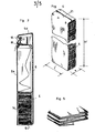
- Figure 4 shows a strip 4 according to the invention; this strip is formed by a continuous length of paper (or other material to be cut), which is packaged in an accordion folded state; as shown in Figure 5, the different folds are substantially superimposed in two parallel planes, so as to give the strip the shape of a rectangular parallelepiped. Once the strip is loaded in the reel, these planes are located in the vicinity respectively of da back plate 6 and of the front wall 5a.
- this envelope is torn in the upper part, the strip is installed in the reel magazine and its end is pushed back into the passageway C (thanks to a slight pivoting of the wing 17) until it exits between the auxiliary wing 18 and the threshold 10b.
- the box 5 can then be closed and locked: the reel is ready for use.
- FIGS 6a, 6b, 6c and 6d illustrate the operation thereof.
- Figure 6a shows the distribution means at rest.
- the strip passes between the second auxiliary wing 18 and the threshold 10c and protrudes outside the reel.
- the cutting wing 16a rests against the return 18a without risk for the users.
- Figure 6b shows the tape distribution phase: the user exerts continuous traction moderate nude on the end of the strip; it is braked by the first auxiliary wing 17 and is distributed regularly without the risk of tearing or waste. Depending on the direction of traction T, the wing 18 remains in place or lifts slightly.
- FIG. 6c illustrates an intermediate position of the dispensing means when the operator begins to exert an upward pull on the strip before reaching the cutting position.
- the wing 18 gradually disappears behind the cutting wing until the strip comes into contact with the cutting means 16a, which then come to protrude at the front of the opening S.
- FIG. 6d illustrates the cutting position: the user exerts an abrupt upward tensile strength R; the cutting wing 16, in abutment against the first auxiliary wing 17, transmits a moment M to the latter, which results in the appearance of a locking force B at the level of the covering portion 17a.
- the strip is blocked at this level and the traction R causes the clean and frank cut of the strip in contact with the cutting means.
- an overhang length - b - is preserved at the end of the strip, this length allowing easy gripping during the next distribution.
- the presence of the three wings and their arrangement eliminate the risks of defusing the strip, by preventing the paper from being able to be pushed back inwards, voluntarily or involuntarily.
- the reel described above by way of example has its own box; it is possible, as a variant in certain applications, that the housing of the reel is constituted by a housing formed in an already existing structure (in particular on vehicles or aircraft).
Landscapes
- Health & Medical Sciences (AREA)
- Public Health (AREA)
- Details Of Rigid Or Semi-Rigid Containers (AREA)
- Auxiliary Devices For And Details Of Packaging Control (AREA)
- Containers And Plastic Fillers For Packaging (AREA)
- Cartons (AREA)
Priority Applications (1)
| Application Number | Priority Date | Filing Date | Title |
|---|---|---|---|
| AT83401857T ATE20659T1 (de) | 1982-10-13 | 1983-09-23 | Ausgabevorrichtung fuer abzutrennende streifen. |
Applications Claiming Priority (4)
| Application Number | Priority Date | Filing Date | Title |
|---|---|---|---|
| FR8217420 | 1982-10-13 | ||
| FR8217420A FR2534565B1 (fr) | 1982-10-13 | 1982-10-13 | Devidoir de bandes continues a couper, en particulier bandes de papier |
| FR8301050A FR2539726A2 (fr) | 1983-01-21 | 1983-01-21 | Devidoir perfectionne de bandes continues a couper et bandes appelees a approvisionner ledit devidoir |
| FR8301050 | 1983-01-21 |
Publications (2)
| Publication Number | Publication Date |
|---|---|
| EP0106742A1 true EP0106742A1 (de) | 1984-04-25 |
| EP0106742B1 EP0106742B1 (de) | 1986-07-09 |
Family
ID=26223113
Family Applications (1)
| Application Number | Title | Priority Date | Filing Date |
|---|---|---|---|
| EP19830401857 Expired EP0106742B1 (de) | 1982-10-13 | 1983-09-23 | Ausgabevorrichtung für abzutrennende Streifen |
Country Status (4)
| Country | Link |
|---|---|
| US (1) | US4516711A (de) |
| EP (1) | EP0106742B1 (de) |
| DE (1) | DE3364437D1 (de) |
| ES (2) | ES8502401A1 (de) |
Cited By (2)
| Publication number | Priority date | Publication date | Assignee | Title |
|---|---|---|---|---|
| EP0409532A1 (de) * | 1989-07-20 | 1991-01-23 | Minnesota Mining And Manufacturing Company | Klingenschutz |
| KR100754390B1 (ko) * | 2005-12-08 | 2007-08-31 | 삼성전자주식회사 | 도광판 및 이를 채용한 백라이트 유니트 |
Families Citing this family (20)
| Publication number | Priority date | Publication date | Assignee | Title |
|---|---|---|---|---|
| SE458011B (sv) * | 1987-07-15 | 1989-02-20 | Holmens Bruk Ab | Pappershaallare med organ foer delning av en pappersbana i oenskade stycken |
| US4858806A (en) * | 1988-02-01 | 1989-08-22 | Schafer Christopher E | Ticket display and dispenser |
| US4995507A (en) * | 1988-12-16 | 1991-02-26 | Schafer Christopher E | Ticket dispensing structure |
| US5287980A (en) * | 1992-06-17 | 1994-02-22 | Eddy Associates, Inc. | Ticket dispenser assembly including interlocking dispenser units |
| US6039102A (en) | 1997-05-14 | 2000-03-21 | 3M Innovative Properties Company | Sheet material dispenser with safer sheet cutting means |
| FR2790126B1 (fr) * | 1999-02-24 | 2001-05-18 | Consumer Promotions Internat F | Distributeur de billets detachables d'une bande continue |
| MX2007007907A (es) * | 2004-12-29 | 2007-08-17 | Sca Hygiene Prod Ab | Un dispensador a manos libres de toallas de papel y sistema de distribucion. |
| DE102005030758B4 (de) | 2005-06-29 | 2008-12-11 | Kistner, Verena | Doppelspender für Einwegpapier |
| ES1063508Y (es) * | 2006-07-21 | 2007-07-01 | Martinez Miguel Gonzalez | Dispensador de papel higienico |
| JP2008055765A (ja) * | 2006-08-31 | 2008-03-13 | Seiko Instruments Inc | 用紙保持構造および電子投票装置用プリンタ |
| BR112014000728A2 (pt) * | 2011-07-13 | 2017-02-14 | Sca Hygiene Prod Ab | dispositivo distribuidor e pilha de produtos em folha |
| HUE026234T2 (en) | 2011-07-13 | 2016-06-28 | Sca Hygiene Prod Ab | Folded hygiene product stack |
| CN104736029A (zh) * | 2012-10-26 | 2015-06-24 | Sca卫生用品公司 | 分配器 |
| US10390664B2 (en) | 2012-10-26 | 2019-08-27 | Essity Hygiene And Health Aktiebolag | Separation unit and a dispenser comprising a separation unit |
| ES2986780T3 (es) | 2012-10-26 | 2024-11-12 | Essity Hygiene & Health Ab | Unidad de separación y dispensador que comprende una unidad de separación |
| RU2015121231A (ru) * | 2012-12-19 | 2017-01-26 | Ска Хайджин Продактс Аб | Раздаточное устройство и способ пополнения раздаточного устройства |
| US9970168B2 (en) * | 2014-04-22 | 2018-05-15 | Blane Alan Krause | Dog waste clean-up tool |
| WO2015167371A1 (en) * | 2014-04-28 | 2015-11-05 | Sca Hygiene Products Ab | Dispenser |
| HUE042182T2 (hu) * | 2014-06-19 | 2019-06-28 | Essity Hygiene & Health Ab | Z alakban hajtogatott szalagból álló köteg összekötõvel egy másik köteggel való összekapcsolódáshoz |
| US10134244B1 (en) * | 2018-05-03 | 2018-11-20 | Scientific Games International, Inc. | Lottery ticket dispenser bin with pivotal door |
Citations (1)
| Publication number | Priority date | Publication date | Assignee | Title |
|---|---|---|---|---|
| US3040943A (en) * | 1959-08-24 | 1962-06-26 | Edward L Bump | Material dispensing device |
Family Cites Families (4)
| Publication number | Priority date | Publication date | Assignee | Title |
|---|---|---|---|---|
| US444106A (en) * | 1891-01-06 | Paper-cutter | ||
| US2352445A (en) * | 1943-07-07 | 1944-06-27 | Arthur S Pinckney | Device for dispensing strip material |
| US2670041A (en) * | 1949-03-11 | 1954-02-23 | Derby Sealers Inc | Tape-dispensing mechanism with knife-guarding means |
| US3190520A (en) * | 1963-04-08 | 1965-06-22 | Gerald W Wyant | Cutter for non-woven fabric towel dispensers |
-
1983
- 1983-09-23 EP EP19830401857 patent/EP0106742B1/de not_active Expired
- 1983-09-23 DE DE8383401857T patent/DE3364437D1/de not_active Expired
- 1983-10-01 ES ES526191A patent/ES8502401A1/es not_active Expired
- 1983-10-12 US US06/541,038 patent/US4516711A/en not_active Expired - Fee Related
-
1984
- 1984-07-12 ES ES1984280622U patent/ES280622Y/es not_active Expired
Patent Citations (1)
| Publication number | Priority date | Publication date | Assignee | Title |
|---|---|---|---|---|
| US3040943A (en) * | 1959-08-24 | 1962-06-26 | Edward L Bump | Material dispensing device |
Cited By (2)
| Publication number | Priority date | Publication date | Assignee | Title |
|---|---|---|---|---|
| EP0409532A1 (de) * | 1989-07-20 | 1991-01-23 | Minnesota Mining And Manufacturing Company | Klingenschutz |
| KR100754390B1 (ko) * | 2005-12-08 | 2007-08-31 | 삼성전자주식회사 | 도광판 및 이를 채용한 백라이트 유니트 |
Also Published As
| Publication number | Publication date |
|---|---|
| ES280622Y (es) | 1985-09-01 |
| ES280622U (es) | 1985-02-16 |
| DE3364437D1 (en) | 1986-08-14 |
| EP0106742B1 (de) | 1986-07-09 |
| ES526191A0 (es) | 1985-01-16 |
| ES8502401A1 (es) | 1985-01-16 |
| US4516711A (en) | 1985-05-14 |
Similar Documents
| Publication | Publication Date | Title |
|---|---|---|
| EP0106742B1 (de) | Ausgabevorrichtung für abzutrennende Streifen | |
| CA1160653A (fr) | Distributeur de produits en feuille | |
| EP0808122B1 (de) | Spender von aufwischmaterial zur ausgabe in gefalzter oder in ungefalzter form | |
| CA2356758A1 (fr) | Dispositif de commande de sortie de lame de coupe d'un tambour dans un appareil distributeur de materiau d'essuyage | |
| EP1941821A1 (de) | Verteiler von nebeneinander angeordneten Rollen, der mit einer unteren Schiebeverschlussklappe ausgestattet ist | |
| EP3260029B1 (de) | Toilettenpapierrolle | |
| EP1951096B1 (de) | Papierspender | |
| WO2002066776A1 (fr) | Dispositif a volet flexible | |
| FR2585935A1 (fr) | Ensemble pour le conditionnement et la presentation d'au moins un produit solide, notamment d'au moins un pain de substance cosmetique | |
| WO2003056993A1 (fr) | Dispositif de controle et de repositionnement d'une bobine de materiaux d'essuyage dans un appareil de distribution a coupe automatique | |
| EP0130894A1 (de) | Behandlungseinrichtung für Personen | |
| CA1222229A (fr) | Devidoir perfectionne de bandes continues a couper | |
| FR2539726A2 (fr) | Devidoir perfectionne de bandes continues a couper et bandes appelees a approvisionner ledit devidoir | |
| EP0270736A1 (de) | Tragbarer Spender für das Aufbringen von zweiseitigem Klebeband | |
| FR2600991A1 (fr) | Distributeur d'elements minces empiles, muni d'un dispositif d'extraction de ces derniers, et boite-cartouche d'elements minces susceptible d'equiper un tel distributeur | |
| EP2816940B1 (de) | Vorrichtung zur ausgabe eines wischmaterials mit einer vorrichtung zur verhinderung des zurückrollens dieses materials nach dem herausziehen | |
| FR2534565A1 (fr) | Devidoir de bandes continues a couper, en particulier bandes de papier | |
| EP0330553A1 (de) | Spender für aufgerolltes hygienisches Handtuchband | |
| FR2751316A1 (fr) | Appareil distributeur de bandes de papier ouate pour essuie-mains, papier toilette et similaire | |
| FR2696433A1 (fr) | Distributeur de produit en bande. | |
| FR2651667A1 (fr) | Dispositif de protection hygienique pour sieges de w.c.. | |
| EP0783263A1 (de) | Toilettenpapierverpackung als einzeldosis | |
| LU83198A1 (fr) | Perfectionnements aux appareils de distribution de produits en rouleaux notamment d'essuie mains en papier | |
| EP0586272A1 (de) | Rollenpapierspender | |
| FR2539123A1 (fr) | Devidoir de bandes continues a couper, en particulier bandes de papier |
Legal Events
| Date | Code | Title | Description |
|---|---|---|---|
| PUAI | Public reference made under article 153(3) epc to a published international application that has entered the european phase |
Free format text: ORIGINAL CODE: 0009012 |
|
| AK | Designated contracting states |
Designated state(s): AT BE CH DE FR GB IT LI LU NL SE |
|
| 17P | Request for examination filed |
Effective date: 19840913 |
|
| GRAA | (expected) grant |
Free format text: ORIGINAL CODE: 0009210 |
|
| AK | Designated contracting states |
Kind code of ref document: B1 Designated state(s): AT BE CH DE FR GB IT LI LU NL SE |
|
| REF | Corresponds to: |
Ref document number: 20659 Country of ref document: AT Date of ref document: 19860715 Kind code of ref document: T |
|
| REF | Corresponds to: |
Ref document number: 3364437 Country of ref document: DE Date of ref document: 19860814 |
|
| ITF | It: translation for a ep patent filed | ||
| PG25 | Lapsed in a contracting state [announced via postgrant information from national office to epo] |
Ref country code: LU Free format text: LAPSE BECAUSE OF NON-PAYMENT OF DUE FEES Effective date: 19860930 |
|
| PLBE | No opposition filed within time limit |
Free format text: ORIGINAL CODE: 0009261 |
|
| STAA | Information on the status of an ep patent application or granted ep patent |
Free format text: STATUS: NO OPPOSITION FILED WITHIN TIME LIMIT |
|
| 26N | No opposition filed | ||
| REG | Reference to a national code |
Ref country code: FR Ref legal event code: ST |
|
| REG | Reference to a national code |
Ref country code: FR Ref legal event code: RC |
|
| REG | Reference to a national code |
Ref country code: FR Ref legal event code: DA |
|
| PGFP | Annual fee paid to national office [announced via postgrant information from national office to epo] |
Ref country code: BE Payment date: 19890831 Year of fee payment: 7 |
|
| PGFP | Annual fee paid to national office [announced via postgrant information from national office to epo] |
Ref country code: SE Payment date: 19890905 Year of fee payment: 7 Ref country code: CH Payment date: 19890905 Year of fee payment: 7 |
|
| PGFP | Annual fee paid to national office [announced via postgrant information from national office to epo] |
Ref country code: LU Payment date: 19890906 Year of fee payment: 7 |
|
| PGFP | Annual fee paid to national office [announced via postgrant information from national office to epo] |
Ref country code: NL Payment date: 19890930 Year of fee payment: 7 Ref country code: GB Payment date: 19890930 Year of fee payment: 7 |
|
| PGFP | Annual fee paid to national office [announced via postgrant information from national office to epo] |
Ref country code: AT Payment date: 19891004 Year of fee payment: 7 |
|
| PGFP | Annual fee paid to national office [announced via postgrant information from national office to epo] |
Ref country code: DE Payment date: 19891130 Year of fee payment: 7 |
|
| PG25 | Lapsed in a contracting state [announced via postgrant information from national office to epo] |
Ref country code: GB Effective date: 19900923 Ref country code: AT Effective date: 19900923 |
|
| PG25 | Lapsed in a contracting state [announced via postgrant information from national office to epo] |
Ref country code: SE Effective date: 19900924 |
|
| PG25 | Lapsed in a contracting state [announced via postgrant information from national office to epo] |
Ref country code: LI Effective date: 19900930 Ref country code: CH Effective date: 19900930 Ref country code: BE Effective date: 19900930 |
|
| BERE | Be: lapsed |
Owner name: BAREGE JACQUELINE Effective date: 19900930 |
|
| PG25 | Lapsed in a contracting state [announced via postgrant information from national office to epo] |
Ref country code: NL Effective date: 19910401 |
|
| NLV4 | Nl: lapsed or anulled due to non-payment of the annual fee | ||
| GBPC | Gb: european patent ceased through non-payment of renewal fee | ||
| REG | Reference to a national code |
Ref country code: CH Ref legal event code: PL |
|
| PG25 | Lapsed in a contracting state [announced via postgrant information from national office to epo] |
Ref country code: DE Effective date: 19910601 |
|
| REG | Reference to a national code |
Ref country code: FR Ref legal event code: ST |
|
| REG | Reference to a national code |
Ref country code: FR Ref legal event code: R1 |
|
| REG | Reference to a national code |
Ref country code: FR Ref legal event code: DS |
|
| EUG | Se: european patent has lapsed |
Ref document number: 83401857.4 Effective date: 19910527 |
|
| PGFP | Annual fee paid to national office [announced via postgrant information from national office to epo] |
Ref country code: FR Payment date: 20020913 Year of fee payment: 20 |