EP0130894A1 - Behandlungseinrichtung für Personen - Google Patents
Behandlungseinrichtung für Personen Download PDFInfo
- Publication number
- EP0130894A1 EP0130894A1 EP84401314A EP84401314A EP0130894A1 EP 0130894 A1 EP0130894 A1 EP 0130894A1 EP 84401314 A EP84401314 A EP 84401314A EP 84401314 A EP84401314 A EP 84401314A EP 0130894 A1 EP0130894 A1 EP 0130894A1
- Authority
- EP
- European Patent Office
- Prior art keywords
- bar
- cleat
- base
- bracket
- seat
- Prior art date
- Legal status (The legal status is an assumption and is not a legal conclusion. Google has not performed a legal analysis and makes no representation as to the accuracy of the status listed.)
- Ceased
Links
- 238000004873 anchoring Methods 0.000 claims description 6
- 238000005096 rolling process Methods 0.000 claims 1
- 230000036515 potency Effects 0.000 description 3
- 238000012550 audit Methods 0.000 description 2
- 230000000295 complement effect Effects 0.000 description 2
- 230000000903 blocking effect Effects 0.000 description 1
- 230000007547 defect Effects 0.000 description 1
- 238000010586 diagram Methods 0.000 description 1
- 239000004744 fabric Substances 0.000 description 1
- 238000009432 framing Methods 0.000 description 1
- 230000005484 gravity Effects 0.000 description 1
Images



Classifications
-
- A—HUMAN NECESSITIES
- A61—MEDICAL OR VETERINARY SCIENCE; HYGIENE
- A61G—TRANSPORT, PERSONAL CONVEYANCES, OR ACCOMMODATION SPECIALLY ADAPTED FOR PATIENTS OR DISABLED PERSONS; OPERATING TABLES OR CHAIRS; CHAIRS FOR DENTISTRY; FUNERAL DEVICES
- A61G7/00—Beds specially adapted for nursing; Devices for lifting patients or disabled persons
- A61G7/10—Devices for lifting patients or disabled persons, e.g. special adaptations of hoists thereto
- A61G7/1013—Lifting of patients by
- A61G7/1019—Vertical extending columns or mechanisms
-
- A—HUMAN NECESSITIES
- A61—MEDICAL OR VETERINARY SCIENCE; HYGIENE
- A61G—TRANSPORT, PERSONAL CONVEYANCES, OR ACCOMMODATION SPECIALLY ADAPTED FOR PATIENTS OR DISABLED PERSONS; OPERATING TABLES OR CHAIRS; CHAIRS FOR DENTISTRY; FUNERAL DEVICES
- A61G7/00—Beds specially adapted for nursing; Devices for lifting patients or disabled persons
- A61G7/10—Devices for lifting patients or disabled persons, e.g. special adaptations of hoists thereto
- A61G7/104—Devices carried or supported by
- A61G7/1044—Stationary fixed means, e.g. fixed to a surface or bed
-
- A—HUMAN NECESSITIES
- A61—MEDICAL OR VETERINARY SCIENCE; HYGIENE
- A61G—TRANSPORT, PERSONAL CONVEYANCES, OR ACCOMMODATION SPECIALLY ADAPTED FOR PATIENTS OR DISABLED PERSONS; OPERATING TABLES OR CHAIRS; CHAIRS FOR DENTISTRY; FUNERAL DEVICES
- A61G7/00—Beds specially adapted for nursing; Devices for lifting patients or disabled persons
- A61G7/10—Devices for lifting patients or disabled persons, e.g. special adaptations of hoists thereto
- A61G7/104—Devices carried or supported by
- A61G7/1046—Mobile bases, e.g. having wheels
-
- A—HUMAN NECESSITIES
- A61—MEDICAL OR VETERINARY SCIENCE; HYGIENE
- A61G—TRANSPORT, PERSONAL CONVEYANCES, OR ACCOMMODATION SPECIALLY ADAPTED FOR PATIENTS OR DISABLED PERSONS; OPERATING TABLES OR CHAIRS; CHAIRS FOR DENTISTRY; FUNERAL DEVICES
- A61G7/00—Beds specially adapted for nursing; Devices for lifting patients or disabled persons
- A61G7/10—Devices for lifting patients or disabled persons, e.g. special adaptations of hoists thereto
- A61G7/1049—Attachment, suspending or supporting means for patients
- A61G7/1059—Seats
-
- A—HUMAN NECESSITIES
- A61—MEDICAL OR VETERINARY SCIENCE; HYGIENE
- A61G—TRANSPORT, PERSONAL CONVEYANCES, OR ACCOMMODATION SPECIALLY ADAPTED FOR PATIENTS OR DISABLED PERSONS; OPERATING TABLES OR CHAIRS; CHAIRS FOR DENTISTRY; FUNERAL DEVICES
- A61G7/00—Beds specially adapted for nursing; Devices for lifting patients or disabled persons
- A61G7/10—Devices for lifting patients or disabled persons, e.g. special adaptations of hoists thereto
- A61G7/1073—Parts, details or accessories
- A61G7/1076—Means for rotating around a vertical axis
-
- A—HUMAN NECESSITIES
- A61—MEDICAL OR VETERINARY SCIENCE; HYGIENE
- A61G—TRANSPORT, PERSONAL CONVEYANCES, OR ACCOMMODATION SPECIALLY ADAPTED FOR PATIENTS OR DISABLED PERSONS; OPERATING TABLES OR CHAIRS; CHAIRS FOR DENTISTRY; FUNERAL DEVICES
- A61G7/00—Beds specially adapted for nursing; Devices for lifting patients or disabled persons
- A61G7/10—Devices for lifting patients or disabled persons, e.g. special adaptations of hoists thereto
- A61G7/1073—Parts, details or accessories
- A61G7/1082—Rests specially adapted for
- A61G7/1088—Back
Definitions
- the present invention relates to devices for handling people and more particularly those which make it easier to handle disabled or sick people.
- devices for handling people which essentially comprise a base surmounted by a bracket which itself supports an arm on which a seat is placed.
- the arm can generally be moved vertically relative to the bracket, for example by means of a jack.
- the base is generally itself mounted on casters allowing it to be moved so that people can be brought to the desired locations.
- the present invention aims to overcome these drawbacks, while realizing a handling device with a very simple structure therefore inexpensive, but making it very easy to handle people, such as disabled or sick people.
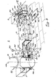
- the handling device shown in FIGS. 1 and 2 comprises a base 1 consisting of a piece advantageously in the form of an H comprising two lateral uprights 2 and 3 connected to each other by a middle wall 4.
- This H-shaped structure allows the base 1 to be able to present two open notches 5 and 6, respectively in the shape of a U on either side of the central wall 4 and delimited by the two portions of the lateral uprights 2 and 3 located on each side of the central wall 4
- this base 1 comprises means to be able to move it easily on a floor 7, such as for example four rollers 8.
- this base 1 defined more particularly by the two lateral uprights 2 and 3 and the median wall 4 define a first general plane 9, this plane 9 being substantially parallel to the ground on which the handling device must move when the device is in use.
- the device further comprises a bracket 10 comprising a foot 11 whose end 50 is fixed to the base 1 by any means.
- This bracket further comprises support means 12 in the embodiment of an arm 13 which is constituted by an axis of rotation.
- This bracket 10 essentially constituted by the foot 11, the support means 12 and the axis 13 are located substantially in a plane 14 which is advantageously perpendicular to the plane 9 defined above.
- the support means 12 are associated with the foot 11 by cylinder means, not shown, since they are well known in themselves. These actuator means make it possible to move the support means 12 relative to the foot 11 in order to be able to more easily lift the patient, as will be explained below and possibly bring him to places such as for example a bathroom above a bathtub.
- the support means 12 are constituted by swan neck to be able to more easily immerse the patient seated on this device
- this swan neck can partially wrap the edges of the bathtub in order to more easily bring the patient to the bottom thereof.
- actuator control means have been shown diagrammatically at 15.
- seating means 16 constituted by a U-shaped piece 17 between the lateral edges 51 and 52 of which is stretched, for example a canvas 18 making it possible to receive and support the patient.
- the lateral edges 51 and 52 of this U-shaped part 17 are terminated respectively by bearing means 19 and 20 which can pivot around this axis 13.
- a stop 21 capable of cooperating with a stop tab 22 extending on either side of this axis 13 so that the seat 16 can pivot in a rotation 23 (fig.2), around the axis 13 and take the two symmetrical positions on either side of the plane 14 as it appears clearly in FIG. 2.
- This stop 21 makes it possible to maintain the seat in a substantially horizontal position in its two positions and therefore to be able to support the patient so that he remains perfectly seated.
- this possible seat position in at least two symmetrical positions relative to the plane 14 which has been illustrated by means of rotation could also in certain cases be able to be constituted by translational slide grooves so as to be able to slide the following seat its plane so that it can take the two symmetrical positions on either side of the plane 14.
- the arm 13 could consist of two parallel axes so as to form a reference plane cooperating with symmetrical openings made on a lateral edge of the seat and the two symmetrical positions of the latter would be obtained by positioning the seat by turning it over and making the openings cooperate with its two axes.
- center bar 4 connecting the two lateral uprights 2 and 3 will advantageously be located on the plane 14.
- the handling device therefore comprises at least two bearing surfaces located on either side of the plane 14, these two surfaces appear respectively at 30 and 31 in FIG. 2. These two surfaces are represented in fact by the two upper parts and bottom of the H defining the base and they are located on either side of the axis passing through the middle wall 4 when the latter is located on the plane 14.
- the bearing surfaces 30 and 31 are chosen so that they have a value at least equal, if not greater than the value of the surface of the seat located on the same side of the plane 14 in order to constitute for the latter a polygon of lift above the surface capable of receiving the heavy body of a person in order to ensure the balance of the handling device for the safety of this person to be handled.
- the projection of the surface of the seat 16 on the bearing surfaces is contained therein so that the center of gravity which is essentially located on the person to be manipulated seated on the seat is projected into one or the other of these two bearing surfaces depending on whether the seat has one or the other of these two symmetrical positions relative to the plane 14.
- a slide 32 substantially perpendicular to the axis 13 and to the direction of the arm 12 so as to be able to receive a back 33 capable of being fixed by any means, in particular by pinching means 34 on the slide 32.
- This file can be positioned in different positions along this slide 32 to take all possible positions and at least as clearly appears in Figure 2, four in the illustrated embodiment. These four positions are defined according to the position of the person seated on the seat 16 and in order to be able to handle it more easily, as will be explained below.
- the seat 33 moves relative to the slide 32, but one can design an integrated system in which the backrest 33 is fixed to the slide 32, and it is then the assembly which can translate in grooves adapted relative to the support means 12.
- the device may include two files integrated into the slide 32 in order to be able to constitute a safety device to hold the patient in any way that he is seated on the seat 16 a files supporting the patient's back, the other serving as a support bar so that the patient can remain securely in his seat.
- this illustrates all the possible positions taken by the seat 16 and the backrest 33 in the case of the embodiment illustrated in FIG. 1.
- the position of the elements is shown in solid lines of the handling device in accordance with that which is illustrated in FIG. 1, that is to say in this case the patient is transported in a position as shown at 40.
- this device which has an advantage on this point compared to the device of the prior art, it is possible to be able to transport or take the patient to other positions.
- this device it is at least possible to position the patient in at least three other positions which are shown diagrammatically in dotted lines 41, 42 and 43.
- seat 16 may have a band of support fabric 18 in order to be able to position it more easily under the patient thanks to detachable means on either side on the lateral uprights 51 and 52.
- this seat is made up by other means, such as more comfortable cushions.
- handling in the vertical direction can be obtained by means of a jack so as, for example, to lift the patient from his bed and even to be able to bring him to the edge of a bathtub and immerse him in this one.
- the foot 11 is associated with the base 1 by rotation means 60 which make it possible to cause the stem (with its seat) to rotate by 180 ° relative to the base.
- the actuator is controlled to lift the patient as much as possible so that he can pass over the edges of the bathtub before rotating the bracket.
- the base 1 may include hooking means 61, for example on the lateral upright 2 opposite the lateral upright 3 on which the foot 11 of the bracket 10 is associated in order to be able to hang it for example on a staple located 62 in the ground and prevent the device from tipping over when the patient is outside the lift polygon defined by the base 1.
- the seat can be lowered so as to bring it with the patient to the bottom of the bath, this maneuver being facilitated by the swan neck shape 63 of the support means 12.
- the foot 11 will be fixed on the base 1 so that it is on a lateral side of this base 1, for example on one of the lateral uprights 3 of this base and substantially in the middle in order in particular to minimize the size of this handling device. Provision will also be made for blocking the stem to avoid internal rotation. pestives and maintain stability to the device.
- the length of the slide 32 will be determined so that the backrest can support the patient well and can take at least the four positions as shown in Figure 2, in this case the length of the slide 32 will be at least twice the width or depth of the seat, that is to say, the depth of the U-shaped part 17.
- FIGS 3 and 4 A, B, C show more particularly an embodiment of the attachment means to the ground of this handling device.
- FIG. 3 more specifically represents a part of the base 1 of the people handling device and more particularly the middle wall 4 connecting the two lateral arms 3 and 2.
- the hooking means 61 At the intersection of the middle wall 4 and the lateral arm 2, are arranged the hooking means 61.
- These hooking means 61 able to cooperate with an anchor plate 100 fixed to the ground, consist essentially of an anchor rod 101 which can slide in translation in, respectively two bearings 102 and 103, the end 104 of the anchor rod comprising two lugs 105, 106 able to cooperate with a complementary slot 107 made in the anchor plate 100 so that when these two lugs 105 and 106 enter this slot and undergo a rotation, they can come to be positioned, respectively on either side of the slot 107 and thus, avoid that one can perform a traction on the anchor rod 101 and separate it from the ground.
- the end 108 of the anchor rod 101 comprises a flat guide 109 cooperating with a rectangular groove 110 of the bearing 103.
- This flat guide 109 is defined over a certain length which is generally less than that of which the rod anchor can move in translation to come cooperate with the slot 107 made in the anchoring plate. This length is further defined so that a cylindrical part 111 surmounting this guide on the flat 109 can pivot in the rectangular groove 110 of the bearing 103.
- the top of the anchor rod 101 is terminated by a manipulation button 112 in order to be able, more easily, to control on the one hand the thrust of this anchor rod 101 so as to cause the lugs 105 and 106 to cooperate with the slot 107 and on the other hand make it undergo a rotation of at least 90 °.
- this anchor rod 101 is associated an eccentric 113 fixed on this rod. On this eccentric is exerted, by means of a spring 114, a thrust in this embodiment so that this spring tends to always raise the anchor rod 101 to move it away from the slot 107.
- the device further comprises, preferably arranged under the lower surface 200 of the middle wall 4, a copying bar 120 which can move in translation by sliding, respectively, for example in two bearings 121 and 122 constituted by stirrups fixed on the surface 200 of the central wall 4.
- a tension spring 123 With this copying bar 120, there is associated a tension spring 123, one end 124 of which is fixed to the central wall 4 and the other end of which is fixed via, for example, d 'a tab 126 to the feedback bar 120.
- a feeler finger 127 fixed integrally to this bar 120 and whose the lateral surface 227 is constantly pressed against the edge 228 of the eccentric 113.
- This finger has a sufficient length so that it is always in contact with the edge 228 of this eccentric 113 regardless of the position of the anchor rod enfon or not. This is moreover obtained by the action of the spring 123 which has the function of exerting a traction force on the copying bar 120 so as to constantly maintain this finger 127 against this edge 228 of the eccentric 113.
- the foot 11 of the bracket 10 and the rotation means 60 At the other end of the central wall 4, substantially at the intersection of the lateral arm 3 and of this central wall 4 are located the foot 11 of the bracket 10 and the rotation means 60 allowing the foot 11 of this bracket to be able to undergo rotations around an axis 130 which is generally perpendicular to the plane of the base, that is to say in fact to the ground on which must be move this people handling device.
- means 140 that can be locked-unlocked from the rotation of this foot.
- These means essentially comprise a tilting cleat 141 which can pivot about a substantially horizontal axis 142 which is fixed to a stirrup 143 welded under the underside 200 of the middle wall 4.
- This tilting cleat therefore essentially comprises two integral parts, located substantially on either side of this axis of rotation 142, of substantially parallelepiped shape.
- On the part 144 disposed on the side of the means of rotation 60 of the foot 11 of the bracket 10 is located one end 145 of a traction spring 146, the other end 147 of which is fixed to the lower surface 200 of the middle wall 4.
- this part 144 of the cleat 141 is determined so that it can come to cooperate in notches 150 or 151, as will be described below, produced in the bottom of the foot 11 of the bracket 10, these notches having a shape complementary to the external surface of the part 144 of the cleat 141.
- a handle 149 terminated by a grip handle 160.
- This handle 149 and / or this handle 160 are accessible by crossing, in this embodiment, the middle wall 4 for be able to be easily manipulated, by lights 161 and 162 sufficiently wide so that this handle 149 can be rotated, as illustrated in the figure by the arrow 163.
- the part 148 of the tilting cleat also has a length determined so that, as illustrated in the figure, when the anchor rod is in its rest or high position, that is to say not cooperating with the anchor plate 100 and therefore the finger 127 is furthest from the axis 164 of the anchor rod, the end 165 of the fill bar 120 is above a portion of the part 148 of the cleat tilting 141.
- the notches 150 and 151 have a different determined depth.
- the notch 151 being able to cooperate with the part 144 of the tilting cleat when the seat is above the base 1, while the notch 150 is it, able to cooperate with the part 148, when the seat is outside of the lift polygon of the people handling device.
- the depth of the notch 151 is sufficient for the tilting cleat 141, under the action of the spring 146, to completely release the two ends 170, 171, respectively from the part of the cleat 148 and 165 from the copying bar. , so that the end 165 comes above the end 148 of the tilting cleat as mentioned above.
- the other notch 150 has a lesser depth and is determined so that, when the foot has undergone a rotation of 180 ° (of course in this illustrated embodiment, that is to say that the patient, for example, has passed from the position above the base 1 to come to be positioned above a bathtub, the notch 150 can come to be located opposite the part 144 of the cleat 141, and that by a relatively small rotation this part 144 comes to be housed in the notch 150, but on the other hand, the end face 170 of the part 148 of the cleat 141 nevertheless remains at least partially opposite the face 171 of the end 165 of the copying bar 120.
- the embodiment illustrated in Figure 3 is particularly advantageous when the middle wall 4 is formed by a hollow profile for its lightness.
- an arrangement like the one illustrated will be adopted, that is to say that the assembly of the tilting cleat and of the copying bar 120 will be disposed under the lower face 200 of this median wall 4, while that the greater part of the anchor rod 101, in particular the eccentric 113, the pressure spring 114 with the finger 127, will be disposed inside this central wall 4.
- the finger 127 secured to the bar 120 crosses the lower surface 200 of this central wall 4 through an oblong hole 180, long enough to allow this finger to move to move away from or approach the rod. anchor 101.
- the rod 101 is in its high position and the finger 127 is pressed against the edge of the eccentric 113, and it is as far as possible from the axis of rotation 64 of the rod 101.
- the end 165 of the copying bar 120 is above the part 148 of the cleat 141.
- the cleat 141 comes, by its part 144, to cooperate in the bottom of the notch 151 which is the deepest.
- the loaded aid more particularly of the person, wants to rotate the bracket, it cannot, without the device being anchored in the ground to avoid any tilting. Indeed, without any particular action on, for example the anchor rod 101, the bracket 10, in particular by its foot, is prevented from pivoting since the notch 151 cooperates with the part 144 of the cleat 141 and that the latter cannot not rotate around a vertical axis. Under these conditions, it is then necessary for the aid to act on the rod 101 to bring the lugs 105, and 106, facing the longitudinal slot 107, then exert a pressure force in translation on this rod to make it slide guided.
- the anchoring rod can easily pivot by action on the button 112. This can pivot for example by 90 °, which means that the greatest thickness of the eccentric which repels finger 127, pivots and causes this finger 127 to approach the axis of rotation 164 of the anchor rod 101.
- the tension spring 123 keeps the finger 127 constantly pressed against the side wall of this eccentric 113 and drives in translation the copying bar 120, to bring it closer to the axis 164 mentioned above.
- the end 165 of the copying bar 120 emerges from the top of the part 148 of the cleat 141.
- the aid can then take the handle 149 and make it undergo a rotation such as that mentioned and shown diagrammatically, illustrated at 163 which in turn causes the rotation of the stopper 141 about its axis 142.
- This rotation of the stopper 141 releases the part 144 of the notch 151.
- This force on the handle 149 is carried out against the tension spring 146.
- the helper can then pivot the bracket 10 around its axis 130 to bring, as mentioned previously, the person above the bathtub. This is possible because as it appears in FIG. 4B, the part 144 of the cleat 141 is located below the plane of the lowest end of the foot 11 of the stem 10.
- the assistant responsible for this operation can release the handle-handle 149, and the latter under the action of the spring 146 will undergo an opposite rotation to the previous one so that the part 144 of the cleat 141 then comes to cooperate with the notch 150 which has come to be placed substantially in the path of this part 144.
- this notch 150 has a calculated depth and less than that of the notch 151, the cleat 141 cannot undergo a complete rotation to return to its original position, called the rest position, such as that illustrated in FIG. 4 A.
- the face 170 of the end of the part 148 of the cleat 141 remains substantially opposite the face 171 of the end 165 of the feedback bar 120 and thus prevents the feedback bar 120 from returning to its original position, as illustrated in FIG. 4 A.
- This arrangement is advantageous because, if inadvertently, when the person is manipulated above the bathtub, someone comes to disengage the seat by pivoting for example the anchor rod 101, this rotation would be prohibited since the finger 127 jams the eccentric, thus the copying bar is prevented from moving back by the part 148 of the cleat 141.
Landscapes
- Health & Medical Sciences (AREA)
- Nursing (AREA)
- Life Sciences & Earth Sciences (AREA)
- Animal Behavior & Ethology (AREA)
- General Health & Medical Sciences (AREA)
- Public Health (AREA)
- Veterinary Medicine (AREA)
- Invalid Beds And Related Equipment (AREA)
- Devices For Medical Bathing And Washing (AREA)
Applications Claiming Priority (4)
| Application Number | Priority Date | Filing Date | Title |
|---|---|---|---|
| FR8310369A FR2547722B1 (fr) | 1983-06-23 | 1983-06-23 | Dispositif de manutention de personnes |
| FR8310369 | 1983-06-23 | ||
| FR8319735 | 1983-12-09 | ||
| FR8319735A FR2556212B2 (fr) | 1983-12-09 | 1983-12-09 | Dispositif de manutention de personnes |
Publications (1)
| Publication Number | Publication Date |
|---|---|
| EP0130894A1 true EP0130894A1 (de) | 1985-01-09 |
Family
ID=26223495
Family Applications (1)
| Application Number | Title | Priority Date | Filing Date |
|---|---|---|---|
| EP84401314A Ceased EP0130894A1 (de) | 1983-06-23 | 1984-06-22 | Behandlungseinrichtung für Personen |
Country Status (2)
| Country | Link |
|---|---|
| US (1) | US4574410A (de) |
| EP (1) | EP0130894A1 (de) |
Cited By (1)
| Publication number | Priority date | Publication date | Assignee | Title |
|---|---|---|---|---|
| FR2610517A1 (fr) * | 1987-02-05 | 1988-08-12 | Jourdan Sa | Dispositif de manutention de personne |
Families Citing this family (12)
| Publication number | Priority date | Publication date | Assignee | Title |
|---|---|---|---|---|
| US4974905A (en) * | 1987-08-10 | 1990-12-04 | Davis John W | Chair bed |
| US5117516A (en) * | 1991-11-25 | 1992-06-02 | Elmer Penner | Patient sling |
| US5619762A (en) * | 1995-07-31 | 1997-04-15 | Mein; Jake | Apparatus for assisting a person in standing from a seated position |
| US5953774A (en) * | 1997-07-11 | 1999-09-21 | Arndt; Robert L. | Frontally insertable body hoist seat and sling assembly |
| KR101194388B1 (ko) | 2010-02-10 | 2012-10-24 | 한국생산기술연구원 | 회전 가능한 베드부가 구비된 이동용 리프트 장치 |
| KR101008944B1 (ko) | 2010-03-29 | 2011-01-17 | 한국생산기술연구원 | 링형 조작부가 구비된 리프트 장치 |
| KR101156170B1 (ko) * | 2010-04-01 | 2012-06-18 | 한국생산기술연구원 | 전복방지 시스템이 구비된 이동용 리프트 장치 |
| US8468623B2 (en) * | 2010-06-10 | 2013-06-25 | Richard A. Patterson | Lift chair |
| CA2941365A1 (en) * | 2015-09-08 | 2017-03-08 | Donald W. Wright | Hand truck with lift |
| US9731628B1 (en) * | 2016-01-25 | 2017-08-15 | Ford Global Technologies, Llc | Autonomous vehicle restraint selection |
| US9821681B2 (en) | 2016-01-25 | 2017-11-21 | Ford Global Technologies, Llc | Vehicle seat position sensing |
| CN110584925B (zh) * | 2019-09-20 | 2021-01-22 | 山东大学 | 一种病号护理装置 |
Citations (11)
| Publication number | Priority date | Publication date | Assignee | Title |
|---|---|---|---|---|
| DE1059620B (de) * | 1956-03-27 | 1959-06-18 | Anton Kirner | Geraet zum Hocheben von kranken Personen aus ihrem Bett |
| GB995235A (en) * | 1960-06-10 | 1965-06-16 | Frederick Charles Jenkins | Improvements relating to medical apparatus |
| CH470177A (de) * | 1968-05-22 | 1969-03-31 | Bengel Friedrich | Fahrbares Hebegerät, insbesondere für den Krankentransport |
| DE2408022A1 (de) * | 1974-02-20 | 1975-08-21 | Kuhn Goetz Gerd Prof Dr Med | Vorrichtung zum liften und manipulieren von gehbehinderten personen |
| DE2714358A1 (de) * | 1976-04-05 | 1977-10-27 | Soederberg Tollam Ab | Vorrichtung zum heben und senken von koerperbehinderten in und aus einem becken |
| FR2364648A1 (fr) * | 1976-09-20 | 1978-04-14 | Zk Edelstahlverarbeitung Gmbh | Support reglable en position pour handicapes physiques |
| US4253203A (en) * | 1979-09-04 | 1981-03-03 | Temco Products, Inc. | Folding transfer bench |
| GB2072139A (en) * | 1980-03-25 | 1981-09-30 | James Investments | Invalid hoists |
| DE3042683A1 (de) * | 1980-11-12 | 1982-07-08 | Blanc Gmbh & Co, 7519 Oberderdingen | Fahrbare behinderten-transporteinrichtung |
| EP0060941A1 (de) * | 1981-03-20 | 1982-09-29 | Linido B.V. | Badevorrichtung |
| GB2100979A (en) * | 1981-05-16 | 1983-01-12 | James Ind Ltd | Equipment for handling invalids and the disabled |
Family Cites Families (7)
| Publication number | Priority date | Publication date | Assignee | Title |
|---|---|---|---|---|
| US2679890A (en) * | 1951-09-24 | 1954-06-01 | Herman A Zannoth | Device for assisting invalids into and out of bathtubs |
| US2697475A (en) * | 1953-12-24 | 1954-12-21 | Albert J L Dueth | Bath lift |
| NL6803205A (de) * | 1968-03-06 | 1969-09-09 | ||
| GB1282274A (en) * | 1968-06-17 | 1972-07-19 | Mecanaids Ltd | Improvements in or relating to apparatus for handling disabled persons |
| DK131603C (da) * | 1971-07-08 | 1976-01-12 | Johansson Hans Arne Valentin | Lofte- og transportapparat til bevegelseshemmede |
| US3914808A (en) * | 1974-08-02 | 1975-10-28 | Int Medical Equipment And Supp | Lift and transport device |
| US4255823A (en) * | 1979-03-21 | 1981-03-17 | Adrion J. Boyer | Apparatus for moving and/or transporting loads |
-
1984
- 1984-06-20 US US06/622,806 patent/US4574410A/en not_active Expired - Fee Related
- 1984-06-22 EP EP84401314A patent/EP0130894A1/de not_active Ceased
Patent Citations (11)
| Publication number | Priority date | Publication date | Assignee | Title |
|---|---|---|---|---|
| DE1059620B (de) * | 1956-03-27 | 1959-06-18 | Anton Kirner | Geraet zum Hocheben von kranken Personen aus ihrem Bett |
| GB995235A (en) * | 1960-06-10 | 1965-06-16 | Frederick Charles Jenkins | Improvements relating to medical apparatus |
| CH470177A (de) * | 1968-05-22 | 1969-03-31 | Bengel Friedrich | Fahrbares Hebegerät, insbesondere für den Krankentransport |
| DE2408022A1 (de) * | 1974-02-20 | 1975-08-21 | Kuhn Goetz Gerd Prof Dr Med | Vorrichtung zum liften und manipulieren von gehbehinderten personen |
| DE2714358A1 (de) * | 1976-04-05 | 1977-10-27 | Soederberg Tollam Ab | Vorrichtung zum heben und senken von koerperbehinderten in und aus einem becken |
| FR2364648A1 (fr) * | 1976-09-20 | 1978-04-14 | Zk Edelstahlverarbeitung Gmbh | Support reglable en position pour handicapes physiques |
| US4253203A (en) * | 1979-09-04 | 1981-03-03 | Temco Products, Inc. | Folding transfer bench |
| GB2072139A (en) * | 1980-03-25 | 1981-09-30 | James Investments | Invalid hoists |
| DE3042683A1 (de) * | 1980-11-12 | 1982-07-08 | Blanc Gmbh & Co, 7519 Oberderdingen | Fahrbare behinderten-transporteinrichtung |
| EP0060941A1 (de) * | 1981-03-20 | 1982-09-29 | Linido B.V. | Badevorrichtung |
| GB2100979A (en) * | 1981-05-16 | 1983-01-12 | James Ind Ltd | Equipment for handling invalids and the disabled |
Cited By (1)
| Publication number | Priority date | Publication date | Assignee | Title |
|---|---|---|---|---|
| FR2610517A1 (fr) * | 1987-02-05 | 1988-08-12 | Jourdan Sa | Dispositif de manutention de personne |
Also Published As
| Publication number | Publication date |
|---|---|
| US4574410A (en) | 1986-03-11 |
Similar Documents
| Publication | Publication Date | Title |
|---|---|---|
| EP1644604B1 (de) | Zunge zum verbinden zweier verkleidungen einer flugzeugstruktur | |
| EP0680429B1 (de) | Faltbare einheit zum tragen oder transport einer person | |
| EP0059141B1 (de) | Rollstuhl mit Aufstehvorrichtung für einen Benutzer | |
| FR2524787A1 (fr) | Lit pour bebe | |
| FR2851211A1 (fr) | Siege rabattable et vehicule comportant un tel siege | |
| EP0228923A1 (de) | Umwandelbarer Rücksitz | |
| FR2799420A1 (fr) | Siege de vehicule | |
| FR2712914A1 (fr) | Ensemble pare-soleil, notamment pour la plage. | |
| EP0408407B1 (de) | Sitz mit umlegbarer Lehne | |
| EP0041411A1 (de) | Umwandelbarer Fahrzeugsitz mit schwenkbarem Sitzkissen und umklappbarer Rückenlehne, die gleichzeitig beweglich sind | |
| FR2501486A1 (fr) | Appuie-jambes, notamment pour vehicules de transport et plus particulierement pour aeronefs | |
| FR3047169A1 (fr) | Chaise | |
| FR2789142A1 (fr) | Mecanisme de reglage, et ensemble d'assise comportant un tel mecanisme | |
| EP0045679B1 (de) | Umwandelbarer Sitz | |
| EP0734665B1 (de) | Bettgestell, mit übereinander angeordneten abklappbaren Rahmen, das mit Bodenstützen ausgestattet ist | |
| WO2002071129A1 (fr) | Paire de lunettes a mecanisme d'ouverture automatique de branche | |
| CA2245907A1 (fr) | Fauteuil elevateur motorise | |
| EP0052031A1 (de) | In beschränktem Volumen und beschränkter Länge klappbarer Stuhl | |
| FR2725600A1 (fr) | Dispositif de montage articule pour un dossier de lit et lit ainsi equipe | |
| EP0276186A1 (de) | Vorrichtung zur Trägheitsverriegelung für Fahrzeugsitze | |
| FR2815527A1 (fr) | Lit a elements de barrieres coulissants et articules | |
| FR2562401A2 (fr) | Table a combinaisons multiples | |
| FR2556212A2 (fr) | Dispositif de manutention de personnes | |
| FR2712802A1 (fr) | Fauteuil élévateur motorisé. | |
| EP1622487B1 (de) | Bett mit verstellmitteln für die position eines barriereelements für matratzen |
Legal Events
| Date | Code | Title | Description |
|---|---|---|---|
| PUAI | Public reference made under article 153(3) epc to a published international application that has entered the european phase |
Free format text: ORIGINAL CODE: 0009012 |
|
| AK | Designated contracting states |
Designated state(s): AT BE CH DE GB IT LI LU NL SE |
|
| 17P | Request for examination filed |
Effective date: 19850319 |
|
| 17Q | First examination report despatched |
Effective date: 19860204 |
|
| STAA | Information on the status of an ep patent application or granted ep patent |
Free format text: STATUS: THE APPLICATION HAS BEEN REFUSED |
|
| 18R | Application refused |
Effective date: 19870510 |
|
| RIN1 | Information on inventor provided before grant (corrected) |
Inventor name: JOUK, LEO Inventor name: VIALLA, REMYECOLE NATIONALE D'ARTS ET METIERS Inventor name: LASSMANN, DIETER |