EP0106802A1 - Vorrichtung zum Ausstoss von Tröpfchen einer elektrisch leitenden Flüssigkeit - Google Patents
Vorrichtung zum Ausstoss von Tröpfchen einer elektrisch leitenden Flüssigkeit Download PDFInfo
- Publication number
- EP0106802A1 EP0106802A1 EP83810452A EP83810452A EP0106802A1 EP 0106802 A1 EP0106802 A1 EP 0106802A1 EP 83810452 A EP83810452 A EP 83810452A EP 83810452 A EP83810452 A EP 83810452A EP 0106802 A1 EP0106802 A1 EP 0106802A1
- Authority
- EP
- European Patent Office
- Prior art keywords
- electrode
- liquid
- support
- layer
- electrodes
- Prior art date
- Legal status (The legal status is an assumption and is not a legal conclusion. Google has not performed a legal analysis and makes no representation as to the accuracy of the status listed.)
- Granted
Links
- 239000007788 liquid Substances 0.000 title claims abstract description 34
- 230000005684 electric field Effects 0.000 claims abstract description 4
- 230000005499 meniscus Effects 0.000 claims description 7
- 230000003068 static effect Effects 0.000 claims description 2
- 230000015572 biosynthetic process Effects 0.000 description 7
- 238000010586 diagram Methods 0.000 description 5
- 238000000034 method Methods 0.000 description 5
- 238000004519 manufacturing process Methods 0.000 description 4
- 230000003993 interaction Effects 0.000 description 3
- 239000011159 matrix material Substances 0.000 description 3
- 229910052751 metal Inorganic materials 0.000 description 3
- 239000002184 metal Substances 0.000 description 3
- 230000003071 parasitic effect Effects 0.000 description 3
- 239000004020 conductor Substances 0.000 description 2
- 230000000694 effects Effects 0.000 description 2
- 239000003792 electrolyte Substances 0.000 description 2
- 230000000717 retained effect Effects 0.000 description 2
- 241001416092 Buteo buteo Species 0.000 description 1
- 238000003491 array Methods 0.000 description 1
- 230000005540 biological transmission Effects 0.000 description 1
- 239000012777 electrically insulating material Substances 0.000 description 1
- 230000005284 excitation Effects 0.000 description 1
- 238000010438 heat treatment Methods 0.000 description 1
- 238000010348 incorporation Methods 0.000 description 1
- 230000001939 inductive effect Effects 0.000 description 1
- 238000007641 inkjet printing Methods 0.000 description 1
- 238000009434 installation Methods 0.000 description 1
- 239000011810 insulating material Substances 0.000 description 1
- 239000000463 material Substances 0.000 description 1
- 238000004806 packaging method and process Methods 0.000 description 1
- BASFCYQUMIYNBI-UHFFFAOYSA-N platinum Chemical compound [Pt] BASFCYQUMIYNBI-UHFFFAOYSA-N 0.000 description 1
- 238000007639 printing Methods 0.000 description 1
- 238000004064 recycling Methods 0.000 description 1
- 238000005507 spraying Methods 0.000 description 1
Images

Classifications
-
- B—PERFORMING OPERATIONS; TRANSPORTING
- B41—PRINTING; LINING MACHINES; TYPEWRITERS; STAMPS
- B41J—TYPEWRITERS; SELECTIVE PRINTING MECHANISMS, i.e. MECHANISMS PRINTING OTHERWISE THAN FROM A FORME; CORRECTION OF TYPOGRAPHICAL ERRORS
- B41J2/00—Typewriters or selective printing mechanisms characterised by the printing or marking process for which they are designed
- B41J2/005—Typewriters or selective printing mechanisms characterised by the printing or marking process for which they are designed characterised by bringing liquid or particles selectively into contact with a printing material
- B41J2/01—Ink jet
- B41J2/015—Ink jet characterised by the jet generation process
- B41J2/04—Ink jet characterised by the jet generation process generating single droplets or particles on demand
- B41J2/06—Ink jet characterised by the jet generation process generating single droplets or particles on demand by electric or magnetic field
-
- B—PERFORMING OPERATIONS; TRANSPORTING
- B41—PRINTING; LINING MACHINES; TYPEWRITERS; STAMPS
- B41J—TYPEWRITERS; SELECTIVE PRINTING MECHANISMS, i.e. MECHANISMS PRINTING OTHERWISE THAN FROM A FORME; CORRECTION OF TYPOGRAPHICAL ERRORS
- B41J2/00—Typewriters or selective printing mechanisms characterised by the printing or marking process for which they are designed
- B41J2/005—Typewriters or selective printing mechanisms characterised by the printing or marking process for which they are designed characterised by bringing liquid or particles selectively into contact with a printing material
- B41J2/01—Ink jet
- B41J2/015—Ink jet characterised by the jet generation process
- B41J2/04—Ink jet characterised by the jet generation process generating single droplets or particles on demand
- B41J2/06—Ink jet characterised by the jet generation process generating single droplets or particles on demand by electric or magnetic field
- B41J2002/061—Ejection by electric field of ink or of toner particles contained in ink
-
- B—PERFORMING OPERATIONS; TRANSPORTING
- B41—PRINTING; LINING MACHINES; TYPEWRITERS; STAMPS
- B41J—TYPEWRITERS; SELECTIVE PRINTING MECHANISMS, i.e. MECHANISMS PRINTING OTHERWISE THAN FROM A FORME; CORRECTION OF TYPOGRAPHICAL ERRORS
- B41J2202/00—Embodiments of or processes related to ink-jet or thermal heads
- B41J2202/01—Embodiments of or processes related to ink-jet heads
- B41J2202/04—Heads using conductive ink
Definitions
- the present invention relates to a device for projecting droplets of an electrically conductive liquid.
- This type of device has a frequency of droplet formation limited by the speed with which the meniscus can reform after the expulsion of a drop and which is of the order of 100 ⁇ 10 -6 s.
- the object of the present invention is to remedy at least in part the above-mentioned drawbacks.
- the subject of this invention is a device for projecting drops of an electrically conductive liquid, characterized in that it comprises at least one electrode whose diameter is of the same order of magnitude (1) as that of the drops to project, flush with the surface of an electrically insulating support, an intermittent current source one of the poles of which is connected to this electrode, means for forming a layer of said liquid of determined thickness, covering at least the surface of said support or said electrode is exposed and a second electrode in contact with said layer and connected to the other pole of the intermittent current source to form an electric field through said liquid, concentrating on the part of the electrode flush with surface of said support.
- the advantages of the device, object of the invention are numerous.
- the droplets are no longer projected through a hole but are detached from the surface of a layer of liquid. Consequently, the speed of reformation of the layer becomes a critical factor.
- the formation of a matrix for the simultaneous projection of droplets can be carried out for example by a printed circuit technique, the distance between the droplet generating electrodes can be reduced compared to a matrix of tubes. It is possible to carry out the invention in the form of a very flat structure. No transducer is needed anymore to create the force capable of projecting the droplets.
- the manufacturing cost of such a device is significantly reduced. Therefore, the possible applications are extremely numerous insofar as this cost is even lower than that of existing less efficient devices. We can thus consider the use of such a device for table calculator printers, for date and time marking on transport tickets, for date marking on packaging of perishable products, just to name a few possible applications among others.
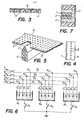
- the device illustrated in FIG. 1 comprises a support 1 in the form of a cylindrical block made of an insulating material axially traversed by a metal wire 2 made of a metal which is a good conductor of the electric current connected to one of the poles of a source of electric pulses illustrated in FIGS. 2b.
- This cylindrical block 1 is placed in a reservoir 3, containing ink, made of an electrically insulating material, having an opening 4 in which the ink contained in this reservoir 3 is retained by the cohesive force of its meniscus.
- a counter-electrode 5 is placed somewhere in the reservoir 3 at a distance from the electrode 2 and connected to the other pole of the source of electrical pulses.
- the thickness of the layer of liquid covering the electrode plays a relatively important role insofar as, with a very thin layer of the order of a few tens of / ⁇ m , a spraying of the liquid is obtained whereas with a layer of the order of a few tenths of mm, very few parasitic drops are obtained.
- the voltage applied between electrodes 2 and 5 as well as the pulse duration play a role on the size of the drops. It has been found that the necessary voltages can vary between around 500 and 4000 volts, the tests having essentially been carried out with a power supply varying between 500 and 1500 volts. App pulse duration was chosen at 5 / us.
- FIG. 7 shows a device in all points similar to that of FIG. 1 before the opening of which is placed a mask 17 having a central opening disposed opposite the electrode 2 but whose diameter is very substantially greater than that of this electrode and therefore also greater than the size of the drops.
- This mask is intended to avoid an interaction between the meniscus and the anbiant air, especially at high operating frequencies. Indeed, this interaction has the effect of producing parasitic drops and the incorporation of bubbles on the surface of the liquid.
- an insulating tape 6 in which the electrodes are located 2.
- the edge of the tape 6 has a conductive track 7.
- This tape can be inked with a ink roller (not shown) to form an ink film 8 on its surface, this film covering one side of the insulating tape 6 being in contact with the electrodes 2 and the conductive track 7 so that an electrical edge can be established at through the ink film 8, under the same conditions as in the case of FIG. 1.
- the insulating support can be formed by a fixed block 9 on one face of which the electrodes 2 are flush.
- the ink is retained in a ribbon 10 which may consist, for example, of a plastic material provided with perforations 11 filled with ink by an ink roller (not shown) applied against the underside of the ribbon 10 and the upper face of which has a metallized layer 12 and is intended to form the counter electrode.
- the metallized layer 12 can be formed from different parallel conductive tracks extending longitudinally on the surface of the strip 10.
- a circuit for addressing the electrodes 2 can for example be produced as illustrated by the diagram in FIG. 6.
- Each electrode of the same series is located at the junction of two conductors 13a, 13 b , 13 c , 13 d on the one hand and A 1 , B 1 , C l D l for the first series, A 2 , B 2 , C 2 , D 2 for the second series and A n , B n , C n , D n for the nth series.
- the electrodes 2 1a , 2 2a , 2 na are connected to the same switch 14 a
- the electrodes 2 1b , 2 2b , 2 nb are connected to the same switch 14 b
- the electrodes 2 1c , 2 2c , 2 nc are connected to the switch 14 c
- the electrodes 2 1d , 2 2d , 2 nd are connected to the switch 14 d .
- the electrodes 2 1 , 2 2 , 2 n of the same series are connected to the same switch 15 1 respectively 15 2 and 15 n by means of the conductive ink contained in n reservoirs 16 1 respectively 16 2 , 16 n .
- the reservoirs 16 1 to 16 n could correspond to the conductive tracks 12 formed on the surface of the strip 10.
- each electrode is obtained by first closing the switch 15 1 and those of the switches 14 a to 14a corresponding to the electrodes which it is desired to energize. Then the switch 15 1 and the switches 14 a to 14 d are opened and the switch 15 2 and those of the switches 14a to 14 d corresponding to the electrodes which it is desired to energize are closed.
- the distance between the electrodes should be at least 100 ⁇ m to avoid spurious interactions between electrodes. At this distance between active and non-active electrodes, the potential of the latter is much lower than the activity threshold.
- the time multiplexing of reservoirs or electrodes is easy since the duration of the pulses is of the order of 2 to 5 / us with a maximum frequency of 104 H z.
- Such an addressing circuit can be used both for an electrode array and for a line of electrodes similar to that illustrated in FIG. 5 for example.
- the device, object of the invention offers very great advantages over most existing devices. These advantages mainly arise from the fact that the drop is projected from a layer of liquid no longer requiring nozzles and making it possible to produce planar structures. For a given liquid, apart from the thickness of the liquid layer, all the parameters influencing the formation of the drops are electrical parameters. In addition, the electric current acts directly on the liquid, without the intermediary of a transducer. No parasitic resistance is put in series in the supply circuit, all the electrical resistance is concentrated in the useful zone with strong field gradient.
- the reformation of the meniscus is independent of the diameter of a nozzle and no longer depends only on the rheological properties of the liquid. It can therefore be estimated that the maximum frequency of formation of the drops can be increased compared to an on-demand inkjet device using a buzzard.
- the energy consumed by the device which is the subject of the invention is very low. If we consider for example a resistance of electrode 2 and the ink associated with it of 100,000 ohms and a supply voltage of 1000 volts, the instantaneous current is: and the instantaneous power is:
- the energy consumed during a pulse of 5 / us 5 x 10 -5 joules. This energy can be further reduced, insofar as the pulse duration could be reduced to r2 / us.
Landscapes
- Particle Formation And Scattering Control In Inkjet Printers (AREA)
- Organic Low-Molecular-Weight Compounds And Preparation Thereof (AREA)
- Electrotherapy Devices (AREA)
- Nozzles (AREA)
- Physical Or Chemical Processes And Apparatus (AREA)
Priority Applications (1)
| Application Number | Priority Date | Filing Date | Title |
|---|---|---|---|
| AT83810452T ATE25506T1 (de) | 1982-10-08 | 1983-10-05 | Vorrichtung zum ausstoss von troepfchen einer elektrisch leitenden fluessigkeit. |
Applications Claiming Priority (2)
| Application Number | Priority Date | Filing Date | Title |
|---|---|---|---|
| CH5914/82A CH649040A5 (fr) | 1982-10-08 | 1982-10-08 | Dispositif pour projeter des gouttelettes d'un liquide electriquement conducteur. |
| CH5914/82 | 1982-10-08 |
Publications (2)
| Publication Number | Publication Date |
|---|---|
| EP0106802A1 true EP0106802A1 (de) | 1984-04-25 |
| EP0106802B1 EP0106802B1 (de) | 1987-02-25 |
Family
ID=4301446
Family Applications (1)
| Application Number | Title | Priority Date | Filing Date |
|---|---|---|---|
| EP83810452A Expired EP0106802B1 (de) | 1982-10-08 | 1983-10-05 | Vorrichtung zum Ausstoss von Tröpfchen einer elektrisch leitenden Flüssigkeit |
Country Status (7)
| Country | Link |
|---|---|
| US (1) | US4575737A (de) |
| EP (1) | EP0106802B1 (de) |
| JP (1) | JPS60500010A (de) |
| AT (1) | ATE25506T1 (de) |
| CH (1) | CH649040A5 (de) |
| DE (1) | DE3369837D1 (de) |
| WO (1) | WO1984001544A1 (de) |
Cited By (3)
| Publication number | Priority date | Publication date | Assignee | Title |
|---|---|---|---|---|
| EP0363325A1 (de) * | 1988-10-05 | 1990-04-11 | Battelle Memorial Institute | Verfahren zum Antrieb von Tröpfchen einer leitfähigen Flüssigkeit |
| EP0418659A3 (en) * | 1989-09-18 | 1992-09-23 | Matsushita Electric Industrial Co., Ltd. | Ink jet recording apparatus |
| EP0694390A3 (de) * | 1994-07-29 | 1996-10-02 | Riso Kagaku Corp | Tintenstrahlgerät und leitendes Tintengemisch |
Families Citing this family (10)
| Publication number | Priority date | Publication date | Assignee | Title |
|---|---|---|---|---|
| CH659012A5 (de) * | 1982-07-20 | 1986-12-31 | Fischer Ag Georg | Verfahren und vorrichtung zum verdichten von koernigen formstoffen. |
| JPS59229345A (ja) * | 1983-05-24 | 1984-12-22 | Fuji Xerox Co Ltd | 画像記録装置 |
| US4717926A (en) * | 1985-11-09 | 1988-01-05 | Minolta Camera Kabushiki Kaisha | Electric field curtain force printer |
| CA2025538C (en) * | 1989-09-18 | 1995-03-14 | Akira Goto | Ink jet recording head, cartridge and apparatus |
| US4999650A (en) * | 1989-12-18 | 1991-03-12 | Eastman Kodak Company | Bubble jet print head having improved multiplex actuation construction |
| JPH04307252A (ja) * | 1991-04-05 | 1992-10-29 | Matsushita Electric Ind Co Ltd | インクジェットヘッド |
| ATE196447T1 (de) * | 1993-02-12 | 2000-10-15 | Tonejet Corp Pty Ltd | Verfahren und vorrichtung zur herstellung von tropfen |
| JP2783226B2 (ja) * | 1995-12-06 | 1998-08-06 | 日本電気株式会社 | インクジェット式ヘッド装置 |
| JP2907085B2 (ja) * | 1995-12-14 | 1999-06-21 | 日本電気株式会社 | インクジェット式ヘッド装置 |
| US6416678B1 (en) * | 1998-12-22 | 2002-07-09 | Xerox Corporation | Solid bi-layer structures for use with high viscosity inks in acoustic ink printing and methods of fabrication |
Citations (4)
| Publication number | Priority date | Publication date | Assignee | Title |
|---|---|---|---|---|
| US3834301A (en) * | 1971-11-17 | 1974-09-10 | Battelle Memorial Institute | Process and device for non-impact printing with liquid ink |
| GB1484368A (en) * | 1974-10-29 | 1977-09-01 | Xerox Corp | Marking method and apparatus |
| GB2031344A (en) * | 1978-10-18 | 1980-04-23 | Nippon Telegraph & Telephone | Ink recording apparatus |
| US4275290A (en) * | 1978-05-08 | 1981-06-23 | Northern Telecom Limited | Thermally activated liquid ink printing |
Family Cites Families (4)
| Publication number | Priority date | Publication date | Assignee | Title |
|---|---|---|---|---|
| JPS4945736A (en) * | 1972-09-04 | 1974-05-01 | Jukichi Sugimura | Mosaikan to denkyokukan ni kotaiatsuzetsuenban o ireta purintosochi |
| JPS5640564A (en) * | 1979-09-11 | 1981-04-16 | Ricoh Co Ltd | Ink jet recording device |
| JPS5724261A (en) * | 1980-07-21 | 1982-02-08 | Nippon Telegr & Teleph Corp <Ntt> | Head for ink recording |
| JPS5738163A (en) * | 1980-08-18 | 1982-03-02 | Matsushita Electric Ind Co Ltd | Image recording method and apparatus therefor |
-
1982
- 1982-10-08 CH CH5914/82A patent/CH649040A5/fr not_active IP Right Cessation
-
1983
- 1983-10-05 WO PCT/CH1983/000110 patent/WO1984001544A1/de not_active Ceased
- 1983-10-05 DE DE8383810452T patent/DE3369837D1/de not_active Expired
- 1983-10-05 JP JP58503086A patent/JPS60500010A/ja active Granted
- 1983-10-05 US US06/619,557 patent/US4575737A/en not_active Expired - Fee Related
- 1983-10-05 EP EP83810452A patent/EP0106802B1/de not_active Expired
- 1983-10-05 AT AT83810452T patent/ATE25506T1/de not_active IP Right Cessation
Patent Citations (4)
| Publication number | Priority date | Publication date | Assignee | Title |
|---|---|---|---|---|
| US3834301A (en) * | 1971-11-17 | 1974-09-10 | Battelle Memorial Institute | Process and device for non-impact printing with liquid ink |
| GB1484368A (en) * | 1974-10-29 | 1977-09-01 | Xerox Corp | Marking method and apparatus |
| US4275290A (en) * | 1978-05-08 | 1981-06-23 | Northern Telecom Limited | Thermally activated liquid ink printing |
| GB2031344A (en) * | 1978-10-18 | 1980-04-23 | Nippon Telegraph & Telephone | Ink recording apparatus |
Cited By (6)
| Publication number | Priority date | Publication date | Assignee | Title |
|---|---|---|---|---|
| EP0363325A1 (de) * | 1988-10-05 | 1990-04-11 | Battelle Memorial Institute | Verfahren zum Antrieb von Tröpfchen einer leitfähigen Flüssigkeit |
| US5001496A (en) * | 1988-10-05 | 1991-03-19 | Battelle Memorial Institute | Method for propelling droplets of a conductive liquid |
| CH677755A5 (de) * | 1988-10-05 | 1991-06-28 | Battelle Memorial Institute | |
| EP0418659A3 (en) * | 1989-09-18 | 1992-09-23 | Matsushita Electric Industrial Co., Ltd. | Ink jet recording apparatus |
| EP0694390A3 (de) * | 1994-07-29 | 1996-10-02 | Riso Kagaku Corp | Tintenstrahlgerät und leitendes Tintengemisch |
| US6315395B1 (en) | 1994-07-29 | 2001-11-13 | Riso Kagaku Corporation | Ink jet apparatus and conductive ink mixture |
Also Published As
| Publication number | Publication date |
|---|---|
| US4575737A (en) | 1986-03-11 |
| DE3369837D1 (en) | 1987-04-02 |
| JPS60500010A (ja) | 1985-01-10 |
| ATE25506T1 (de) | 1987-03-15 |
| CH649040A5 (fr) | 1985-04-30 |
| WO1984001544A1 (fr) | 1984-04-26 |
| EP0106802B1 (de) | 1987-02-25 |
| JPH0521744B2 (de) | 1993-03-25 |
Similar Documents
| Publication | Publication Date | Title |
|---|---|---|
| EP0106802B1 (de) | Vorrichtung zum Ausstoss von Tröpfchen einer elektrisch leitenden Flüssigkeit | |
| FR2493226A1 (fr) | Dispositif d'impression a jet selectif d'encre et tete d'impression utilisant ledit dispositif | |
| EP0521764B1 (de) | Verfahren zum Ausstossen von Flüssigkeit und Vorrichtung zum hochauflösenden Drucken an einem kontinuierlich arbeitenden Tintenstrahldrucker und Verfahrensdurchführung | |
| EP0014918B1 (de) | Vorrichtung zum Übertragen von Tintentröpfchen auf einen Aufzeichnungsträger | |
| US5455998A (en) | Method for manufacturing an ink jet head in which droplets of conductive ink are expelled | |
| US4275290A (en) | Thermally activated liquid ink printing | |
| JPH0280253A (ja) | バブル・インク・ジエツト印刷装置 | |
| JPS59207262A (ja) | プリント・ヘツド | |
| US4675694A (en) | Method and apparatus for a high density array printer using hot melt inks | |
| JPS62142655A (ja) | インクジェット・プリンタ | |
| US4021818A (en) | Liquid printing device | |
| TW514596B (en) | Glass-fiber thermal inkjet print head | |
| EP0694390B1 (de) | Tintenstrahlgerät und leitendes Tintengemisch | |
| JPS5833471A (ja) | 液体噴射記録ヘツド | |
| JP2845813B2 (ja) | 静電式インクジェット記録ヘッドの製造方法 | |
| JPS63191644A (ja) | インクジエツト記録装置 | |
| JP3063970B2 (ja) | インクジェットプリンタの噴射装置 | |
| EP0564742A2 (de) | Thermo-Tintenstrahldruckkopf mit auf Anforderung schmelzender fester Tinte | |
| JPS61162372A (ja) | インクジエツトプリンタ | |
| JP3537223B2 (ja) | インクジェット装置及び導電性インク | |
| JPS6110467A (ja) | 画像記録装置 | |
| JP2826513B2 (ja) | 静電式インクジェット記録ヘッド | |
| JPH11115208A (ja) | 画像記録装置 | |
| JPH05269988A (ja) | インクジェット記録方法及びその装置 | |
| JPH08187858A (ja) | インクジェットヘッド及びその製造方法 |
Legal Events
| Date | Code | Title | Description |
|---|---|---|---|
| PUAI | Public reference made under article 153(3) epc to a published international application that has entered the european phase |
Free format text: ORIGINAL CODE: 0009012 |
|
| AK | Designated contracting states |
Designated state(s): AT BE CH DE FR GB IT LI NL SE |
|
| 17P | Request for examination filed |
Effective date: 19840818 |
|
| GRAA | (expected) grant |
Free format text: ORIGINAL CODE: 0009210 |
|
| AK | Designated contracting states |
Kind code of ref document: B1 Designated state(s): AT BE CH DE FR GB IT LI NL SE |
|
| PG25 | Lapsed in a contracting state [announced via postgrant information from national office to epo] |
Ref country code: AT Effective date: 19870225 |
|
| REF | Corresponds to: |
Ref document number: 25506 Country of ref document: AT Date of ref document: 19870315 Kind code of ref document: T |
|
| REF | Corresponds to: |
Ref document number: 3369837 Country of ref document: DE Date of ref document: 19870402 |
|
| ITF | It: translation for a ep patent filed | ||
| PLBE | No opposition filed within time limit |
Free format text: ORIGINAL CODE: 0009261 |
|
| STAA | Information on the status of an ep patent application or granted ep patent |
Free format text: STATUS: NO OPPOSITION FILED WITHIN TIME LIMIT |
|
| 26N | No opposition filed | ||
| R20 | Corrections of a patent specification |
Effective date: 19880531 |
|
| PGFP | Annual fee paid to national office [announced via postgrant information from national office to epo] |
Ref country code: GB Payment date: 19901003 Year of fee payment: 8 |
|
| PGFP | Annual fee paid to national office [announced via postgrant information from national office to epo] |
Ref country code: SE Payment date: 19901011 Year of fee payment: 8 |
|
| PGFP | Annual fee paid to national office [announced via postgrant information from national office to epo] |
Ref country code: BE Payment date: 19901019 Year of fee payment: 8 |
|
| PGFP | Annual fee paid to national office [announced via postgrant information from national office to epo] |
Ref country code: CH Payment date: 19901030 Year of fee payment: 8 |
|
| PGFP | Annual fee paid to national office [announced via postgrant information from national office to epo] |
Ref country code: NL Payment date: 19901031 Year of fee payment: 8 |
|
| PG25 | Lapsed in a contracting state [announced via postgrant information from national office to epo] |
Ref country code: GB Effective date: 19911005 |
|
| PG25 | Lapsed in a contracting state [announced via postgrant information from national office to epo] |
Ref country code: SE Effective date: 19911006 |
|
| ITTA | It: last paid annual fee | ||
| PG25 | Lapsed in a contracting state [announced via postgrant information from national office to epo] |
Ref country code: LI Effective date: 19911031 Ref country code: CH Effective date: 19911031 Ref country code: BE Effective date: 19911031 |
|
| BERE | Be: lapsed |
Owner name: BATTELLE MEMORIAL INSTITUTE Effective date: 19911031 |
|
| PG25 | Lapsed in a contracting state [announced via postgrant information from national office to epo] |
Ref country code: NL Effective date: 19920501 |
|
| GBPC | Gb: european patent ceased through non-payment of renewal fee | ||
| NLV4 | Nl: lapsed or anulled due to non-payment of the annual fee | ||
| REG | Reference to a national code |
Ref country code: CH Ref legal event code: PL |
|
| PGFP | Annual fee paid to national office [announced via postgrant information from national office to epo] |
Ref country code: FR Payment date: 19940429 Year of fee payment: 11 |
|
| PGFP | Annual fee paid to national office [announced via postgrant information from national office to epo] |
Ref country code: DE Payment date: 19941031 Year of fee payment: 12 |
|
| EUG | Se: european patent has lapsed |
Ref document number: 83810452.9 Effective date: 19920510 |
|
| PG25 | Lapsed in a contracting state [announced via postgrant information from national office to epo] |
Ref country code: FR Effective date: 19950630 |
|
| REG | Reference to a national code |
Ref country code: FR Ref legal event code: ST |
|
| PG25 | Lapsed in a contracting state [announced via postgrant information from national office to epo] |
Ref country code: DE Effective date: 19960702 |