EP0106808A2 - Radialkolbenmaschine mit variabler Verdrängung - Google Patents
Radialkolbenmaschine mit variabler Verdrängung Download PDFInfo
- Publication number
- EP0106808A2 EP0106808A2 EP83830132A EP83830132A EP0106808A2 EP 0106808 A2 EP0106808 A2 EP 0106808A2 EP 83830132 A EP83830132 A EP 83830132A EP 83830132 A EP83830132 A EP 83830132A EP 0106808 A2 EP0106808 A2 EP 0106808A2
- Authority
- EP
- European Patent Office
- Prior art keywords
- shaft
- axis
- cam
- machine
- eccentricity
- Prior art date
- Legal status (The legal status is an assumption and is not a legal conclusion. Google has not performed a legal analysis and makes no representation as to the accuracy of the status listed.)
- Granted
Links
Images



Classifications
-
- F—MECHANICAL ENGINEERING; LIGHTING; HEATING; WEAPONS; BLASTING
- F04—POSITIVE - DISPLACEMENT MACHINES FOR LIQUIDS; PUMPS FOR LIQUIDS OR ELASTIC FLUIDS
- F04B—POSITIVE-DISPLACEMENT MACHINES FOR LIQUIDS; PUMPS
- F04B49/00—Control, e.g. of pump delivery, or pump pressure of, or safety measures for, machines, pumps, or pumping installations, not otherwise provided for, or of interest apart from, groups F04B1/00 - F04B47/00
- F04B49/12—Control, e.g. of pump delivery, or pump pressure of, or safety measures for, machines, pumps, or pumping installations, not otherwise provided for, or of interest apart from, groups F04B1/00 - F04B47/00 by varying the length of stroke of the working members
- F04B49/123—Control, e.g. of pump delivery, or pump pressure of, or safety measures for, machines, pumps, or pumping installations, not otherwise provided for, or of interest apart from, groups F04B1/00 - F04B47/00 by varying the length of stroke of the working members by changing the eccentricity of one element relative to another element
- F04B49/125—Control, e.g. of pump delivery, or pump pressure of, or safety measures for, machines, pumps, or pumping installations, not otherwise provided for, or of interest apart from, groups F04B1/00 - F04B47/00 by varying the length of stroke of the working members by changing the eccentricity of one element relative to another element by changing the eccentricity of the actuation means, e.g. cams or cranks, relative to the driving means, e.g. driving shafts
- F04B49/126—Control, e.g. of pump delivery, or pump pressure of, or safety measures for, machines, pumps, or pumping installations, not otherwise provided for, or of interest apart from, groups F04B1/00 - F04B47/00 by varying the length of stroke of the working members by changing the eccentricity of one element relative to another element by changing the eccentricity of the actuation means, e.g. cams or cranks, relative to the driving means, e.g. driving shafts with a double eccenter mechanism
-
- F—MECHANICAL ENGINEERING; LIGHTING; HEATING; WEAPONS; BLASTING
- F04—POSITIVE - DISPLACEMENT MACHINES FOR LIQUIDS; PUMPS FOR LIQUIDS OR ELASTIC FLUIDS
- F04B—POSITIVE-DISPLACEMENT MACHINES FOR LIQUIDS; PUMPS
- F04B1/00—Multi-cylinder machines or pumps characterised by number or arrangement of cylinders
- F04B1/04—Multi-cylinder machines or pumps characterised by number or arrangement of cylinders having cylinders in star- or fan-arrangement
- F04B1/06—Control
- F04B1/07—Control by varying the relative eccentricity between two members, e.g. a cam and a drive shaft
Definitions
- This invention relates to a hydrostatic machine with radial pistons.
- hydraulic machine we conceive a machine which can be driving or operating, for example a motor or a pump in which a hydraulic fluid, in general oil, exchanges pressure energy with a mechanical element.
- hydraulic machine In the word "hydrostatic machine” one must also convey the hydraulic transmissions which include a motor than a pump.
- the object of this invention is a hydrostatic machine with radial pistons having a shaft joined to an eccentric cam, with variable eccentricity, in the manner of obtaining a hydraulic machine with variable displacement which, in addition, can be self- automatically adjusted to match the variation in load conditions.
- This hydrostatic machine is configured in its general layout as a radial piston machine of the type generally used as a hydraulic motor with several radial pistons with a shaft provided with an eccentric cam and which comprises a carcass in which the cavities of the cylinders are drilled radially and an eccentric circular cam, the axis of symmetry of which is parallel to the axis of rotation of the machine, links to the shaft in the axial direction and which has eccentricity with respect to the axis of the shaft and subsequently of the machine.
- the eccentric cam is pivotally movable around the axis of a movable body interposed between shaft and eccentric cam, which is in turn pivotable around the same axis, which is parallel to the axis of the shaft and to the axis of symmetry of the cam, in such a way that in a rotation of the cam eccentric around the axis of the movable body, the center of the cam passes from a position where it is at a distance from the shaft in which the resulting eccentricity is the difference of the two eccentric distances, to another diametrically opposite position where the two eccentricities overlap between them.
- the distance from the center of the cam to the shaft axis measures the effective eccentricity that this cam has in relation to the shaft.
- This movable body is in another engaged with the shaft and the eccentric cam respectively with screw couplings, at least one of which is with reversible screw, these screws having cylindrical helix spinning with different geometrical characteristics; as well as a relative rotation between the shaft and the eccentric cam corresponds to a displacement of the movable body along its axis.
- the axial displacement of this movable body is preferably contrasted by suitable elastic means engaged respectively between the movable body and the eccentric cam, so that there will be a self-adjusting system by the equilibrium between the torsional moment which causes a relative rotation between the cam and the shaft, and the elastic reaction of these elastic means.
- the machine of the invention has an offset between the axis of the shaft and the axis of the movable body.
- this last distance and this offset may be different from each other, and this is part of the scope of this invention, to facilitate description and as a preferred embodiment it is assumed below that this distance and this offset are of the same length.
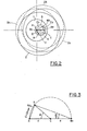
- the machine of the invention generally comprises: a shaft 1 with axis A, an eccentric disc 2 or cam with axis of symmetry B and a movable body 3 with axis of rotation C.
- the movable body 3 is coupled to the shaft 1 and the cam 2 with screw coupling 4 and 5 respectively.
- the screws 4 and 5, according to the invention, must be of different threads and at least one must be reversible.
- the thread 4 is represented as a coupling with axial slots, as well as the shaft 1 and the movable body 3 are vinculated with axial sliding, sqns reciprocal rotation.
- the shaft 1 and the cam 2 are vinculated not to move axially relative to each other, by mechanical construction, but they can roll one compared to each other.
- At least one elastic element axially tires the movable body 3 towards an axial direction
- the axis C of the movable body 3 is offset from the axis A of the shaft by a distance d
- the axis B of the cam 2 is placed at the same distance d from the axis C of the movable body 3.
- cam 2 is coupled on its periphery with radial pistons (not shown) in turn enga managed in convertional means with a carcass (not illustrated).
- the fixed element of the machine can be the carcass, in this case the shaft-cam assembly rolls around the axis of the shaft, or else the carcass is the rolling element and the assembly camshaft is fixed.
- the shaft-cam assembly is not rigid, but the cam 2 can gain different positions by varying its eccentricity while the shaft 1 can be fixed.
- the axis of symmetry B of the cam 2 can move along the circle F, having as its center the axis C of the movable body 3.
- the moment of the torsion which causes the cam to roll derives from the force explained by the pressure in the pistons multiplied by the eccentricity E gained by the cam which serves as a crank arm. (This condition does not naturally occur at zero eccentricity).
- the eccentricity E that means the length of this crank arm, is a sinusoidal function of the angle of rotation ⁇ of the eccentric cam 2 around the axis C of the moving body 3.
- the value of the torsional moment also has a sinusoidal shape, and consequently the axial thrust of the moving body 3 will also have - if a sinusoidal shape due to the torsional moment.
- this moment of torsion is none other than the motor moment which manifests itself in the machine as a consequence of the value of the pressure which is established in the cylinders, motor moment which it takes to overcome the moment resisting it applied.
- the curves P 1 , P2 ; ?? P n shown in the 4 th picture (f ig. 4), show on the ordinate the sinusoidal shape of the axial thrusts of values H, caused by a moment of Torion produced by the action of different pressures in the cylinders.
- Each curve represents a constant pressure at the variation of the angle (on the abscissa) and therefore of the eccentricity.
- a family of curves is thus obtained, each of which is at constant pressure and these curves are arranged with increasing pressure upwards.
- the line m shown in the 4 th image (fig. 4), which starts from the origin, represents the characteristic, for example linear, of the elastic means employed which provides a reaction Z (on the coordinate).
- This line has an inclination which depends on the rigidity of the elastic means adopted.
- the points Q of in are thus shown intersection between this line and the curves of the axial thrust H due to the moment of torsion.
- intersection points represent the equilibrium point between the pressure on the cam 2 (torsional moment) and the reaction of the elastic means depending on the rotation of the cam 2.
- the movable body 3 as already said, is characterized in that it has two screw threads with different geometrical characteristics on two different parts of its surface.
- It may consist of a cylindrical element which has two thickened aylindrical ends on the surface of which these threads are executed with screw threads engaging with the shaft and with the cam, as shown in the first image. (fig. 1).
- Another embodiment consists in making the movable body in the form of a sleeve and the threads are executed one outside the sleeve and the other inside the hole of the sleeve as illustrated with the 8 in the 5th picture (f ig .5).
- Another embodiment provides a body generally with cylindrical mushroom in which an external thread is executed on the external surface of the cylinder which constitutes the cap of the mushroom and another thread on the cylindrical tail of this mushroom.
- This embodiment is illustrated with 9 in the 6 th image and with 1 0 in the 7 th image.
- These elastic means can be cylindrical springs, volute springs, cutting or undercut springs, which are expediently requested from suitable appendages applied to the movable body and the same springs can be rented either indoors or outdoors. outside of the shaft or cam.
- a particularly interesting embodiment provides for a spring the springs, which are heavy and bulky, with a servo-mechanism amplifying the characteristic of a small calibrated spring, leads to control, depending on the deformation of the spring, the value of the pressure oil which acts on a piston which contrasts the axial movement of the movable body and therefore the rotation of the exentric cam.
- a subsequent embodiment provides for exhausting the elastic qualities of a compressed gas, for example by putting in fluid communication a hydraulic accumulator with a variable volume cavity defined by a piston which moves in a cylinder, the piston and the cylinder being respectively joined to the movable body and the shaft or to the movable body and the cam.
- the hydraulic accumulator which has its very contained dimentiors can be installed outside the machine and can find a favorable position very close to it.
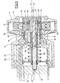
- This eccentric cam 15 is movably pinched to the shaft 12 being supported in rotation for example through rolling bearings 16 by a cylindrical head 17, preferably coric, projecting from the shaft 12, with axis C eccentric with respect to axis A of tree 12.
- the eccentric cam 15 has a cylindrical eyelets 18, preferably conical, complementary to the head 17 of the shaft 12, with its axis coinciding with the axis C of disaxation.
- To the cam 15 is secured, through bolts 19, an enlarged head 20 of a reversible screw 21 having its axis coincide with the axis C of offset of the recess 18 and therefore of the cam 15, which is arranged so as to result inside this recesses 18, the other end 23 of this screw 21 being rotatably supported in a seat 22 executed in the shaft 12.
- the reversible screw 21 is engaged in the hole 24 of a cylindrical sleeve 8 which constitutes the movable body, this sleeve 8 having on its outer surface, rectilinear slots 25 or very long pitch propeller.
- the slots 25 of the sleeve 8 are engaged in the corresponding slots 26 of an axial hole executed in the shaft 12, the axis of this hole being coincident with the axis C of the screw and therefore eccentric with respect to the 'axis A of the shaft 12, as well as this hole results in an axis with the eccentric head 17 of the shaft 12 which is fully engaged.
- the hole in the shaft 12 opens at the other end into a recess 27 with an enlarged diameter in which slides, with fluid resistance, a piston disc 28 which is integral, through an appendage 29, or sleeve 8.
- This piston disc 29 is another Y in the center, held, of the other end 23 of the screw 25 which in this case is executed with a smooth tail.
- this recess 27 with an enlarged diameter is another lodged spring 30 in compression which acts between this disc of pistons 28 and the shaft 12.
- the eccentric cam 15 rolls at a certain angle and the sleeve 8 is returned by the screw 21 integral with the eccentric 15, in a d 'being guided to slide in the annular gap between the screw 21 and the head 17 of the shaft, driving the disc of the piston 28 which, other than pressing the spring 30, also reduces the volume of the widened recess 27.
- This widened recess 27 is placed in fluid communication, preferably with a hydraulic accumulator (not shown) from which the elastic compression of the gas it contains is used.
- the pressure rise in the accumulator as a function of the reduction in volume of this recess 27 is such that the accumulator operates in parallel with the spring 30.
- the resulting cylinder chamber on the other side of the piston disc 28, when it moves in the enlarged reel 27, can be used to modify the characteristic of the spring by supplying pressure-controlled oil to this chamber.
- An annular distributor 31 is attached to the shaft 12 and is movable in relation to it. Since the disc 15 moves angularly with respect to the shaft 12, the distributor also must perform the same angular rotation around the shaft 12.
- the eccentric cam 15 has a button 32 tilting laterally, which engages in a radial slot 33 executed in the distributor 31, as it carries it in rotation despite the eccentricity existing between the eccentric cam 15 and the axis A of the tree 12.
- FIG. 6 an embodiment of the machine according to this invention is described which functions differently as a pump or as a motor with a fixed carcass 34 and with the rolling shaft 35.
- a inside the carcass 34 are defined recesses 36 of the cylinders in which slide back and forth pistons 37 radially movable.
- the pistons 37 receive the thrust in the cylinders of a hydraulic fluid under pressure ⁇ and transmit it through suitable hydrostatic pads to the eccentric cam 38 by placing it in rotation.
- the eccentric cam 37 is pivoted on the shaft 35, being rotatably supported for example through a mechanical sliding coupling, on a cylindrical or slightly conical head 39, projecting from the shaft 35 and with axis C eccentric by relative to the axis A of the shaft 35.
- the disc 35 has a complementary recess 40, cylindrical or slightly conical, with an axis coincident with the axis of misalignment and a central protuberance 41 inside this recess 40 in which a threaded hole 42 with reversible screw is made having the same offset axis C,
- the tree 35 with sound. inside has an axial cylindrical recess 46, the axis of this recess being coincident with the axis C of the screw 43, and therefore offset from the axis A of the shaft 35.
- the interior surface of the evidge 46 has slots 47 in which the slots 45 of this appendage 44 with mushrooms are engaged.
- This recess 46 opens into the cylindrical projecting head 39.
- the mushroom disc 44 in turn is integral with a peripheral mantle 48 thus defining a recess 51 of cylinder in which is engaged sliding and fluid holding a counter cylinder 49 in turn rented in the hose 40 of the eccentric cam 38.
- the. eccentric cam 38 rolls at a certain angle, while the shaft 35 is driven by the load applied to it and the screw 43 is returned to the hole 40 of the eccentric 38, driving the mushroom disc 44 and reducing the volume of the cylinder recess 51 and compress a spring 50 disposed inside this recesses 51.
- This cylinder recess 51 is arranged in fluid communication with a hydraulic accumulator (not shown) from which the elastic properties of the gas are used and which, however, operates in parallel with the spring.
- the execution form presented provides for a planar rolling distributor 52 and yet it is necessary to rotate the planar distributor 52 in synchronism with the eccentric cam 38, while this cam 38 rolls with the shaft 35 holding in place only during the rotation of the 'shaft, this cam performs small angular displacements relative to the shaft.
- the eccentric cam 38 has a cylindrical projection 53 in axis with the screw 43, this projection 53 being housed in a cylindrical sleeve 54 suitably supported in the carcass 34 and in axis with the axis A of the shaft 35.
- the housing hole of the projection of the sleeve 54 has on the contrary. its axis moves in the same direction as the axis C of the screw 43, as are the angular displacements of the eccentric cam 38 during rotation.
- a radial slot 55 In the end part of the cylindrical projection 53 is executed a radial slot 55 in which a sliding prismatic shoe 53 is engaged, executed in the end part of a small shaft 57.
- This small shaft in turn drives the rolling plane distributor disc 52.
- FIG. 7 discloses an embodiment of the machine according to this invention, as Working motor shaft and fixed carcass wheel mounted within a wheel of a vehicle.
- a rolling carcass 58 coaxial with the axis A of the shaft 59, and therefore of the machine, there are defined recesses 60 of cylinders in which flow in aisle and return of radially movable pistons 61.
- This eccentric cam 62 is pivotally engaged with the shaft 59, being supported in rotation, for example with a mechanical sliding coupling by means of a counter-shaft 65 integral with the disc and which rolls in a hole 66 executed in the shaft having the axis C eccentric with respect to the axis A of the shaft.
- the reversible screw 67 is engaged in a threaded hole 68 executed in the central tail 69 of a mushroom cap # on 70 which constitutes the movable body 10.
- This cap 70 present on the edge of the threads 71 straight or with a long pitch propeller, which engages in axial sliding in a cylindrical recess 72 executed in an enlarged part 73 of the shaft, the axis of this recess 72 being coincide with the axis C of the screw and therefore off-center with respect to the axis A of the shaft.
- the anterior surface of this recess of the shaft has the threads 74 in which the threads 71 of the hood 70 with mushrooms are engaged.
- the peripheral mantle 74 of the cap delimits a recess 76 of the cylinder in which a counter-cylinder 77 is engaged in sliding and fluid-holding 77 and in turn mounted on a seat 78 executed on the counter-shaft 65 in axis with the screw 67 .
- This cylinder recess is full of oil that in this way is pressurized and prevents the rotation of the screw.
- the increase in oil pressure is transmitted, through a hole 79 made in the tail, also in the recess of the hole 68 with screw thread and therefore acts on a small piston 80 which slides with fluid holding in a axial hole 81 executed centrally- ment to the screw 67 and which passes inside the countershaft 65 and the eccentric cam 62.
- the small piston 80 is contrasted by a calibrated and calibrated spring 82 rented inside the axial hole 81. Under the action of the oil pressure, the small piston 80 compresses the spring 28 so that the pressure which prevails in the cylinder recess is essentially a linear function of the deformation of the spring.
- the small piston 80 has inside a recess at the bottom of which is made a discharge hole 83 which has a conical seat.
- This conical seat as a result of the reaction of the calibrated spring on the small piston, is held normally closed by a small cone head 84, supported at one end of a bar 85, the other end of which controls a high valve.
- pressure 86 normally closed, outside placed in communication with a source of oil under pressure.
- the recall of the screw corresponds to an increase in the pressure in the cylinder recess and therefore a displacement of the small piston in the sems to compress the calibrated spring 82.
- the capuohon 70 can thus be attracted by the screw until the pressure inside the cylindrical recess balances the action of the spring on the small piston, with a contemporary closure, of the conical seat.
- a reduction of the action of the screw on the cap corresponds to an instantaneous drop in pressure in the cylinder recess and comes out by acting against the small piston, by means of the bar, opens the valve 86 of high pressure, consenting to oil to enter the cylinder recess, until the spring action is balanced.
- the device constituted by the small piston, by the bar and by the high pressure valve functions in the manner of a servomechanism amplifying the elastic characteristic of the calibrated spring.
- the axial hole 81 serves also to oil discharge channel that supplied to the cylinders and a small hole 88 practiced into the axial hole can drain drawing of oil which fills the carcass during operation.
- the carcass present at its periphery a circular flange 89 provided with holes 90 to allow mounting to the tire of a vehicle wheel.
- the shaft present on its outside a thread 91 thus being able to be supported in a keeper 92 for mounting to the suspensions of a vehicle, by means of bolts which pass through the holes 93.
Landscapes
- Engineering & Computer Science (AREA)
- Mechanical Engineering (AREA)
- General Engineering & Computer Science (AREA)
- Reciprocating Pumps (AREA)
- Transmission Devices (AREA)
Applications Claiming Priority (2)
| Application Number | Priority Date | Filing Date | Title |
|---|---|---|---|
| IT48727/82A IT1189306B (it) | 1982-06-30 | 1982-06-30 | Macchina idrostatica a pistoni radiali e cilindrata variabile |
| IT4872782 | 1982-06-30 |
Publications (3)
| Publication Number | Publication Date |
|---|---|
| EP0106808A2 true EP0106808A2 (de) | 1984-04-25 |
| EP0106808A3 EP0106808A3 (en) | 1985-01-09 |
| EP0106808B1 EP0106808B1 (de) | 1989-11-08 |
Family
ID=11268278
Family Applications (1)
| Application Number | Title | Priority Date | Filing Date |
|---|---|---|---|
| EP83830132A Expired EP0106808B1 (de) | 1982-06-30 | 1983-06-28 | Radialkolbenmaschine mit variabler Verdrängung |
Country Status (3)
| Country | Link |
|---|---|
| EP (1) | EP0106808B1 (de) |
| DE (1) | DE3380826D1 (de) |
| IT (1) | IT1189306B (de) |
Cited By (2)
| Publication number | Priority date | Publication date | Assignee | Title |
|---|---|---|---|---|
| EP0191535A1 (de) * | 1985-02-13 | 1986-08-20 | B.V. Koninklijke Maatschappij "De Schelde" | Antriebssystem für Benutzer an Bord eines Schiffes |
| EP0908626A1 (de) * | 1997-10-06 | 1999-04-14 | Sabi Pompe e Impianti S.r.l. | Steuerungssystem verwendbar in einer Dosierpumpe |
Family Cites Families (3)
| Publication number | Priority date | Publication date | Assignee | Title |
|---|---|---|---|---|
| GB538230A (en) * | 1940-02-02 | 1941-07-25 | Charles Hyland | Improvements in or relating to eccentrics |
| GB577287A (en) * | 1943-06-04 | 1946-05-13 | George Walstan Drury | Improvements in reciprocating pumps |
| FR1120102A (fr) * | 1955-01-14 | 1956-07-02 | Dispositif de commande d'excentricité |
-
1982
- 1982-06-30 IT IT48727/82A patent/IT1189306B/it active
-
1983
- 1983-06-28 DE DE8383830132T patent/DE3380826D1/de not_active Expired
- 1983-06-28 EP EP83830132A patent/EP0106808B1/de not_active Expired
Cited By (2)
| Publication number | Priority date | Publication date | Assignee | Title |
|---|---|---|---|---|
| EP0191535A1 (de) * | 1985-02-13 | 1986-08-20 | B.V. Koninklijke Maatschappij "De Schelde" | Antriebssystem für Benutzer an Bord eines Schiffes |
| EP0908626A1 (de) * | 1997-10-06 | 1999-04-14 | Sabi Pompe e Impianti S.r.l. | Steuerungssystem verwendbar in einer Dosierpumpe |
Also Published As
| Publication number | Publication date |
|---|---|
| IT1189306B (it) | 1988-02-04 |
| IT8248727A1 (it) | 1983-12-30 |
| IT8248727A0 (it) | 1982-06-30 |
| DE3380826D1 (en) | 1989-12-14 |
| EP0106808A3 (en) | 1985-01-09 |
| EP0106808B1 (de) | 1989-11-08 |
Similar Documents
| Publication | Publication Date | Title |
|---|---|---|
| FR2515383A1 (fr) | Dispositif de reglage continu de l'amplitude de vibration d'elements excentriques | |
| FR2673685A1 (fr) | Compresseur du type rotatif pour climatisation ou refrigeration. | |
| JPS6123390B2 (de) | ||
| FR2654788A1 (fr) | Variateur de vitesse. | |
| FR2479351A1 (fr) | Convertisseur | |
| FR2749045A1 (fr) | Compresseur, notamment pour des systemes de climatisation dans des vehicules | |
| CA1307163C (fr) | Machine rotative a pistons et a barillet avec rotule de centrage fixe | |
| JPS59150986A (ja) | 回転ピストン式のピストンポンプ | |
| EP1602826A1 (de) | Pumpenantrieb | |
| EP0106808B1 (de) | Radialkolbenmaschine mit variabler Verdrängung | |
| FR2551144A1 (fr) | Commande de compensation de baisse de vitesse d'une pompe a cylindree variable reliee a un moteur | |
| FR2559846A1 (fr) | Machine hydraulique de type rotatif | |
| US11560907B2 (en) | Device for amplifying a force, and related systems and methods | |
| JP3569759B2 (ja) | 可変容量型斜板式液圧機械 | |
| FR2925622A1 (fr) | Machine hydrostatique volumetrique a cylindree reglable en continu | |
| FR2668553A1 (fr) | Machine tournante a butee axiale auto-eclipsable a membrane flexible soumise a la pression d'un fluide. | |
| FR2785646A1 (fr) | Compresseur a dispositif d'ajustement du jeu axial de l'arbre | |
| US3527145A (en) | Axial piston unit usable as liquid pump and/or motor | |
| EP0292062B1 (de) | Bremse-Kupplungsgruppe für mechanisches Pressen | |
| FR2547010A1 (fr) | Mecanisme de transmission et puissance | |
| BE1015545A3 (fr) | Systeme de transformation d'energie a appareil volumetrique. | |
| EP0481046B1 (de) | Radialzylindermotoren und -pumpen | |
| EP2825785B1 (de) | Hydraulischer verstellmotor, insbesondere für ein kraftfahrzeug | |
| JPH0126424B2 (de) | ||
| JPH03112582U (de) |
Legal Events
| Date | Code | Title | Description |
|---|---|---|---|
| PUAI | Public reference made under article 153(3) epc to a published international application that has entered the european phase |
Free format text: ORIGINAL CODE: 0009012 |
|
| AK | Designated contracting states |
Designated state(s): CH DE FR GB LI |
|
| PUAL | Search report despatched |
Free format text: ORIGINAL CODE: 0009013 |
|
| AK | Designated contracting states |
Designated state(s): CH DE FR GB LI |
|
| 17P | Request for examination filed |
Effective date: 19850624 |
|
| GRAA | (expected) grant |
Free format text: ORIGINAL CODE: 0009210 |
|
| AK | Designated contracting states |
Kind code of ref document: B1 Designated state(s): CH DE FR GB LI |
|
| REF | Corresponds to: |
Ref document number: 3380826 Country of ref document: DE Date of ref document: 19891214 |
|
| GBV | Gb: ep patent (uk) treated as always having been void in accordance with gb section 77(7)/1977 [no translation filed] | ||
| PLBE | No opposition filed within time limit |
Free format text: ORIGINAL CODE: 0009261 |
|
| STAA | Information on the status of an ep patent application or granted ep patent |
Free format text: STATUS: NO OPPOSITION FILED WITHIN TIME LIMIT |
|
| GBRI | Gb: ep (uk) patent reinstated (gb rule 110(3)a/1987) | ||
| GBT | Gb: translation of ep patent filed (gb section 77(6)(a)/1977) | ||
| 26N | No opposition filed | ||
| PGFP | Annual fee paid to national office [announced via postgrant information from national office to epo] |
Ref country code: CH Payment date: 19920629 Year of fee payment: 10 |
|
| PG25 | Lapsed in a contracting state [announced via postgrant information from national office to epo] |
Ref country code: LI Effective date: 19930630 Ref country code: CH Effective date: 19930630 |
|
| REG | Reference to a national code |
Ref country code: CH Ref legal event code: PL |
|
| PGFP | Annual fee paid to national office [announced via postgrant information from national office to epo] |
Ref country code: DE Payment date: 19940615 Year of fee payment: 12 |
|
| PGFP | Annual fee paid to national office [announced via postgrant information from national office to epo] |
Ref country code: GB Payment date: 19940627 Year of fee payment: 12 |
|
| PGFP | Annual fee paid to national office [announced via postgrant information from national office to epo] |
Ref country code: FR Payment date: 19941115 Year of fee payment: 12 |
|
| PG25 | Lapsed in a contracting state [announced via postgrant information from national office to epo] |
Ref country code: GB Effective date: 19950628 |
|
| GBPC | Gb: european patent ceased through non-payment of renewal fee |
Effective date: 19950628 |
|
| PG25 | Lapsed in a contracting state [announced via postgrant information from national office to epo] |
Ref country code: FR Effective date: 19960229 |
|
| PG25 | Lapsed in a contracting state [announced via postgrant information from national office to epo] |
Ref country code: DE Effective date: 19960301 |
|
| REG | Reference to a national code |
Ref country code: FR Ref legal event code: ST |