EP0106808A2 - Machine hydrostatique à pistons radiaux et cylindrée variable - Google Patents
Machine hydrostatique à pistons radiaux et cylindrée variable Download PDFInfo
- Publication number
- EP0106808A2 EP0106808A2 EP83830132A EP83830132A EP0106808A2 EP 0106808 A2 EP0106808 A2 EP 0106808A2 EP 83830132 A EP83830132 A EP 83830132A EP 83830132 A EP83830132 A EP 83830132A EP 0106808 A2 EP0106808 A2 EP 0106808A2
- Authority
- EP
- European Patent Office
- Prior art keywords
- shaft
- axis
- cam
- machine
- eccentricity
- Prior art date
- Legal status (The legal status is an assumption and is not a legal conclusion. Google has not performed a legal analysis and makes no representation as to the accuracy of the status listed.)
- Granted
Links
Images



Classifications
-
- F—MECHANICAL ENGINEERING; LIGHTING; HEATING; WEAPONS; BLASTING
- F04—POSITIVE - DISPLACEMENT MACHINES FOR LIQUIDS; PUMPS FOR LIQUIDS OR ELASTIC FLUIDS
- F04B—POSITIVE-DISPLACEMENT MACHINES FOR LIQUIDS; PUMPS
- F04B49/00—Control, e.g. of pump delivery, or pump pressure of, or safety measures for, machines, pumps, or pumping installations, not otherwise provided for, or of interest apart from, groups F04B1/00 - F04B47/00
- F04B49/12—Control, e.g. of pump delivery, or pump pressure of, or safety measures for, machines, pumps, or pumping installations, not otherwise provided for, or of interest apart from, groups F04B1/00 - F04B47/00 by varying the length of stroke of the working members
- F04B49/123—Control, e.g. of pump delivery, or pump pressure of, or safety measures for, machines, pumps, or pumping installations, not otherwise provided for, or of interest apart from, groups F04B1/00 - F04B47/00 by varying the length of stroke of the working members by changing the eccentricity of one element relative to another element
- F04B49/125—Control, e.g. of pump delivery, or pump pressure of, or safety measures for, machines, pumps, or pumping installations, not otherwise provided for, or of interest apart from, groups F04B1/00 - F04B47/00 by varying the length of stroke of the working members by changing the eccentricity of one element relative to another element by changing the eccentricity of the actuation means, e.g. cams or cranks, relative to the driving means, e.g. driving shafts
- F04B49/126—Control, e.g. of pump delivery, or pump pressure of, or safety measures for, machines, pumps, or pumping installations, not otherwise provided for, or of interest apart from, groups F04B1/00 - F04B47/00 by varying the length of stroke of the working members by changing the eccentricity of one element relative to another element by changing the eccentricity of the actuation means, e.g. cams or cranks, relative to the driving means, e.g. driving shafts with a double eccenter mechanism
-
- F—MECHANICAL ENGINEERING; LIGHTING; HEATING; WEAPONS; BLASTING
- F04—POSITIVE - DISPLACEMENT MACHINES FOR LIQUIDS; PUMPS FOR LIQUIDS OR ELASTIC FLUIDS
- F04B—POSITIVE-DISPLACEMENT MACHINES FOR LIQUIDS; PUMPS
- F04B1/00—Multi-cylinder machines or pumps characterised by number or arrangement of cylinders
- F04B1/04—Multi-cylinder machines or pumps characterised by number or arrangement of cylinders having cylinders in star- or fan-arrangement
- F04B1/06—Control
- F04B1/07—Control by varying the relative eccentricity between two members, e.g. a cam and a drive shaft
Definitions
- This invention relates to a hydrostatic machine with radial pistons.
- hydraulic machine we conceive a machine which can be driving or operating, for example a motor or a pump in which a hydraulic fluid, in general oil, exchanges pressure energy with a mechanical element.
- hydraulic machine In the word "hydrostatic machine” one must also convey the hydraulic transmissions which include a motor than a pump.
- the object of this invention is a hydrostatic machine with radial pistons having a shaft joined to an eccentric cam, with variable eccentricity, in the manner of obtaining a hydraulic machine with variable displacement which, in addition, can be self- automatically adjusted to match the variation in load conditions.
- This hydrostatic machine is configured in its general layout as a radial piston machine of the type generally used as a hydraulic motor with several radial pistons with a shaft provided with an eccentric cam and which comprises a carcass in which the cavities of the cylinders are drilled radially and an eccentric circular cam, the axis of symmetry of which is parallel to the axis of rotation of the machine, links to the shaft in the axial direction and which has eccentricity with respect to the axis of the shaft and subsequently of the machine.
- the eccentric cam is pivotally movable around the axis of a movable body interposed between shaft and eccentric cam, which is in turn pivotable around the same axis, which is parallel to the axis of the shaft and to the axis of symmetry of the cam, in such a way that in a rotation of the cam eccentric around the axis of the movable body, the center of the cam passes from a position where it is at a distance from the shaft in which the resulting eccentricity is the difference of the two eccentric distances, to another diametrically opposite position where the two eccentricities overlap between them.
- the distance from the center of the cam to the shaft axis measures the effective eccentricity that this cam has in relation to the shaft.
- This movable body is in another engaged with the shaft and the eccentric cam respectively with screw couplings, at least one of which is with reversible screw, these screws having cylindrical helix spinning with different geometrical characteristics; as well as a relative rotation between the shaft and the eccentric cam corresponds to a displacement of the movable body along its axis.
- the axial displacement of this movable body is preferably contrasted by suitable elastic means engaged respectively between the movable body and the eccentric cam, so that there will be a self-adjusting system by the equilibrium between the torsional moment which causes a relative rotation between the cam and the shaft, and the elastic reaction of these elastic means.
- the machine of the invention has an offset between the axis of the shaft and the axis of the movable body.
- this last distance and this offset may be different from each other, and this is part of the scope of this invention, to facilitate description and as a preferred embodiment it is assumed below that this distance and this offset are of the same length.
- the machine of the invention generally comprises: a shaft 1 with axis A, an eccentric disc 2 or cam with axis of symmetry B and a movable body 3 with axis of rotation C.
- the movable body 3 is coupled to the shaft 1 and the cam 2 with screw coupling 4 and 5 respectively.
- the screws 4 and 5, according to the invention, must be of different threads and at least one must be reversible.
- the thread 4 is represented as a coupling with axial slots, as well as the shaft 1 and the movable body 3 are vinculated with axial sliding, sqns reciprocal rotation.
- the shaft 1 and the cam 2 are vinculated not to move axially relative to each other, by mechanical construction, but they can roll one compared to each other.
- At least one elastic element axially tires the movable body 3 towards an axial direction
- the axis C of the movable body 3 is offset from the axis A of the shaft by a distance d
- the axis B of the cam 2 is placed at the same distance d from the axis C of the movable body 3.
- cam 2 is coupled on its periphery with radial pistons (not shown) in turn enga managed in convertional means with a carcass (not illustrated).
- the fixed element of the machine can be the carcass, in this case the shaft-cam assembly rolls around the axis of the shaft, or else the carcass is the rolling element and the assembly camshaft is fixed.
- the shaft-cam assembly is not rigid, but the cam 2 can gain different positions by varying its eccentricity while the shaft 1 can be fixed.
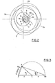
- the axis of symmetry B of the cam 2 can move along the circle F, having as its center the axis C of the movable body 3.
- the moment of the torsion which causes the cam to roll derives from the force explained by the pressure in the pistons multiplied by the eccentricity E gained by the cam which serves as a crank arm. (This condition does not naturally occur at zero eccentricity).
- the eccentricity E that means the length of this crank arm, is a sinusoidal function of the angle of rotation ⁇ of the eccentric cam 2 around the axis C of the moving body 3.
- the value of the torsional moment also has a sinusoidal shape, and consequently the axial thrust of the moving body 3 will also have - if a sinusoidal shape due to the torsional moment.
- this moment of torsion is none other than the motor moment which manifests itself in the machine as a consequence of the value of the pressure which is established in the cylinders, motor moment which it takes to overcome the moment resisting it applied.
- the curves P 1 , P2 ; ?? P n shown in the 4 th picture (f ig. 4), show on the ordinate the sinusoidal shape of the axial thrusts of values H, caused by a moment of Torion produced by the action of different pressures in the cylinders.
- Each curve represents a constant pressure at the variation of the angle (on the abscissa) and therefore of the eccentricity.
- a family of curves is thus obtained, each of which is at constant pressure and these curves are arranged with increasing pressure upwards.
- the line m shown in the 4 th image (fig. 4), which starts from the origin, represents the characteristic, for example linear, of the elastic means employed which provides a reaction Z (on the coordinate).
- This line has an inclination which depends on the rigidity of the elastic means adopted.
- the points Q of in are thus shown intersection between this line and the curves of the axial thrust H due to the moment of torsion.
- intersection points represent the equilibrium point between the pressure on the cam 2 (torsional moment) and the reaction of the elastic means depending on the rotation of the cam 2.
- the movable body 3 as already said, is characterized in that it has two screw threads with different geometrical characteristics on two different parts of its surface.
- It may consist of a cylindrical element which has two thickened aylindrical ends on the surface of which these threads are executed with screw threads engaging with the shaft and with the cam, as shown in the first image. (fig. 1).
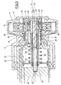
- Another embodiment consists in making the movable body in the form of a sleeve and the threads are executed one outside the sleeve and the other inside the hole of the sleeve as illustrated with the 8 in the 5th picture (f ig .5).
- Another embodiment provides a body generally with cylindrical mushroom in which an external thread is executed on the external surface of the cylinder which constitutes the cap of the mushroom and another thread on the cylindrical tail of this mushroom.
- This embodiment is illustrated with 9 in the 6 th image and with 1 0 in the 7 th image.
- These elastic means can be cylindrical springs, volute springs, cutting or undercut springs, which are expediently requested from suitable appendages applied to the movable body and the same springs can be rented either indoors or outdoors. outside of the shaft or cam.
- a particularly interesting embodiment provides for a spring the springs, which are heavy and bulky, with a servo-mechanism amplifying the characteristic of a small calibrated spring, leads to control, depending on the deformation of the spring, the value of the pressure oil which acts on a piston which contrasts the axial movement of the movable body and therefore the rotation of the exentric cam.
- a subsequent embodiment provides for exhausting the elastic qualities of a compressed gas, for example by putting in fluid communication a hydraulic accumulator with a variable volume cavity defined by a piston which moves in a cylinder, the piston and the cylinder being respectively joined to the movable body and the shaft or to the movable body and the cam.
- the hydraulic accumulator which has its very contained dimentiors can be installed outside the machine and can find a favorable position very close to it.
- This eccentric cam 15 is movably pinched to the shaft 12 being supported in rotation for example through rolling bearings 16 by a cylindrical head 17, preferably coric, projecting from the shaft 12, with axis C eccentric with respect to axis A of tree 12.
- the eccentric cam 15 has a cylindrical eyelets 18, preferably conical, complementary to the head 17 of the shaft 12, with its axis coinciding with the axis C of disaxation.
- To the cam 15 is secured, through bolts 19, an enlarged head 20 of a reversible screw 21 having its axis coincide with the axis C of offset of the recess 18 and therefore of the cam 15, which is arranged so as to result inside this recesses 18, the other end 23 of this screw 21 being rotatably supported in a seat 22 executed in the shaft 12.
- the reversible screw 21 is engaged in the hole 24 of a cylindrical sleeve 8 which constitutes the movable body, this sleeve 8 having on its outer surface, rectilinear slots 25 or very long pitch propeller.
- the slots 25 of the sleeve 8 are engaged in the corresponding slots 26 of an axial hole executed in the shaft 12, the axis of this hole being coincident with the axis C of the screw and therefore eccentric with respect to the 'axis A of the shaft 12, as well as this hole results in an axis with the eccentric head 17 of the shaft 12 which is fully engaged.
- the hole in the shaft 12 opens at the other end into a recess 27 with an enlarged diameter in which slides, with fluid resistance, a piston disc 28 which is integral, through an appendage 29, or sleeve 8.
- This piston disc 29 is another Y in the center, held, of the other end 23 of the screw 25 which in this case is executed with a smooth tail.
- this recess 27 with an enlarged diameter is another lodged spring 30 in compression which acts between this disc of pistons 28 and the shaft 12.
- the eccentric cam 15 rolls at a certain angle and the sleeve 8 is returned by the screw 21 integral with the eccentric 15, in a d 'being guided to slide in the annular gap between the screw 21 and the head 17 of the shaft, driving the disc of the piston 28 which, other than pressing the spring 30, also reduces the volume of the widened recess 27.
- This widened recess 27 is placed in fluid communication, preferably with a hydraulic accumulator (not shown) from which the elastic compression of the gas it contains is used.
- the pressure rise in the accumulator as a function of the reduction in volume of this recess 27 is such that the accumulator operates in parallel with the spring 30.
- the resulting cylinder chamber on the other side of the piston disc 28, when it moves in the enlarged reel 27, can be used to modify the characteristic of the spring by supplying pressure-controlled oil to this chamber.
- An annular distributor 31 is attached to the shaft 12 and is movable in relation to it. Since the disc 15 moves angularly with respect to the shaft 12, the distributor also must perform the same angular rotation around the shaft 12.
- the eccentric cam 15 has a button 32 tilting laterally, which engages in a radial slot 33 executed in the distributor 31, as it carries it in rotation despite the eccentricity existing between the eccentric cam 15 and the axis A of the tree 12.
- FIG. 6 an embodiment of the machine according to this invention is described which functions differently as a pump or as a motor with a fixed carcass 34 and with the rolling shaft 35.
- a inside the carcass 34 are defined recesses 36 of the cylinders in which slide back and forth pistons 37 radially movable.
- the pistons 37 receive the thrust in the cylinders of a hydraulic fluid under pressure ⁇ and transmit it through suitable hydrostatic pads to the eccentric cam 38 by placing it in rotation.
- the eccentric cam 37 is pivoted on the shaft 35, being rotatably supported for example through a mechanical sliding coupling, on a cylindrical or slightly conical head 39, projecting from the shaft 35 and with axis C eccentric by relative to the axis A of the shaft 35.
- the disc 35 has a complementary recess 40, cylindrical or slightly conical, with an axis coincident with the axis of misalignment and a central protuberance 41 inside this recess 40 in which a threaded hole 42 with reversible screw is made having the same offset axis C,
- the tree 35 with sound. inside has an axial cylindrical recess 46, the axis of this recess being coincident with the axis C of the screw 43, and therefore offset from the axis A of the shaft 35.
- the interior surface of the evidge 46 has slots 47 in which the slots 45 of this appendage 44 with mushrooms are engaged.
- This recess 46 opens into the cylindrical projecting head 39.
- the mushroom disc 44 in turn is integral with a peripheral mantle 48 thus defining a recess 51 of cylinder in which is engaged sliding and fluid holding a counter cylinder 49 in turn rented in the hose 40 of the eccentric cam 38.
- the. eccentric cam 38 rolls at a certain angle, while the shaft 35 is driven by the load applied to it and the screw 43 is returned to the hole 40 of the eccentric 38, driving the mushroom disc 44 and reducing the volume of the cylinder recess 51 and compress a spring 50 disposed inside this recesses 51.
- This cylinder recess 51 is arranged in fluid communication with a hydraulic accumulator (not shown) from which the elastic properties of the gas are used and which, however, operates in parallel with the spring.
- the execution form presented provides for a planar rolling distributor 52 and yet it is necessary to rotate the planar distributor 52 in synchronism with the eccentric cam 38, while this cam 38 rolls with the shaft 35 holding in place only during the rotation of the 'shaft, this cam performs small angular displacements relative to the shaft.
- the eccentric cam 38 has a cylindrical projection 53 in axis with the screw 43, this projection 53 being housed in a cylindrical sleeve 54 suitably supported in the carcass 34 and in axis with the axis A of the shaft 35.
- the housing hole of the projection of the sleeve 54 has on the contrary. its axis moves in the same direction as the axis C of the screw 43, as are the angular displacements of the eccentric cam 38 during rotation.
- a radial slot 55 In the end part of the cylindrical projection 53 is executed a radial slot 55 in which a sliding prismatic shoe 53 is engaged, executed in the end part of a small shaft 57.
- This small shaft in turn drives the rolling plane distributor disc 52.
- FIG. 7 discloses an embodiment of the machine according to this invention, as Working motor shaft and fixed carcass wheel mounted within a wheel of a vehicle.
- a rolling carcass 58 coaxial with the axis A of the shaft 59, and therefore of the machine, there are defined recesses 60 of cylinders in which flow in aisle and return of radially movable pistons 61.
- This eccentric cam 62 is pivotally engaged with the shaft 59, being supported in rotation, for example with a mechanical sliding coupling by means of a counter-shaft 65 integral with the disc and which rolls in a hole 66 executed in the shaft having the axis C eccentric with respect to the axis A of the shaft.
- the reversible screw 67 is engaged in a threaded hole 68 executed in the central tail 69 of a mushroom cap # on 70 which constitutes the movable body 10.
- This cap 70 present on the edge of the threads 71 straight or with a long pitch propeller, which engages in axial sliding in a cylindrical recess 72 executed in an enlarged part 73 of the shaft, the axis of this recess 72 being coincide with the axis C of the screw and therefore off-center with respect to the axis A of the shaft.
- the anterior surface of this recess of the shaft has the threads 74 in which the threads 71 of the hood 70 with mushrooms are engaged.
- the peripheral mantle 74 of the cap delimits a recess 76 of the cylinder in which a counter-cylinder 77 is engaged in sliding and fluid-holding 77 and in turn mounted on a seat 78 executed on the counter-shaft 65 in axis with the screw 67 .
- This cylinder recess is full of oil that in this way is pressurized and prevents the rotation of the screw.
- the increase in oil pressure is transmitted, through a hole 79 made in the tail, also in the recess of the hole 68 with screw thread and therefore acts on a small piston 80 which slides with fluid holding in a axial hole 81 executed centrally- ment to the screw 67 and which passes inside the countershaft 65 and the eccentric cam 62.
- the small piston 80 is contrasted by a calibrated and calibrated spring 82 rented inside the axial hole 81. Under the action of the oil pressure, the small piston 80 compresses the spring 28 so that the pressure which prevails in the cylinder recess is essentially a linear function of the deformation of the spring.
- the small piston 80 has inside a recess at the bottom of which is made a discharge hole 83 which has a conical seat.
- This conical seat as a result of the reaction of the calibrated spring on the small piston, is held normally closed by a small cone head 84, supported at one end of a bar 85, the other end of which controls a high valve.
- pressure 86 normally closed, outside placed in communication with a source of oil under pressure.
- the recall of the screw corresponds to an increase in the pressure in the cylinder recess and therefore a displacement of the small piston in the sems to compress the calibrated spring 82.
- the capuohon 70 can thus be attracted by the screw until the pressure inside the cylindrical recess balances the action of the spring on the small piston, with a contemporary closure, of the conical seat.
- a reduction of the action of the screw on the cap corresponds to an instantaneous drop in pressure in the cylinder recess and comes out by acting against the small piston, by means of the bar, opens the valve 86 of high pressure, consenting to oil to enter the cylinder recess, until the spring action is balanced.
- the device constituted by the small piston, by the bar and by the high pressure valve functions in the manner of a servomechanism amplifying the elastic characteristic of the calibrated spring.
- the axial hole 81 serves also to oil discharge channel that supplied to the cylinders and a small hole 88 practiced into the axial hole can drain drawing of oil which fills the carcass during operation.
- the carcass present at its periphery a circular flange 89 provided with holes 90 to allow mounting to the tire of a vehicle wheel.
- the shaft present on its outside a thread 91 thus being able to be supported in a keeper 92 for mounting to the suspensions of a vehicle, by means of bolts which pass through the holes 93.
Landscapes
- Engineering & Computer Science (AREA)
- Mechanical Engineering (AREA)
- General Engineering & Computer Science (AREA)
- Reciprocating Pumps (AREA)
- Transmission Devices (AREA)
Abstract
Description
- Cette invention se rapporte à une machine hydrostatique à pistons radiaux.
- Avec le mot "machine hydrostatique" on concevoit une machine qui peut être motrice ou opératrice, par exemple un moteur ou une pompe dans laquelle un fluide hydraulique, en général de l'huile, échange de l'énergie de pression avec un élément meccanique.
- Dans le mot "machine hydrostatique" on doit aussi convevoir les transmissions hydrauliques qui comprennent soi un moteur qu'une pompe.
- L'objet de cette invention est une machine hydrostatique à pistons radiaux ayant un·arbre joint à une came exentrique, avec de 1a exentricité variable, de la façon d'obtenir une machine hydraulique à cylindrée variable qui, en autre, peut être auto- reglée automatiquement pour s'égaler à la variation des conditionnes de charge.
- Cette machine hydrostatique se configure dans son impostation général comme una machine à pistons radiaux du type employé gé- néralment comme un moteur hydraulique à plusieurs pistons radiaux à arbre muni de came exentrique et qui comprend une carcasse dans laquellle sont percés radialment les cavités des cylindres et une came circulaire exentrique, l'axe de symétrie de laquelle est parallèle au axe de rotation de la machine, lie à l'arbre en direction axiale et qui présent de l'exentricité par rapport à l'axe de l'arbre et en suite de la machine.
- Les pistons mobiles radialment à l'intérieur de ces cavités radiales sont mouvés en allée et retour par cette came exentrique en telle façon que cette exentricité definie la cylindrée de la machine et#éalise la transmission de puissance par moye- me du fluide qui circule dans laquelle.
- Dans la machine selon cette invention, à différence des machines de la thecnique précédente dans lesquelles la came exentrique etaitsolidaire à l'arbre, la came exentrique est mobile pivotamment au tour de l'axe d'un corp mobile interposé entre arbre et came exentrique, qui est à son tour pivotant au tour du même axe, lequel est parallèle à l'axe de l'arbre et à l'axe de symétrie de la came, de la façon que dans une rotation de la came exentrique autour de l'axe du corp mobile, le centre de la came passe d'une position ou il se trouve à une distance de l'arbre dans laquelle l'exentricité résultante est la difference des deux distances exentriques, à un'autre position diamétral- ment opposée où les deux exentricités se somment entre eux.
- Ce point passé, le centre de la came s'approche à l'axe de l'arbre jusqu'à la position du minimom de la distance de la quelle on avait commercé.
- En dérive que la distance du centre de la came de l'axe de l'arbre mesure l'exentricité effective que ce came présent par rapport à l'arbre.
- Ce corp mobile est en autre engagé avec l'arbre et la came exentrique réspectivement avec des accouplements à vis, dont au moins un est à vis réversible, ces vis ayant des filatages à hélice cylindriques à caractéristiques géometriques différentes; ainsi que à une rotation rélative entre l'arbre ed came exentrique correspond un déplacement du corp mobile le long de son axe.
- Le déplacement axiale de ce corp mobile est préferablement contrasté par moyens elastiques convenables engagés réspectivement entre le corp mobile et la came exentrique, ainsi qu'on aura un sistème auto-réglé par l'equilibre entre le moment de torsion qui provoque une rotation rélative entre la came et l'arbre, et la réaction élastique de ces moyens élastiques.
- Même si le sistème auto-réglé, dont on a parlé au dessus, est hautement préférable, dans certaines applications particulières la machine peut être réalisée, dans le milieu de cette invention, comme un sistème réglé à l'extérieur.
- Dans ce cas le déplacement du corp mobile pour provoquer la variation.de cylindrée de la machine peut arriver à travers l'actionnement de l'extérieur par exemple parmi un commande oléodynamique.
- L'invention sera maintenant decrite en se rapportant aux dessins y annexés, dont:
- la première image, fig. 1, nous montre d'une facon schématique la machine de cette invention vue latéralment;
- la deuxème image, fig. 2, nous montre schématiquement la machine vue en face;
- la troisième image, fig. 3, est un diagramme qui nous montre la loi sinusoïdale de la variation de l'exentricité;
- la quatrième image, fig. 4, est un diagramme qui nous montre la relation d'equilibre entre la force qui correspond au moment dûà la pression qui fonctionne contre les pistons et la reac- tion du moyen elastique qui crée le moment antagoniste;
- la cinquième image, fig. 5, est une première forme de réalisation de machine à arbre fixé et carcasse roulante;
- la sixième image, fig. 6, est une seconde forme de réalisation de la machine à arbre roulant et carcasse fixée;
- la septième image, fig. 7, est la troisième forme de réalisation de la machine à arbre fixé et carcasse roulante.
- Comme on a déjà dit, la machine de l'invention présent un désaxement entre l'axe de l'arbre et l'axe du corp mobile.
- Il existe, outre, une dystance entre l'axe de symétrie de la came exentrique et l'axe du corp mobile.
- Bien que cette dernière distance et ce désaxement peuvent être différent entre eux, et cela fait parti du cadre de cette invention, pour faciliter la description et comme réalisation préférée on suppose en suite que cette distance et ce désaxement sont de la même Longeur.
- De cette facon, si on se rapporte à la deuxième image, et si on appelle cette longeur d on aura que dans la rotation de la came exentrique 2 au tour de l'axe c du corp mobile 3, le centre géometrique ou axe B de la came exentrique 2, gagnera une distance variable ou exentricité E par rapport à l'axe A de l'arbre 1, ainsi que cette exentricité passera d'une valeur minimom a une valeur maximom2d, et qui après retournera à une valeur minimom (dans l'exemple illustré est zero) après une nouvelle rotation de 180 de la came.
- En se rapportant aux images 1 et 2, la machine de l'invention comprend en moyen général: un arbre 1 avec axe A, un disque exentrique 2 ou came avec axe de symétrie B et un corp mobile 3 avec axe de rotation C.
- Le corp mobile 3 est accouplé à l'arbre 1 et la came 2 avec accouplement à vis respectivement 4 et 5.
- Les vis 4 et 5, selon l'invention, doivent être de filetages différents et une au moins doit être reversible. Comme cas particulier, le filetage 4 est représenté comme un accouplement à fentes axiales, ainsi que l'arbre 1 et le corp mobile 3 sont vinculés à glissement axial, sqns rotation reciproque.
- En autre on doit comprendre que dans la machine selon l'invention l'arbre 1 et la came 2 sont vinculés à ne pas se déplacer axialment l'un par rapport à l'autre, par construction meccanique, mais ils peuvent rouler l'un par rapport à l'autre.
- Au moin un élément élastique fatigue axialment le corp mobile 3 vers une direction axiale,
- Dans la première image on fait voir deux ressort 6 et 7 à compression qui agissent entre le corp mobile 3 et respectivement l'arbre 1 et la came 2, chacune dans une direction.
- L'axe C du corp mobile 3 est désaxé de l'axe A de l'arbre d'une distance d L'axe B de la came 2 est disposé à la ême distance d de l'axe C du corp mobile 3.
- Comme on a déjà dit en précedence, l'égalité entre les distances AC et CB est seulement exemplificative, les distances en peuvent être différentes sans sortir de l'invention, tout le reste restant égale.
- Dans une machine de ce type la came 2 est couplée sur sa périphérie avec pistons radiaux (pas illustrés) à son tour engagés en moyen convertionnel avec une carcasse (pas illustrée).
- En moyen convertionnel aussi, l'element fixe de la machine peut être la carcasse, dans ce cas l'ensemble arbre-came roule autour de l'axe de l'arbre, ou bien la carcasse est l'element roulant et l'ensemble arbre-came est fixé.
- On doit aussi rappeler que, à difference de la techinique pre- cédente, dans cette invention, l'ensemble arbre-came n'est pas rigide, mais la came 2 peut gagner des positions différentes en variant sa exentricité tandis que l'arbre 1 peut être ràal- ment fixé.
- En effet (2ème image) l'axe de symétrie B du came 2 peut se déplacer le long du circle F, en ayant comme centre l'axe C du corp mobile 3.
- Dans les positions 2a, 2b et 2c de la came 2 indiquées avec une ligne à droits, les respectives positions de l'axe de symétrie B, sont Ba, Bb et Bc. On observe que la position Bc est sur l'axe A de l'arbre 1, puisque on suppose l'équidistance entre les distances AC et CB.
- En correspondance de ces positions, l'exentricité de la came 2 prende les valeurs Ea = 2d, Eb le zero.
- Dans l'exemple illustré dans le première image (fig. 1), une rotation de la came 2 par rapport à l'arbre 1 provoque un déplacement axial du corp mobile 3, par effet de l'accouplement à vis 5.
- A' ce déplacement s'oppose la force élastique d'une des ressorts 6 au 7 subordonnément à la direction du déplacement.
- Pourtant en faisant correspondre la position axiale de repos du corp mobile 3, poussé par ces moyens elastiques 6 ou 7, à la position dans laquelle la came exentrique 2 se dispose avec son axe de symétrie B coïncident avec l'axe de rotation A de l'arbre 1 et donc de la machine, ce came 2 présent une excentricité nulle, étant centré par rapport à la machine. Applicant maintenant un moment de torsion a la came 2, en tenant immobile l'arbre 1, on obtient une rotation de la came 2 avec exentricité E qui augmente par rapport à l'axe A de l'arbre 1, avec une consequente variation de la cylindrée de la machine, et un déplacement axial du corp mobile 3 avec sollicitation des moyens élastiques 6 au 7 jusqu'à rejoindre une position d'equilibre entre le moment de torsion et la reaction de ces moyens élastiques 6 au 7. Le moment de torsion qui fait rouler la came dérive de la force expliquée par la pression dans les pistons mul- tipliquée par l'exentricité E gagnée par la came qui sert de bras de manivelle. (Cette condition ne se verifique naturellement à exentricité nulle). L'exentricité E, ça veut dire la longeur de ce bras de manivelle, est une fonction sinusoidale de l'angle de rotation θ de la came exentrique 2 au tour de l'axe C du corp mobile 3. Indiquée avec d la valeur de la distance de l'axe C du corp mobile 3 de l'axe A de l'arbre 1 et de l'axe B de la came exentrique 2, l'exentricité E résultante est avec facilité exprimible en fonction de l'angle de rotation de la came 2 tour de l'axe C du corp mobile et en se re- ferent à la construction de la 3ème image, nous avons cette relation: E = 2d sin e, puisque θ est variable entre e et 2T ainsi que l'exentricité est nulle par = 0 et elle est maxime par θ = 2u.
- La valeur du moment de torsion a aussi une forme sinusoïdale, et par consequence la poussée axiale du corp mobile 3 aura aus- si une forme sinusoidale due au moment de torsion.
- Par contre la reaction des moyens elastiques 6, 7 a (au contraire) une loi lineaire puisque le déplacement axial du corp mobile 3 est proporzionnel à la rotation angulaire de la came.
- En arrive que les caractéristiques constructives du dispositif fixées, par chaque préssion ageant sur les pistons, il exite toujours une position d'équilibre bien déterminée entre la moment de torsion et la réaction des moyens elastiques.
- D'autre part ce moment de torsion n'est autre que le moment moteur qui se manifeste dans la machine en consequence de la valeur de la préssion qui se détablie dans les cylindres, moment moteur qu'il faut pour vaincre le moment résistant à elle appliqué.
- Il existe donc une relation directe et simple entre le déplacement angulaire de la came excentrique 2 et le moment résistant (charge) appliqué à la machine, ainsi qu'il va se deter- miner en moyen autoreglé intrinsequement et continue, une variation de l'excentricité E de la came 2 par rapport à l'axe A de l'arbre 1, avec consequente variation de la cylindrée de la machine, laquelle excentricité E se stabilise donc dans la position à laquelle on a l'équilibre entre le moment de torsion et la reaction des moyens elastiques.
- Il est simple se convaincre de ce fait, relevant que le bras de manivelle augmente en consequence de l'accroissement de pression et cela jusq'à que θ = " et quand, après î, la pression a rejoint des valeurs rélativements hauts, cette pression compense largement la diminution du bras de manivelle, ainsi que la moment de torsion croit encore en comprimant ultérieurement le long de l'axe, ces moyens élastiques 6 on 7.
- Une étude analytique qui décrit le comportment de le dispositif montre que la pression croît à l'augmentation de l'angle a tend à l'infini quand on approxime à 2 H (cette dernière condition naturellement est seulement teorique). Par des valeurs e tout prés à 2π le bras de manivelle, ça veut dire l'excentricité, retourne à 0 (zero), ainsi que le moment résultante de ces deux tendences contrapposées, tend sorprenden- temente à une valeur maximom non superable.
- Un autre résultat surprenant qui dérive de l'étude analytique est que le dispositif est insensible à des valeurs de la pression inférieur à une pression minimum bien determinée corre- spondente à l'equilibre entre moment de torsion et réaction des moyens élastiques quand θ tend à 0.
- Les courbes P1, P2; ..... Pn illustrées dans la 4ème image (fig. 4), montrent en ordonnées la forme sinusoidale des valeurs de poussées axiale H, provoquée d'un moment de torion produit par l'action de diverses pressions dans les cylindres.
- Chaque courbe représente une pression constante à la variation de l'angle (en abscisse) et donc de l'excentricité. A le variation de la pression on obterrà ainsi une famille de courbe chacune des quelles est à pression constante et ces courbes sont disposées avec pression croissante vers le haut.
- La ligne m montrée dans le 4ème image (fig. 4), qui part de l'origine, représent la caractéristique, par exemple lineaire, du moyen élastique imployé qui fournisse une réaction Z (en or- donée).
- Cette ligne a une inclination qui depend de la rigidité des moyens elastique adoptés. Sont ainsi montrés les points Q de intersection entre cette ligne et les courbes de la poussée axiale H dûe au moment de torsion.
- Ces points de intersection représentent le point d'équilibre entre la pression sur la came 2 (moment de torsion) et la réaction du moyen élastique dependant de la rotation de la came 2.
- Cela signifique que à cause d'un certain moment de torsion la came roule d'un certain angle, en gagnant une certaine excentricité E.
- On voit que a gauche la poussée axiale H dûe au moment de torsion (qui a une forme sinusoidale) augmente plus rapidament de la réaction Z des moyen élastiques (qui a une forme lineaire), tandis que à droite du point d'équilibre arrive le contraire; çe veut dire que la pousée axiable H.dûe au moment de torsion croît moins rapidement et une foi passé π, diminue par rapport à la caractéristique lineaire des moyens élastiques.
- Le corp mobile 3, comme on déjà dit, est caractérisé du fait qu'il présent deux filettages à vis avec des caractéristiques géometriques différentes sur deux parties différentes de se surface.
- Plusieurs formes d'exécution permettent de réaliser un corp mobile qui satisfait cette conditionne.
- Il peut être constitué d'un element cylindrique qui present deux extrémités aylindriques époississées sur la surface desquelles sont exécutés ces filetages à vis de engage avec l'arbre et avec la came, comme on montre dans la première image. (fig. 1).
- Une autre forme d'exécution consiste en réalisant le corp mobile dans la forme d'un manchon et les filetages sont exécutés une à l'extérieur du manchon et l'autre à l'intérieur du trou du manchon comme illustré avec le 8 dans la 5ème image (fig.5).
- Une autre forme d'exécution prevoit un corp generiquement à champignon cylindrique dans le quel un filetage exterieur est executé sur la surface exterieur du cylindre qui constitue le chapeau du champignon et un autre filetage sur le queue cylindrique de ce champignon. Cette forme de réalisation est illustrée avec le 9 dans la 6ème image et avec 10 dans la 7ème image.
- Ces moyens élastiques peuvent être des ressorts cylindriques, ressorts à voluts, ressorts à coupe ou à sous-coupe, qui sont avec opportunité sollecités parmi convenables appendices appliqués au corp mobile et les ressorts mêmes peuvent être loués soi à l'intérieur soi à l'extérieur de l'arbre ou de la came.
- Une réalisation particulèrement intéressante prevoit de sob- stiteur les ressorts, qui sont troup lourds et encombrants, avec un servomécanisme amplificateur de la caractéristique d'un petit ressort calibré, amène à comander, en fonction de la déformation du ressort, la valeur de la pression del'huile qui agit sur une piston qui contraste le mouvement axiale du corp mobile et donc la rotation de la came exéntrique.
- / Une ultérieure forme de realisation prevoit en épuiser les qualités elastiques d'un gaz comprimé, par exemple en mettant en comunication de fluide un accumulateur hydraulique avec une cavité à volume variable definie par un piston qui se mouve dans un cylindre, le piston et le cylindre étant réspectivement joints au corp mobile et à l'arbre on au corp mobile et à la came.
- En autre l'accumulateur hydraulique qui a ses dimentiors très contenues est installable à l'extérieur de la machine et peut trouver une favorable positionnement tout près d'elle.
- Aisément, la combinaition de ressorts élastiques, servomécanisme et accumulateur hydraulique permet d'obtenir la caractéristique élastique plus indiquée dans les différents domains d'emploi.
- En se refetant à la 5ème image (fig. 5) on a decrite une réalisation de la nachine selon cette invention qui fonctionne comme un moteur à carcasse roulante et arbre fixé. A l'intérieur d'une carcasse roulante 11, coaxial avec l'axe A de l'arbre 12 et donc de la machine, soht définies cavités 13 des cylindres dans lesquells découlent en allée et retour des pistons 14 mobiles radialement. Ces pistons 14 qui recoivent la pousée dans les cylindres par un fluide hudraulique en pression, transmettent leur mouvement alternatif à la came circulaire exentrique 15 à travers des couvenables patins à entretien hydrostatique.
- Cette came exentrique 15 est vinculée mobilement à l'arbre 12 étant supporté à rotation par exemple à travers des paliers 16 à roulement par une tête cylindrique 17, preférablement cori- qué, saillant de l'arbre 12, avec axe C exentrique par rapport à l'axe A de l'arbre 12.
- La came exentrique 15 présent un éyidages cylindrique 18, preférablement conique, complementaire à la tête 17 de l'arbre 12, avec son axe coïncident avec l'axe C de disaxement. Au came 15 est solidaire, à travers boulons 19, une tête élargie 20 d'une vis reversible 21 ayant son axe coïncident avec l'axe C de désaxement de l'évidage 18 et donc du came 15, laquelle est disposée en manière de resulter à l'intérieur de cet évidages 18, l'autre extrémité 23 de cet vis 21 étant supportée à rotation dans un siège 22 exécutée dans l'arbre 12. Le vis reversible 21 est engagée dans le trou 24 d'un manchon cylindrique 8 qui constitue le corp mobile, ce manchon 8 en présentant sur sa surface extérieur, des fentes rectilignes 25 ou à hélice à pas très long.
- Les fentes 25 du manchon 8 sont engagée dans les fentes corre- spondentes 26 d'un trou axiale exécuté dans l'arbre 12, l'axe de ce trou étant coïncident avec l'axe C de la vis et donc exentrique par rapport á l'axe A de l'arbre 12, ainsi que ce trou résulte en axe avec la tête exentrique 17 de l'arbre 12 qui attraverse entierment.
- Le trou de l'arbre 12 débouche à l'autre extrême dans un evi- dage 27 à diametre élargi dans lequel glisses, à tenue de fluide, un disque de piston 28 qui est solidale, à travers une appendice 29, ou manchon 8.
- Ce disque de piston 29 est en autreYau centre, à tenue, de l'autre extrémité 23 de la vis 25 qui dans ce cas est exécuté à queue lisse.
- L'évidages 27 ayant diamètre élargi dans l'arbre 12, résulte pourtant fermée à tenue par le disque de piston 28 et par l'engagement entre la tête 17 de l'arbre 12, et l'évidages correspondent 18 dans la came exentrique 15 parmi des garnitures insérées en corresponsance des pasliers 16 de support du disque 15. En cet évidage 27 à diamètre élargi est en autre lodée un ressort 30 à compression qui agit entre ce disque de pistons 28 et l'arbre 12. Sous l'action de la pousée transmise par les pistons 14, la came exentrique 15 roule d'un certain angle et le manchon 8 est rappellé par la vis 21 solidale à l'exentrique 15, en manière d'être guidé à glisser dans l'interstice annulare entre la vis 21 et la tête 17 de l'arbre, entrainant le disque du piston 28 qui autre à presser le ressort 30, réduit aussi le volume de l'évidage élargi 27.
- Cet évidage élargi 27 est posé en communication de fluide, preférablement avec un accumulateur hydraulique (non représenté) duquel on utilise la compréssion élastique du gaz qu'il contient.
- Le elèvement de pression dans l'accumulateur en fonction de la réduction de volume de cet évidage 27 fait si que l'accumulateur marche en parallèle au ressort 30.
- La chambre de cylindre résultante de l'autre part du disque de piston 28, quand il se déplace dans lévidage élargi 27, peut être utilisé pour modifier la caractéristique du ressort en en- voiyant dans cette chambre de l'huile à pression commandée.
- Un distributer annulaire 31 est joint à l'arbre 12 et est mobile à son rapport. Puisque le disque 15 se déplace angulaire- ment par rapport à l'arbre 12, le distributeur aussi doit accomplir la même rotation angulaire autour de l'arbre 12.
- A cet égard le came exentrique 15 présent un bouton 32 penchant lateralmente, qui s'engage dans une fente radiale 33 exécutée dans le distributeur 31, ainsi qu'elle le porte en rotation malgré l'exentricité existente entre la came exentrique 15 et l'axe A de l'arbre 12.
- En se referant à la 6ème image (fig. 6), on décrit une réalisation de la machine selon cette invention qui fonctionne in- différentement comme une pompe au comme un moteur à carcasse fixée 34 et à l'arbre roulant 35. A l'intérieur de la carcasse 34 sont definis des évidages 36 des cylindres dans lequels glissent en allée et retour des pistons 37 mobiles radialement.
- Les pistons 37 reçoivent la poussée dans les cylindres d'un fluide hydraulique en pressio η et la trasmettent à travers de convenables patins hydro statique a la came exentrique 38 en le posant en rotation.
- La came exentrique 37 est vinculé pivotamment sur l'arbre 35, étant supporté à rotation par exemple à travers un accouplement meccanique à glissement, sur une tête 39 cylindrique ou lègér- ment conique, saillant de l'arbre 35 et avec axe C exentrique par rapport à l'axe A de l'arbre 35.
- La disque 35 présent un évidage complementaire 40, cylindrique ou légèrment conique, avec axe coïncident avec l'axe C de désaxement et une protubérance centrale 41 à l'intérieure de cet évidage 40 dans lequel est pratiqué un trou fileté 42 à vis reversible ayant le même axe C de désaxtement,
- Dans ce trou fileté 42 on engage une vis 43 qui constitue le corp mobile 9, cette vis 43 présent solidale avec elle-même à l'autre extremité une appendice 44 à disque ou champignon qui présent sur son bord périphérique des filateges droites 45 ou à hélice à pas long.
- L'arbre 35 à son. intérieur présent un évidage cylindrique axial 46, l'axe de'cet évidage étant coïncident avec l'axe C de la vis 43, et donc desaxé par rapport à l'axe A de l'arbre 35.
- La surface intérieure de l'évidge 46 présent fentes 47 dans lequel sont engagées le fentes 45 de cette appendice 44 à champignon. Cet évidage 46 débouché dans la tête saillante cylindrique 39. Le disque à champignon 44 à son tour est solidale à un manteau périphérique 48 ainsi de définir un évidage 51 de cylindre dans laquelle est engagé glisseant et à tenue de fluide un controcylindre 49 à son tour loué dans lévidage 40 du came exentrique 38.
- Sous l'action de la poussée transmise par les pistons 37, le. came exentrique 38 roule d'un certain angle, tandis que l'arbre 35 est entratenu par le charge lui appliqué et la vis 43 est rappelée dans le trou 40 de l'exentrique 38, entraînant le disque à champignon 44 et en réduisant le volume de l'évidage 51 de cylindre et en comprimat un ressort 50 disposé à l'intérieur de cet évidages 51.
- Cet évidage 51 de cylindre est disposé en communication de fluide avec un accumulateur hydraulique (non répresenté) duquel on utilise les proprietég élastique du gaz et qui pourtant fonctionne en parallèle au ressort.
- La forma d'execution présentée prévoit un distributeur roulant plan 52 et pourtant il faut entraîner en rotation le distributeur plan 52 en sinchronie avec la came exentrique 38, tandis que cette came 38 roule avec l'arbre 35 tenant présent que pendant la rotation de l'arbre, cette came accomplit de petits déplacements angulaires par rapport à l'arbre.
- A ce régard la came exentrique 38 présent une saillie cylindrique 53 en axe avec la vis 43, cette saillie 53 étant logée dans un manchon cylindrique 54 convenablement supporté dans la carcasse 34 et en axe avec l'axe A de l'arbre 35.
- Le trou de logement de la saillie du manchon 54 a au contraire. son axe déplace du même desaxément que l'axe C de la vis 43, ainsi que sont permis les déplacement angulaires du came exentrique 38 pendant la rotation. Dans la partie terminale de la saillie cylindriques 53 est exécutée une fente radiale 55 dans laquelle on engage un patin prismatique 53 à glissement, exécuté dans la partie terminale d'un petit arbre 57.
- Cet petit arbre à son tour entraîne en rotation le disque distributeur plan roulant 52.
- En se référant à la 7eme image (fig. 7) on décrit une réalisation de la machine selon cette invention, fonctionnante comme moteur à arbre fixé et carcasse roulante montée à l'intérieur d'une roue de un vehicle. A l'intérieur d'une carcasse roulante 58 coaxiale avec l'axe A de l'arbre 59, et donc de la machine, sont définis des évidages 60 de cylindres dans lequels coulent en allée et retour del pistons 61 mobiles radialment.
- Ces pistons mobiles qui reçoivent la poussée dans les cylindres d'un fluide hydraulique en pression, transmettent leur mouvement alternatif a la came circulaire exentrique 62 à travers un patin pentagonal 63 qui sert aussi de distributeur, alimenté à travers le canal 64.
- Ce came exentrique 62 est engagé pivotamment à l'arbre 59, étant supporté à rotation, par exemple avec un accouplement mécanique à glissement par le moyen de un contre-arbre 65 solidal au disque et qui roule dans un trou 66 exécuté dans l'arbre ayant l'axe C exentrique par rapport à l'axe A de l'arbre. Ce contre-arbre 65 solidal d'une partie au disque 62, et de l'autre part avec une vis reversible 67, l'axe C de la vis coïncident avec l'axe du contre-arbre, etant desaxé par rapport à l'axe de symétrie du disque en moyen qu'il résulte exentrique. La vis reversible 67 est engagée dans un trou fileté 68 exécuté dans la queue centrale 69 d'un capuch#on 70 à champignon qui constitue le corps mobile 10.
- Ce capuchéon 70 présent sur le bord périférique des filetages 71 droites ou à hélice de pas long, qui s'engangent à glissement axial dans un évidage cylindrique 72 executée dans une partie 73 élargie de l'arbre, l'axe de cet évidage 72 étant coincident avec l'axe C de la vis et donc désaxé par rapport à l'axe A de l'arbre.
- La surface antérieure de cet évidage de l'arbre présent des filatages 74 dans lequel sont engagées les filatages 71 du capucheon 70 à champignon. Le manteau périférique 74 du capuchon délimite un évidage 76 du cylindre dans lequel est engagé à glissement et à tenue de fluide un contro-cylindre 77 et à son tour monté sur une siège 78 exécuté sur le contre-arbre 65 en axe avec le vis 67.
- Sous l'action de la poussée transmise par les pistons 61, la came exentrique 62 roule d'un certain angle tandis que l'arbre 59 est fixé, et la vis en penchant dans le trou de la queue, rappelle le capucheon à champignon en réduisant le volume de l'évidage du cylindre.
- Cet évidage de cylindre est plein de huile que en cette manière est mis en pression et obstacle la rotation de la vis.
- L'accroissement de la pression de l'huile se transmette, à travers un trou 79 exécuté dans la queue, aussi dans l'évidage du trou 68 fileté à vis et donc agit sur un petit piston 80 qui glisse à tenue de fluide dans un trou axial 81 exécuté central- ment à la vis 67 et qui passe à l'interieur du contre-arbre 65 et de la came exentrique 62. Le petit piston 80 est contrasté par une ressort 82 étalonne et calibré loué à l'interieur du trou axial 81. Sous l'action de la pression de l'huile, le petit piston 80 comprime le ressort 28 ainsi que la pression qui domine dans l'évidage de cylindre est en substance une fonction lineaire de la déformation du ressort.
- Le petit piston 80 présent à son interieur un évidage au fond duquel est pratiqué un trou 83 de décharge qui présent une siège conique.
- Ce siège conique par effet de la réaction du ressort calibré sur le petit piston, est tenue normalment fermé par une petit tête 84 à cône, soutenu à une extrémité d'une barre 85, l'autre extrémité de la quelle commande un clapet de haute pression 86 normalment fermé, à l'extérieure posé en communication avec une source d'huile en pression.
- Pourtant, comme on à déjà dit, au rappel de la vis correspond un augment de la pression dans l'évidage de cylindre et donc un déplacement du petit piston dans le sems à comprimer le ressort calibré 82.
- En conséquence le siège cônique 83 s'éloigne de la petit tête 84 et une partie de l'huile peut s'échapper à l'autre coté du petit piston 80 dans le trou axial 81 convenablement collegué au décharge au moyen d'une conduite 87.
- Le capuohon 70 peut ainsi être attiré pair la vis jusque la pression à l'intérieur de l'évidage cylimdrique balance l'action du ressort sur le petit piston, avec une contemporaine fermeture, du siège c6nique. Au contraire, à une réduction de l'action de la vis sur le capuchon correspond une tombée in- stantanée de la pression dans l'évidage de cylindre et ressort en ageant contre le petit piston, par moyen de la barre, ouvre le clapet 86 d'haute pression, consentant à l'huile d'entrer dans l'évidage de cylindre, jusqu'à riéquilibrer l'action du ressort. Le dispositif contitué par le petit piston, par la barre et par le clapet a haute pression, fonctionne a la manière d'un servomeccanisme amplificateur de la caractéristique élastique du ressort calibré.
- Comme on peunt voir dans la 7ème image (fig. 7) le trou axial 81 sert aussi de canal de décharge de l'huile qui à alimenté les cylindres et un petit trou 88 pratiqué au fond du trou axial permet de drainer l'étirage d'huile qui remplit la carcasse pendant le fonctionnement. Le carcasse présent à sa périphérie une bride circulaire 89 munie des troux 90 pour permettre le montage au bandage d'une roue de vehicle.
- L'arbre présent à son extérieur un filetage 91 ainsi de pouvoir être soutenu dans une gâche 92 de montage à les suspen- tions d'un vehicle, par moyen de boulons qui passent dans les troux 93. Des conse:nables caniveaux souples, joint à les embouchures 94 permettent d'alimenter et décharger l'huile.
Claims (1)
Applications Claiming Priority (2)
| Application Number | Priority Date | Filing Date | Title |
|---|---|---|---|
| IT48727/82A IT1189306B (it) | 1982-06-30 | 1982-06-30 | Macchina idrostatica a pistoni radiali e cilindrata variabile |
| IT4872782 | 1982-06-30 |
Publications (3)
| Publication Number | Publication Date |
|---|---|
| EP0106808A2 true EP0106808A2 (fr) | 1984-04-25 |
| EP0106808A3 EP0106808A3 (en) | 1985-01-09 |
| EP0106808B1 EP0106808B1 (fr) | 1989-11-08 |
Family
ID=11268278
Family Applications (1)
| Application Number | Title | Priority Date | Filing Date |
|---|---|---|---|
| EP83830132A Expired EP0106808B1 (fr) | 1982-06-30 | 1983-06-28 | Machine hydrostatique à pistons radiaux et cylindrée variable |
Country Status (3)
| Country | Link |
|---|---|
| EP (1) | EP0106808B1 (fr) |
| DE (1) | DE3380826D1 (fr) |
| IT (1) | IT1189306B (fr) |
Cited By (2)
| Publication number | Priority date | Publication date | Assignee | Title |
|---|---|---|---|---|
| EP0191535A1 (fr) * | 1985-02-13 | 1986-08-20 | B.V. Koninklijke Maatschappij "De Schelde" | Système de commande pour consommateurs à bord d'un navire |
| EP0908626A1 (fr) * | 1997-10-06 | 1999-04-14 | Sabi Pompe e Impianti S.r.l. | Système de contrÔle applicable à une pompe doseuse |
Family Cites Families (3)
| Publication number | Priority date | Publication date | Assignee | Title |
|---|---|---|---|---|
| GB538230A (en) * | 1940-02-02 | 1941-07-25 | Charles Hyland | Improvements in or relating to eccentrics |
| GB577287A (en) * | 1943-06-04 | 1946-05-13 | George Walstan Drury | Improvements in reciprocating pumps |
| FR1120102A (fr) * | 1955-01-14 | 1956-07-02 | Dispositif de commande d'excentricité |
-
1982
- 1982-06-30 IT IT48727/82A patent/IT1189306B/it active
-
1983
- 1983-06-28 EP EP83830132A patent/EP0106808B1/fr not_active Expired
- 1983-06-28 DE DE8383830132T patent/DE3380826D1/de not_active Expired
Cited By (2)
| Publication number | Priority date | Publication date | Assignee | Title |
|---|---|---|---|---|
| EP0191535A1 (fr) * | 1985-02-13 | 1986-08-20 | B.V. Koninklijke Maatschappij "De Schelde" | Système de commande pour consommateurs à bord d'un navire |
| EP0908626A1 (fr) * | 1997-10-06 | 1999-04-14 | Sabi Pompe e Impianti S.r.l. | Système de contrÔle applicable à une pompe doseuse |
Also Published As
| Publication number | Publication date |
|---|---|
| IT8248727A0 (it) | 1982-06-30 |
| EP0106808A3 (en) | 1985-01-09 |
| IT1189306B (it) | 1988-02-04 |
| EP0106808B1 (fr) | 1989-11-08 |
| IT8248727A1 (it) | 1983-12-30 |
| DE3380826D1 (en) | 1989-12-14 |
Similar Documents
| Publication | Publication Date | Title |
|---|---|---|
| FR2515383A1 (fr) | Dispositif de reglage continu de l'amplitude de vibration d'elements excentriques | |
| FR2673685A1 (fr) | Compresseur du type rotatif pour climatisation ou refrigeration. | |
| JPS6123390B2 (fr) | ||
| FR2654788A1 (fr) | Variateur de vitesse. | |
| FR2479351A1 (fr) | Convertisseur | |
| FR2749045A1 (fr) | Compresseur, notamment pour des systemes de climatisation dans des vehicules | |
| CA1307163C (fr) | Machine rotative a pistons et a barillet avec rotule de centrage fixe | |
| JP2000509123A (ja) | 逆止弁タイミング装置を備えた低ノイズ油圧ポンプ | |
| JPS59150986A (ja) | 回転ピストン式のピストンポンプ | |
| EP1602826A1 (fr) | Entrainement de pompe | |
| EP0106808A2 (fr) | Machine hydrostatique à pistons radiaux et cylindrée variable | |
| FR2551144A1 (fr) | Commande de compensation de baisse de vitesse d'une pompe a cylindree variable reliee a un moteur | |
| FR2559846A1 (fr) | Machine hydraulique de type rotatif | |
| US11560907B2 (en) | Device for amplifying a force, and related systems and methods | |
| JP3569759B2 (ja) | 可変容量型斜板式液圧機械 | |
| FR2925622A1 (fr) | Machine hydrostatique volumetrique a cylindree reglable en continu | |
| FR2668553A1 (fr) | Machine tournante a butee axiale auto-eclipsable a membrane flexible soumise a la pression d'un fluide. | |
| FR2785646A1 (fr) | Compresseur a dispositif d'ajustement du jeu axial de l'arbre | |
| US3527145A (en) | Axial piston unit usable as liquid pump and/or motor | |
| EP0292062B1 (fr) | Groupe frein-embrayage pour presses mécaniques | |
| FR2547010A1 (fr) | Mecanisme de transmission et puissance | |
| BE1015545A3 (fr) | Systeme de transformation d'energie a appareil volumetrique. | |
| EP0481046B1 (fr) | Pompes et moteurs a cylindres radiaux | |
| EP2825785B1 (fr) | Machine hydraulique a cylindree variable, notamment pour vehicule automobile | |
| JPH0126424B2 (fr) |
Legal Events
| Date | Code | Title | Description |
|---|---|---|---|
| PUAI | Public reference made under article 153(3) epc to a published international application that has entered the european phase |
Free format text: ORIGINAL CODE: 0009012 |
|
| AK | Designated contracting states |
Designated state(s): CH DE FR GB LI |
|
| PUAL | Search report despatched |
Free format text: ORIGINAL CODE: 0009013 |
|
| AK | Designated contracting states |
Designated state(s): CH DE FR GB LI |
|
| 17P | Request for examination filed |
Effective date: 19850624 |
|
| GRAA | (expected) grant |
Free format text: ORIGINAL CODE: 0009210 |
|
| AK | Designated contracting states |
Kind code of ref document: B1 Designated state(s): CH DE FR GB LI |
|
| REF | Corresponds to: |
Ref document number: 3380826 Country of ref document: DE Date of ref document: 19891214 |
|
| GBV | Gb: ep patent (uk) treated as always having been void in accordance with gb section 77(7)/1977 [no translation filed] | ||
| PLBE | No opposition filed within time limit |
Free format text: ORIGINAL CODE: 0009261 |
|
| STAA | Information on the status of an ep patent application or granted ep patent |
Free format text: STATUS: NO OPPOSITION FILED WITHIN TIME LIMIT |
|
| GBRI | Gb: ep (uk) patent reinstated (gb rule 110(3)a/1987) | ||
| GBT | Gb: translation of ep patent filed (gb section 77(6)(a)/1977) | ||
| 26N | No opposition filed | ||
| PGFP | Annual fee paid to national office [announced via postgrant information from national office to epo] |
Ref country code: CH Payment date: 19920629 Year of fee payment: 10 |
|
| PG25 | Lapsed in a contracting state [announced via postgrant information from national office to epo] |
Ref country code: LI Effective date: 19930630 Ref country code: CH Effective date: 19930630 |
|
| REG | Reference to a national code |
Ref country code: CH Ref legal event code: PL |
|
| PGFP | Annual fee paid to national office [announced via postgrant information from national office to epo] |
Ref country code: DE Payment date: 19940615 Year of fee payment: 12 |
|
| PGFP | Annual fee paid to national office [announced via postgrant information from national office to epo] |
Ref country code: GB Payment date: 19940627 Year of fee payment: 12 |
|
| PGFP | Annual fee paid to national office [announced via postgrant information from national office to epo] |
Ref country code: FR Payment date: 19941115 Year of fee payment: 12 |
|
| PG25 | Lapsed in a contracting state [announced via postgrant information from national office to epo] |
Ref country code: GB Effective date: 19950628 |
|
| GBPC | Gb: european patent ceased through non-payment of renewal fee |
Effective date: 19950628 |
|
| PG25 | Lapsed in a contracting state [announced via postgrant information from national office to epo] |
Ref country code: FR Effective date: 19960229 |
|
| PG25 | Lapsed in a contracting state [announced via postgrant information from national office to epo] |
Ref country code: DE Effective date: 19960301 |
|
| REG | Reference to a national code |
Ref country code: FR Ref legal event code: ST |