EP0107298A2 - Appareil pour la purification d'air - Google Patents
Appareil pour la purification d'air Download PDFInfo
- Publication number
- EP0107298A2 EP0107298A2 EP83305038A EP83305038A EP0107298A2 EP 0107298 A2 EP0107298 A2 EP 0107298A2 EP 83305038 A EP83305038 A EP 83305038A EP 83305038 A EP83305038 A EP 83305038A EP 0107298 A2 EP0107298 A2 EP 0107298A2
- Authority
- EP
- European Patent Office
- Prior art keywords
- air
- duct
- room
- clean
- cleaning apparatus
- Prior art date
- Legal status (The legal status is an assumption and is not a legal conclusion. Google has not performed a legal analysis and makes no representation as to the accuracy of the status listed.)
- Granted
Links
Images


Classifications
-
- F—MECHANICAL ENGINEERING; LIGHTING; HEATING; WEAPONS; BLASTING
- F24—HEATING; RANGES; VENTILATING
- F24F—AIR-CONDITIONING; AIR-HUMIDIFICATION; VENTILATION; USE OF AIR CURRENTS FOR SCREENING
- F24F7/00—Ventilation
- F24F7/04—Ventilation with ducting systems, e.g. by double walls; with natural circulation
- F24F7/06—Ventilation with ducting systems, e.g. by double walls; with natural circulation with forced air circulation, e.g. by fan positioning of a ventilator in or against a conduit
- F24F7/065—Ventilation with ducting systems, e.g. by double walls; with natural circulation with forced air circulation, e.g. by fan positioning of a ventilator in or against a conduit fan combined with single duct; mounting arrangements of a fan in a duct
-
- F—MECHANICAL ENGINEERING; LIGHTING; HEATING; WEAPONS; BLASTING
- F24—HEATING; RANGES; VENTILATING
- F24F—AIR-CONDITIONING; AIR-HUMIDIFICATION; VENTILATION; USE OF AIR CURRENTS FOR SCREENING
- F24F3/00—Air-conditioning systems in which conditioned primary air is supplied from one or more central stations to distributing units in the rooms or spaces where it may receive secondary treatment; Apparatus specially designed for such systems
- F24F3/12—Air-conditioning systems in which conditioned primary air is supplied from one or more central stations to distributing units in the rooms or spaces where it may receive secondary treatment; Apparatus specially designed for such systems characterised by the treatment of the air otherwise than by heating and cooling
- F24F3/16—Air-conditioning systems in which conditioned primary air is supplied from one or more central stations to distributing units in the rooms or spaces where it may receive secondary treatment; Apparatus specially designed for such systems characterised by the treatment of the air otherwise than by heating and cooling by purification, e.g. by filtering; by sterilisation; by ozonisation
- F24F3/167—Clean rooms, i.e. enclosed spaces in which a uniform flow of filtered air is distributed
-
- Y—GENERAL TAGGING OF NEW TECHNOLOGICAL DEVELOPMENTS; GENERAL TAGGING OF CROSS-SECTIONAL TECHNOLOGIES SPANNING OVER SEVERAL SECTIONS OF THE IPC; TECHNICAL SUBJECTS COVERED BY FORMER USPC CROSS-REFERENCE ART COLLECTIONS [XRACs] AND DIGESTS
- Y02—TECHNOLOGIES OR APPLICATIONS FOR MITIGATION OR ADAPTATION AGAINST CLIMATE CHANGE
- Y02A—TECHNOLOGIES FOR ADAPTATION TO CLIMATE CHANGE
- Y02A50/00—TECHNOLOGIES FOR ADAPTATION TO CLIMATE CHANGE in human health protection, e.g. against extreme weather
- Y02A50/20—Air quality improvement or preservation, e.g. vehicle emission control or emission reduction by using catalytic converters
Definitions
- This invention relates to air cleaning apparatus particularly for dust-free and sterile clean rooms such as used when handling food and dangerous materials and to a clean room including such air cleaning apparatus.
- One conventional air cleaner for clean rooms has an air diffuser exit at a high level and an air suction port at a low level, an air circulation blower, an air cleaning filter and/or an air conditioner as required.
- the area of the clean air diffuser exit is generally small and hence the circulation of clean air may be insufficient to obtain an adequately clean room.
- an air duct is arranged in a ceiling or in the wall of a clean room, an air diffuser port is formed on the ceiling or on the surface of a wall, and clean air from the air cleaning apparatus is fed through the duct and the air diffuser port into the room to be cleaned.
- the area of the clean air diffuser port may be sufficient, it is necessary to arrange the duct in the ceiling or in the wall and the clean air diffuser port on the surface of the ceiling or the wall.
- Installation is therefore complicated and expensive, particularly in an existing building, since it is in that case necessary to bury the ducting in the ceiling and to embed the diffuser port in the ceiling or the wall.
- One object of the present invention is to provide an air cleaning apparatus which can incorporate diffusion outlets sufficient to provide the required amount of clean air and enable any room in an existing building to be converted for use as a clean room simply and rapidly regardless of the size and the shape of the room.
- Another object is to facilitate checking and maintenance of the air cleaning apparatus following installation.
- air cleaning apparatus comprising a columnar body housing air circulation means communicating with an air inlet port and supplying air to a duct extending laterally from the body at an upper end thereof, an air cleaner disposed downstream of the air circulation means, and one or more diffusion outlets from the duct.
- the apparatus In use the apparatus is installed within a room to be cleaned, with the columnar body secured to a wall of the room, preferably in a corner thereof or midway along one wall, and the duct extending along the lower surface of the ceiling. Any number of columnar bodies and ducts connected thereto may be used, these preferably being connected together in L-, T-, U- or E- shaped configurations or units. Also, a plurality of units may be installed within the room.
- the duct or ducts have an inverted trapezoidal cross-section tapering at one or both ends thereof depending upon the intended disposition of the duct within the room.
- the air diffusion outlets are arranged in the lower side and in the inclined or tapered side or sides of the trapezoidal cross-section so as to direct air downwardly in different directions.
- Diffusion outlets may be distributed along the whole length of the duct to ensure adequate discharge of air into the room, and preferably comprise perforations in the duct wall.
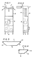
- the air cleaning apparatus 1 shown in Figures 1 and 2 has an air suction port 2 at the bottom of a columnar body 5, a blower 3 above the suction port 2 for circulating the air, an air cleaner or filter 4 for collecting dust above the blower 3 in the body 5, and a clear air duct 7 connected to and extending horizontally away from the upper end of the body 5 and having clean air diffuser outlets 6 in the side and lower surfaces thereof, from which clean air is discharged as indicated by the arrows in Figure 1.
- the duct 7 is substantially trapezoidal in cross-section and may taper at each side face as shown in Figure 3 or at one side face only as shown in Figure 4.
- Diffuser outlets 6 in the form of perforations or openings in the duct wall are distributed along the lower face and tapered side face ( Figure 4) or faces ( Figure 3). Perforations or openings may be provided over substantially the entire area of these faces in order to obtain the required discharge and diffusion of clean air into the room.
- the cross-sectional shape of the duct 7 depends upon the intended disposition of the air cleaning apparatus within the room. It will, for example, be understood, that the duct shown in Figure 4 is suitable when the duct 7 is to be disposed in the corner between a wall and the ceiling of a room.
- plates which are perforate or porous, to provide diffuser outlets 6, are secured by screws or bolts 10 and/or by a hinge or hinges (not shown).
- the air cleaning filter 4 is installed in the body 5 above the blower 3.
- the filter 4 may, however, be arranged in any suitable position. It may, for example, be arranged in the vicinity of the inlet end of the duct 7 or in the vicinity of the air diffuser outlets 6.
- Air cleaning apparatus may have any number of columnar bodies 5 and ducts 7 and these may be connected together in any desired configuration, for example, an inverted L shape in which the duct 7 extends laterally of the body 5 as shown in Figure 1, a T-shape in which the duct 7 extends horizontally from both sides as shown in Figure 5, an inverted U-shape in which the duct 7 bridges two columnar bodies as shown in Figure 6, or an E-shape having three columnar bodies 5 and two ducts 7 as shown in Figure 7.
- the particular configuration is selected according to the shape and the size of the room to be cleaned.
- the apparatus may also include an air conditioner housed within the body 5.
- the air in the room to be cleaned is drawn by the. blower 3 through the air suction port 2 into the body 5, and is then fed through the filter 4 to remove entrained dust, before passing through a sterilizer or pasteurizer if provided. Clean air thus treated is then fed into the duct 7 and passed through the diffuser outlets 6 into the room. There is constant recirculation of the air through the air cleaning apparatus 1 in the manner described above so as to keep the air in the room clean.
- FIGs 8, 9 and 10 show a preferred arrangement of air cleaning apparatus 1 within a room to be cleaned.
- Each of the three apparatus units has a generally U-shaped configuration as shown in Figure 6, the units being disposed one at each end and one midway along the length of the room R.
- the bodies 5 of the units 1 are clamped to the walls 8 by a simple means such as bolts and nuts and the ducts 7 extend along the lower surface of a ceiling 9.
- the units 1 may be built or designed in advance for installation on site, with the dimensions of the bodies 5 and the ducts 7 adapted to suit the dimensions of the room R.
- the air cleaning units la at opposite ends of the room each have two bodies 6 and a single duct 7 extending along the ceiling in the corner between the ceiling and the wall.
- the duct section is of inverted trapezoidal shape with one tapered side as shown in Figure 4.
- the air cleaning unit 1b arranged midway along the room is of the type having the duct section which is also of inverted trapezoidal shape but with two tapered sides as shown in Figure 3. Clean air can thus be diffused into all areas of the room R as illustrated by the arrows in Figure 8.
- the air cleaning units shown in Figure 5 and 7 may be disposed in the middle of a room R as shown in Figures 11 and 12.
- the duct section 7 is of inverted trapezoidal shape with two tapered sides.
- an external air treating unit 11 is connected, via a water supply pipe passing through the wall to the body 5 of the air cleaning apparatus.
- an air conditioner may be installed in the body 5 of the air cleaning apparatus, this being connected by pipe 12 to the outer atmospheric air treating unit 12.
- the installation of the air cleaning apparatus involves merely arranging and assembling columnar bodies and ducts selected according to the size and shape of the room, in the desired configuration, with the duct(s) extending from the body(ies) along the lower surface of the ceiling, and clamping the apparatus, using screws, bolts or nuts or other suitable fixing devices, to the walls, ceiling and/or floors as appropriate.
- any room in an existing building can be converted to a clean room regardless of the shape and the size of the room, the time required for and hence also the cost of installation is significantly less than with conventional installations.
- Checking, cleaning and maintenance of the air cleaning apparatus is facilitated by virtue of the fact that the apparatus is readily accessible within the room.
Landscapes
- Engineering & Computer Science (AREA)
- Chemical & Material Sciences (AREA)
- Combustion & Propulsion (AREA)
- Mechanical Engineering (AREA)
- General Engineering & Computer Science (AREA)
- Ventilation (AREA)
- Central Air Conditioning (AREA)
- Duct Arrangements (AREA)
Applications Claiming Priority (2)
| Application Number | Priority Date | Filing Date | Title |
|---|---|---|---|
| JP155076/82 | 1982-09-06 | ||
| JP57155076A JPS5944538A (ja) | 1982-09-06 | 1982-09-06 | クリ−ンル−ム用クリ−ンユニツトおよびクリ−ンル−ムシステム |
Publications (3)
| Publication Number | Publication Date |
|---|---|
| EP0107298A2 true EP0107298A2 (fr) | 1984-05-02 |
| EP0107298A3 EP0107298A3 (en) | 1984-09-26 |
| EP0107298B1 EP0107298B1 (fr) | 1987-12-09 |
Family
ID=15598125
Family Applications (1)
| Application Number | Title | Priority Date | Filing Date |
|---|---|---|---|
| EP83305038A Expired EP0107298B1 (fr) | 1982-09-06 | 1983-09-01 | Appareil pour la purification d'air |
Country Status (6)
| Country | Link |
|---|---|
| EP (1) | EP0107298B1 (fr) |
| JP (1) | JPS5944538A (fr) |
| AU (1) | AU577262B2 (fr) |
| DE (1) | DE3374898D1 (fr) |
| HK (1) | HK5591A (fr) |
| SG (1) | SG97390G (fr) |
Cited By (4)
| Publication number | Priority date | Publication date | Assignee | Title |
|---|---|---|---|---|
| EP0180139A3 (en) * | 1984-10-23 | 1987-04-22 | Shimizu Kensetsu Kabushiki Kaisha | Clean room |
| EP0510946A3 (en) * | 1991-04-23 | 1993-07-07 | Kawasaki Steel Corporation | Air supplying apparatus |
| WO2001031261A1 (fr) * | 1999-10-29 | 2001-05-03 | Mobiroom Aktiebolag | Salle a environnement de travail |
| EP4269900A1 (fr) * | 2022-04-28 | 2023-11-01 | Air'technologies | Conduit diffuseur pour diffuser de l'air conditionné |
Families Citing this family (8)
| Publication number | Priority date | Publication date | Assignee | Title |
|---|---|---|---|---|
| JPS61101732A (ja) * | 1984-10-23 | 1986-05-20 | Shimizu Constr Co Ltd | クリ−ンル−ム |
| JPS6231229U (fr) * | 1985-08-08 | 1987-02-25 | ||
| JPH0531468Y2 (fr) * | 1986-05-12 | 1993-08-12 | ||
| JPS6375735U (fr) * | 1986-11-06 | 1988-05-20 | ||
| JPS6387448U (fr) * | 1986-11-26 | 1988-06-07 | ||
| AU597470B2 (en) * | 1988-02-02 | 1990-05-31 | Hirayama Setsubi Kabushiki Kaisha | Clean room system |
| JP4165056B2 (ja) * | 2001-11-09 | 2008-10-15 | 松下電工株式会社 | 医療用コンソール |
| BE1032646B1 (nl) * | 2024-05-01 | 2026-01-12 | Abn Cleanroom Tech N V | Systeem voor het ventileren van een klimaatkamer |
Family Cites Families (4)
| Publication number | Priority date | Publication date | Assignee | Title |
|---|---|---|---|---|
| DE7430376U (de) * | 1975-01-23 | Bosch R Gmbh | Gebläsekonvektor für Raumheizung bzw.-klimatisierung | |
| LU38777A1 (fr) * | 1959-09-08 | 1960-08-08 | ||
| DE1259076B (de) * | 1965-12-22 | 1968-01-18 | Krantz H Fa | Vorrichtung zum Klimatisieren von Raeumen mit hoher Waermebelastung, insbesondere von Ringspinn- und Zwirnmaschinensaelen |
| DE3028143A1 (de) * | 1979-09-13 | 1981-04-02 | Luwa AG, Zürich | Luftverteileinrichtung insbesondere fuer uebersaettigte luft |
-
1982
- 1982-09-06 JP JP57155076A patent/JPS5944538A/ja active Granted
-
1983
- 1983-09-01 DE DE8383305038T patent/DE3374898D1/de not_active Expired
- 1983-09-01 EP EP83305038A patent/EP0107298B1/fr not_active Expired
- 1983-09-05 AU AU18708/83A patent/AU577262B2/en not_active Ceased
-
1990
- 1990-12-06 SG SG973/90A patent/SG97390G/en unknown
-
1991
- 1991-01-17 HK HK55/91A patent/HK5591A/xx unknown
Cited By (4)
| Publication number | Priority date | Publication date | Assignee | Title |
|---|---|---|---|---|
| EP0180139A3 (en) * | 1984-10-23 | 1987-04-22 | Shimizu Kensetsu Kabushiki Kaisha | Clean room |
| EP0510946A3 (en) * | 1991-04-23 | 1993-07-07 | Kawasaki Steel Corporation | Air supplying apparatus |
| WO2001031261A1 (fr) * | 1999-10-29 | 2001-05-03 | Mobiroom Aktiebolag | Salle a environnement de travail |
| EP4269900A1 (fr) * | 2022-04-28 | 2023-11-01 | Air'technologies | Conduit diffuseur pour diffuser de l'air conditionné |
Also Published As
| Publication number | Publication date |
|---|---|
| EP0107298B1 (fr) | 1987-12-09 |
| JPS5944538A (ja) | 1984-03-13 |
| HK5591A (en) | 1991-01-25 |
| JPH0348417B2 (fr) | 1991-07-24 |
| AU1870883A (en) | 1984-03-15 |
| EP0107298A3 (en) | 1984-09-26 |
| DE3374898D1 (en) | 1988-01-21 |
| SG97390G (en) | 1991-02-14 |
| AU577262B2 (en) | 1988-09-22 |
Similar Documents
| Publication | Publication Date | Title |
|---|---|---|
| EP1146841B1 (fr) | Procede et dispositif permettant de ventiler une salle blanche | |
| EP0107298A2 (fr) | Appareil pour la purification d'air | |
| US4560395A (en) | Compact blower and filter assemblies for use in clean air environments | |
| EP0196333B1 (fr) | Systeme de construction de salles blanches | |
| US4461205A (en) | Combination lighting and filtering unit for a clean room | |
| JP3357377B2 (ja) | フアンフイルータユニットからのノイズを最小にするための方法並びに装置 | |
| KR102074612B1 (ko) | 환기형 시스템 공기정화기 | |
| KR20010050463A (ko) | 제약업, 식품업 및 생명공학 분야를 위한 청정공기설비 | |
| IE74881B1 (en) | Filter/ventilator apparatus for use in clean rooms | |
| EP0410428A2 (fr) | Système de collecteur pour la poussière dans des tunnels | |
| JP2575429B2 (ja) | 空気冷却式電気機器の室内排気装置 | |
| US4854224A (en) | Air cleaning apparatus and construction of clean room with the same | |
| US4841847A (en) | Air cleaning apparatus and construction of clean room with the same | |
| US5222871A (en) | Compressed air and underpressure supply unit | |
| JPH0351647A (ja) | クリーンルーム構築システム | |
| CN112240073B (zh) | 用于构造洁净室的天花板模块 | |
| CA2624706C (fr) | Procede d'exploitation d'une pluralite de salles blanches | |
| JPS62186149A (ja) | クリ−ンル−ムにおける空気清浄装置 | |
| JP2006292220A (ja) | クリーンルーム | |
| JPS61168735A (ja) | クリ−ンル−ム | |
| JP2739672B2 (ja) | 建造物の給排気設備 | |
| JPS58127034A (ja) | 清浄作業室 | |
| JPS62194140A (ja) | クリ−ンル−ム | |
| KR0175689B1 (ko) | 청결실용 청정장치의 지지구조 | |
| SU1260643A1 (ru) | Способ вентил ции производственного помещени |
Legal Events
| Date | Code | Title | Description |
|---|---|---|---|
| PUAI | Public reference made under article 153(3) epc to a published international application that has entered the european phase |
Free format text: ORIGINAL CODE: 0009012 |
|
| AK | Designated contracting states |
Designated state(s): DE FR GB IT |
|
| PUAL | Search report despatched |
Free format text: ORIGINAL CODE: 0009013 |
|
| AK | Designated contracting states |
Designated state(s): DE FR GB IT |
|
| 17P | Request for examination filed |
Effective date: 19850325 |
|
| GRAA | (expected) grant |
Free format text: ORIGINAL CODE: 0009210 |
|
| AK | Designated contracting states |
Kind code of ref document: B1 Designated state(s): DE FR GB IT |
|
| ITF | It: translation for a ep patent filed | ||
| REF | Corresponds to: |
Ref document number: 3374898 Country of ref document: DE Date of ref document: 19880121 |
|
| ET | Fr: translation filed | ||
| PLBE | No opposition filed within time limit |
Free format text: ORIGINAL CODE: 0009261 |
|
| STAA | Information on the status of an ep patent application or granted ep patent |
Free format text: STATUS: NO OPPOSITION FILED WITHIN TIME LIMIT |
|
| 26N | No opposition filed | ||
| ITTA | It: last paid annual fee | ||
| PGFP | Annual fee paid to national office [announced via postgrant information from national office to epo] |
Ref country code: FR Payment date: 19931230 Year of fee payment: 11 |
|
| PGFP | Annual fee paid to national office [announced via postgrant information from national office to epo] |
Ref country code: GB Payment date: 19941209 Year of fee payment: 12 |
|
| PG25 | Lapsed in a contracting state [announced via postgrant information from national office to epo] |
Ref country code: FR Effective date: 19950531 |
|
| REG | Reference to a national code |
Ref country code: FR Ref legal event code: ST |
|
| PG25 | Lapsed in a contracting state [announced via postgrant information from national office to epo] |
Ref country code: GB Effective date: 19950901 |
|
| PGFP | Annual fee paid to national office [announced via postgrant information from national office to epo] |
Ref country code: DE Payment date: 19960322 Year of fee payment: 13 |
|
| GBPC | Gb: european patent ceased through non-payment of renewal fee |
Effective date: 19950901 |
|
| PG25 | Lapsed in a contracting state [announced via postgrant information from national office to epo] |
Ref country code: DE Effective date: 19970603 |