EP0107499A2 - Buse de pulvérisation électrostatique - Google Patents
Buse de pulvérisation électrostatique Download PDFInfo
- Publication number
- EP0107499A2 EP0107499A2 EP83306444A EP83306444A EP0107499A2 EP 0107499 A2 EP0107499 A2 EP 0107499A2 EP 83306444 A EP83306444 A EP 83306444A EP 83306444 A EP83306444 A EP 83306444A EP 0107499 A2 EP0107499 A2 EP 0107499A2
- Authority
- EP
- European Patent Office
- Prior art keywords
- paint
- air
- nozzle
- spout hole
- spray nozzle
- Prior art date
- Legal status (The legal status is an assumption and is not a legal conclusion. Google has not performed a legal analysis and makes no representation as to the accuracy of the status listed.)
- Withdrawn
Links
- 239000007921 spray Substances 0.000 title claims abstract description 34
- 239000003973 paint Substances 0.000 claims abstract description 117
- 239000002245 particle Substances 0.000 claims abstract description 13
- 230000008021 deposition Effects 0.000 claims abstract description 8
- 238000007664 blowing Methods 0.000 claims abstract description 4
- 238000010926 purge Methods 0.000 claims description 9
- 238000000889 atomisation Methods 0.000 abstract description 10
- 239000007788 liquid Substances 0.000 abstract description 5
- 230000001737 promoting effect Effects 0.000 abstract description 2
- 239000004020 conductor Substances 0.000 description 7
- 238000000151 deposition Methods 0.000 description 7
- 239000011248 coating agent Substances 0.000 description 4
- 238000000576 coating method Methods 0.000 description 4
- 238000010276 construction Methods 0.000 description 2
- 239000002184 metal Substances 0.000 description 2
- 239000004809 Teflon Substances 0.000 description 1
- 229920006362 Teflon® Polymers 0.000 description 1
- 230000007547 defect Effects 0.000 description 1
- 230000000694 effects Effects 0.000 description 1
- 230000008030 elimination Effects 0.000 description 1
- 238000003379 elimination reaction Methods 0.000 description 1
- 230000002708 enhancing effect Effects 0.000 description 1
- 230000002093 peripheral effect Effects 0.000 description 1
- 239000012858 resilient material Substances 0.000 description 1
- 230000000717 retained effect Effects 0.000 description 1
- 229920003002 synthetic resin Polymers 0.000 description 1
- 239000000057 synthetic resin Substances 0.000 description 1
- 238000005406 washing Methods 0.000 description 1
Images


Classifications
-
- B—PERFORMING OPERATIONS; TRANSPORTING
- B05—SPRAYING OR ATOMISING IN GENERAL; APPLYING FLUENT MATERIALS TO SURFACES, IN GENERAL
- B05B—SPRAYING APPARATUS; ATOMISING APPARATUS; NOZZLES
- B05B5/00—Electrostatic spraying apparatus; Spraying apparatus with means for charging the spray electrically; Apparatus for spraying liquids or other fluent materials by other electric means
- B05B5/025—Discharge apparatus, e.g. electrostatic spray guns
- B05B5/03—Discharge apparatus, e.g. electrostatic spray guns characterised by the use of gas, e.g. electrostatically assisted pneumatic spraying
Definitions
- This invention relates to an electrostatic spray nozzle for electrostatically coating a work with a paint by applying a high voltage to the paint along with jets of pressurized air.
- the airless type spray nozzle which is adapted to spurt a paint under a predetermined pressure toward a work from a labial paint spout hole provided in a paint nozzle.
- the airless type spray nozzle of this sort usually requires to pressurize a paint up to a high liquid pressure level of about 100 - 300 kg/cm 2 , so that there arises a necessity for employing a paint pump and a hose which can endure a high liquid pressure, coupled with a problem that the paint spout hole is considerably worn out by the liquid flows of high velocity.
- the conventional airless type spray nozzle has a problem that the so-called "tailing phenomenon" appears at the opposite ends of a paint spray pattern, which impairs the quality of coating.
- the air blow hole is provided rearward or sideward of a paint spout hole in order not to disturb the paint jets from the paint spout hole, so that there is still a problem that it is difficult to collide the air streams against the paint jets in a sufficient degree, resulting in a low atomization efficiency.
- an air blow hole is provided forward of the paint spout hole, there is also a problem that jet streams of the paint are wastefully scattered away, failing to coat a workpiece in a sufficient degree and thus lowering the efficiency of paint deposition.
- the present invention aims at elimination of the above-mentioned defects or problems of the prior art, and has as its object the provision of an electrostatic spray nozzle which can form a coating of high quality with a high efficiency.
- an electrostatic spray nozzle which is characterized by the provision of: a paint nozzle having a labial paint spout hole for spurting a paint under predetermined liquid pressure; an air nozzle having a labial air blow hole forwardly of the paint spout hole for blowing air streams toward the paint spurted from the paint spout hole to accelerate atomization of the paint; and a needle electrode located forward of the air spout hole and applied with a high voltage for electrically charging the atomized particles of the paint sprayed by the air jets.
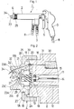
- a hand gun type electrostatic sprayer employing the spray nozzle according to the present invention
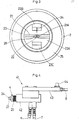
- the hand gun type electrostatic sprayer including a nozzle body 2 internally provided with a paint passage and an air passage as described later, a handle 3 provided at one end of the nozzle body 2, an electrostatic spray nozzle 4 provided at the other end of the nozzle body 2 in the manner as explained later with reference to Figures 2 and 3, a trigger 5 for manual operation located between the nozzle body 2 and handle 3 for manually opening and closing the paint and air passages, a paint hose 6 and an air hose 7 connected to the nozzle body 2, and a high voltage cable 8 for receiving a supply of high voltage from a high voltage generator (not shown).
- the nozzle body 2 is internally provided with a paint passage 11 which communicates with the paint hose 6 and an air passage 12 which communicates with the air hose 7 and an annular groove 13 is formed on an end face 2A of the nozzle body 2.
- valve rod 14 which has one end thereof connected to the trigger 5 and has a valve member 15 mounted at the other end, so that the valve member 15 is moved toward and away from a valve seat 16 by manipulation of the trigger 5 to open and close the paint passage 11, in synchronism with another valve mechanism which is also operated by the trigger 5 to open and close the air passage 12.
- Designated at 17 is a nozzle holder which is provided on the end face 2A of the nozzle body 2, the nozzle holder 17 being formed in a semi-spherical shape and provided with a plural number of axial air passages 18 in communication with the annular passage 13.
- An intermediate seat member 19 of a resilient material such as Teflon and the like which is fitted in the nozzle holder 17 is centrally provided with an axial paint passage 20 in communication with the paint passage 11.
- the reference numeral 21 denotes a paint nozzle which is fitted in the nozzle holder 17 with its distal spherical portion 21A projected forwardly out of the nozzle holder 17.
- the paint nozzle 21 is retained in position by the intermediate seat member 19, gripped between the intermediate seat member 19 and the nozzle. holder 17.
- the paint nozzle 21 is provided with a labial paint spout hole 22 which is formed by cutting the spherical portion 21A in V-shape in section.
- a paint which is supplied through the paint passages 14 and 20 is spurted from the paint spout hole 22 in the form of a jet stream of sectoral shape.
- Designated at 23 is an air nozzle which is formed with a concave surface 24 on one side thereof, and located in such a manner as to circumvent the paint nozzle 21 as well as the nozzle holder 17.
- the air nozzle 23 is gripped between the end face 2A of the nozzle body 2 and the nut 25, while shoulders 17A of the nozzle holder 17 are abutted on the concave surface 24, gripping the nozzle holder 17 between the concave surface 24 and the end face 2A and thus as a-whole securing the nozzle holder 17 and air nozzle 23 to the nozzle holder 2.
- the air nozzle 23 is formed with a labial air blow hole 26 at a position forward of the distal spherical portion 21A of the paint nozzle 21.
- the air blow hole 26 is formed by cutting a groove of V -shape 27 across a center plateau 23A (see Figure 3) to define a labial opening between the V-shaped groove 27 and the concave surface 24.
- the angle 8 of the v-groove 27 is set at the same value as the V-shaped labial paint spout hole 22.
- annular groove 28 which communicates with the air passage 18 is formed between the outer peripheral surface of the nozzle holder 17 and the spherical concave surface 24 of the air nozzle 23, and the nozzle holder 17 is provided with a head portion 17B of a diameter which is reduced toward the air blow hole 26 and smaller than the abutting shoulder portion 17A, defining an air passage 29 between the head portion 17B and the spherical concave surface 24 around the entire circumference of the head portion 17B.
- a high resistance which is provided in the nozzle body 2 for safety purposes, one end of the high resistance 30 being connected to the high voltage cable 8 and the other end to a conductor 31 which is extended to the end face 2A of the nozzle body 2.
- Denoted at 32 is a conductor which is embedded in the air nozzle 23 and has one end thereof connected to the conductor 31 through a connecting spring 33, forming a needle electrode 34 at the other end which is projected from a horn portion 23B of the air nozzle 23 at a position forward of the air blow hole 26.
- the valve 15 is opened by manipulation of the trigger 5 to supply a paint from the hose 6 to the paint nozzle 21 under a pressure of, for example, 50 kg/cm 2 through the paint passages 11 and 20, shooting the paint toward the air blow hole 26 from the paint spout hole 22 in the form of a jet stream of sectoral shape of the angle 9.
- the air passage 12 is also opened, and pressurized air from the air hose 7 is supplied to the air nozzle 23 under a pressure of, for example, 2 kg/cm 2 through the air passage 12, annular groove 13, air passage 18, annular groove 28 and air passage 29, spurting from the air blow hole 26 an air stream of sectoral shape of the angle 8.
- the paint spout hole 22 and air blow hole 26 are formed by V -shaped grooves of the same angle, so that the paint which is spurted out from the paint spout hole 22 is securely guided toward the air blow hole 26, without spoiling the air nozzle by depositing on the spherical concave surface 24 on the inner side of the air nozzle, especially the marginal edge portions of the air blow hole 26.
- the needle electrode 34 which is located forward of the air blow hole 26 is applied with a high voltage, for example, a voltage of minus 90 KV through the high voltage cable 8, high resistance 30, conductor 31, spring 33 and conductor 32. Therefore, air around the needle electrode 34 is negatively ionized, forming an ionized zone therearound, so that the paint particles are negatively charged as they pass through the ionized zone and urged to fly toward a workpiece along lines of electric force. Consequently, the charged paint particles are caused to go around even to the back side of the workpiece, enhancing the efficiency of paint deposition to a considerable degree.
- a high voltage for example, a voltage of minus 90 KV
- the high voltage cable 8 high resistance 30, conductor 31, spring 33 and conductor 32. Therefore, air around the needle electrode 34 is negatively ionized, forming an ionized zone therearound, so that the paint particles are negatively charged as they pass through the ionized zone and urged to fly toward a workpiece along lines of electric force. Consequently, the charged paint particles
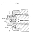
- the paint spray nozzle according to the present invention is not limited to a hand gun type sprayer and may be applied to an auto gun type electrostatic sprayer 41 as shown in Figure 4.
- the electrostatic sprayer 41 employs a nozzle body 42 which is internally provided with an air drive type valve operating mechanism instead of a manual trigger.
- the nozzle body 42 is provided with an electrostatic spray nozzle 4, a paint hose 6 and an air hose 7.
- the nozzle body 42 is provided with an arm 43 to be attached to a reciprocator or the like, mounting on the arm 43 an attaching bracket 44 and a high voltage cable 8.
- the nozzle body 42, the paint spray nozzle 6 and the like may be formed of a conductive metal if desired.
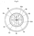
- FIG. 5 there is shown a second embodiment of the invention, which is arranged to prevent deposition of paint on the center plateau 123A of the air nozzle 123, namely, on the surface 123B which faces a workpiece.
- the air nozzle 123 is provided with a plural number of air holes 135 in the center plateau 123A for blowing off paint purge air therefrom.
- Each air hole 135 is opened at one end into an air passage 129 and at the other end into the plateau face 123B which faces the workpiece.
- a plural number of air holes 135 are arranged in parallel rows which are located on opposite sides of the V-shaped groove 127.
- pressurized air is blown off not only from the air blow hole 126 but also from the air holes 135 during a coating operation to send forth paint purge air therefrom.
- the paint purge air suitably prevents paint deposition on the end face 123B as well as spitting, contributing to the improvement in quality of coated products and to the reduction of the washing time of the paint spray nozzle.
- paint purge air may be supplied in the manner as shown in Figures 7 and 8.
- a semi-circular projection 223D may be provided on the plateau surface 223B of the air nozzle which faces a workpiece, on one side of the opposing horn portions 223C and 223C' (on the left side in the case of Figure 8) and across the V -shaped groove 227, the semi-circular projection 223D having a height greater than the height in the axial direction-of the plateau surface 223B but smaller than the height of the horn portions 223C and 223C' and being provided with a straight or upright wall 223E on the side of the horn portions 223C and 223C'.
- the air nozzle 223 is likewise provided with a pair of paint purge air holes 235 on the opposite sides of the V-groove 227.
- Each paint purge air hole 235 is opened at one end thereof into the air passage 229 and has the other end curved in the semi-circular projection 223 and opened on the upright wall 223E (see Figure 7).
- the paint purge air can be blown off from the air holes 235 substantially in a direction parallel with the plateau surface 223B, so that the plateau surface 223 B can be constantly covered with paint purge air during operation, preventing the deposition of paint particles on the plateau surface 223B which would otherwise be caused by vacuum pressure developing around the air stream from the air blow hole 226.
- labial paint spout hole and the labial air blow hole have been described in the foregoing embodiments as being formed by cutting a V-shaped groove in the distal spherical portion of the paint nozzle and the center plateau of the air nozzle, respectively, they may be formed by a groove of U-shape in section if desired. Further, instead of providing a needle electrode on one horn portion, a pair of needle electrodes may be provided on the radially opposing two horn portions.
- a synthetic resin with an insulating property for the nozzle body, nozzle holder, air nozzle, cap and the like it is preferred from the standpoint of safety to use a synthetic resin with an insulating property for the nozzle body, nozzle holder, air nozzle, cap and the like.
Landscapes
- Electrostatic Spraying Apparatus (AREA)
- Nozzles (AREA)
Applications Claiming Priority (4)
| Application Number | Priority Date | Filing Date | Title |
|---|---|---|---|
| JP16218882U JPS5965762U (ja) | 1982-10-26 | 1982-10-26 | 静電噴霧ノズル |
| JP162188/82U | 1982-10-26 | ||
| JP171450/82U | 1982-11-12 | ||
| JP17145082U JPS5974859U (ja) | 1982-11-12 | 1982-11-12 | 塗料噴霧ノズル |
Publications (2)
| Publication Number | Publication Date |
|---|---|
| EP0107499A2 true EP0107499A2 (fr) | 1984-05-02 |
| EP0107499A3 EP0107499A3 (fr) | 1985-09-18 |
Family
ID=26488069
Family Applications (1)
| Application Number | Title | Priority Date | Filing Date |
|---|---|---|---|
| EP83306444A Withdrawn EP0107499A3 (fr) | 1982-10-26 | 1983-10-24 | Buse de pulvérisation électrostatique |
Country Status (2)
| Country | Link |
|---|---|
| EP (1) | EP0107499A3 (fr) |
| DE (1) | DE107499T1 (fr) |
Cited By (1)
| Publication number | Priority date | Publication date | Assignee | Title |
|---|---|---|---|---|
| DE19502522A1 (de) * | 1995-01-27 | 1996-08-01 | Gema Volstatic Ag | Sprühvorrichtung für Beschichtungsmaterial |
Family Cites Families (6)
| Publication number | Priority date | Publication date | Assignee | Title |
|---|---|---|---|---|
| SE361846B (fr) * | 1967-03-20 | 1973-11-19 | Ransburg Electro Coating Corp | |
| US3521824A (en) * | 1968-10-11 | 1970-07-28 | Delavan Manufacturing Co | Air-liquid flat spray nozzle |
| US3843052A (en) * | 1971-03-03 | 1974-10-22 | Electrogasdynamics | Pneumatically assisted hydraulic spray coating apparatus |
| US4036434A (en) * | 1974-07-15 | 1977-07-19 | Aerojet-General Corporation | Fluid delivery nozzle with fluid purged face |
| FR2350887A1 (fr) * | 1976-05-10 | 1977-12-09 | Air Ind | Buse de pulverisation de produits liquides |
| GB1600631A (en) * | 1978-01-10 | 1981-10-21 | Binks Bullows Ltd | Spray nozzle |
-
1983
- 1983-10-24 EP EP83306444A patent/EP0107499A3/fr not_active Withdrawn
- 1983-10-24 DE DE1983306444 patent/DE107499T1/de active Pending
Cited By (2)
| Publication number | Priority date | Publication date | Assignee | Title |
|---|---|---|---|---|
| DE19502522A1 (de) * | 1995-01-27 | 1996-08-01 | Gema Volstatic Ag | Sprühvorrichtung für Beschichtungsmaterial |
| US5686149A (en) * | 1995-01-27 | 1997-11-11 | Gema Volstatic Ag | Spray device and method for powder coating material |
Also Published As
| Publication number | Publication date |
|---|---|
| DE107499T1 (de) | 1984-12-06 |
| EP0107499A3 (fr) | 1985-09-18 |
Similar Documents
| Publication | Publication Date | Title |
|---|---|---|
| US4221339A (en) | Liquid spraying device | |
| US3746253A (en) | Coating system | |
| US5685482A (en) | Induction spray charging apparatus | |
| EP0938932B1 (fr) | Pistolet de pulvérisation thermique à arc électrique et son capuchon à gaz | |
| US3777981A (en) | Spray apparatus and method | |
| AU643192B2 (en) | Electrostatic rotary atomizing liquid spray coating apparatus | |
| US5687906A (en) | Atomization method and atomizer | |
| US4921172A (en) | Electrostatic sprayer device for spraying products in powder form | |
| JPH0510144B2 (fr) | ||
| GB2111406A (en) | Spray gun | |
| JPH1043644A (ja) | 静電吹付装置 | |
| US3677470A (en) | Nozzle holder | |
| JPH0889853A (ja) | コロナ放電方法および静電塗装装置 | |
| JPH0724367A (ja) | 回転霧化静電塗装方法およびその装置 | |
| US3590318A (en) | Powder coating apparatus producing a flat powder spray | |
| US7784718B2 (en) | Electrostatic paint sprayer | |
| US5686149A (en) | Spray device and method for powder coating material | |
| JPH07313907A (ja) | 静電吹き付け装置 | |
| US5765762A (en) | Spray gun type electrostatic paint coating machine | |
| US6276618B1 (en) | Electrostatic powder spray gun | |
| JPS61103560A (ja) | チツプ放電抵抗を持つエアレススプレガン | |
| US3844477A (en) | Electrostatic powder spray gun | |
| US4440349A (en) | Electrostatic spray gun having increased surface area from which fluid particles can be formed | |
| US3692241A (en) | Spray apparatus with atomization device | |
| EP0107499A2 (fr) | Buse de pulvérisation électrostatique |
Legal Events
| Date | Code | Title | Description |
|---|---|---|---|
| PUAI | Public reference made under article 153(3) epc to a published international application that has entered the european phase |
Free format text: ORIGINAL CODE: 0009012 |
|
| AK | Designated contracting states |
Designated state(s): DE FR GB IT |
|
| EL | Fr: translation of claims filed | ||
| DET | De: translation of patent claims | ||
| ITCL | It: translation for ep claims filed |
Representative=s name: BARZANO' E ZANARDO ROMA S.P.A. |
|
| REG | Reference to a national code |
Ref country code: DE Ref legal event code: 8580 Free format text: DER 2. ANMELDER IST NACHZUTRAGEN: ALLOY KOHKI CO. LTD., KAWASAKI, KANAGAWA, JP |
|
| PUAL | Search report despatched |
Free format text: ORIGINAL CODE: 0009013 |
|
| AK | Designated contracting states |
Designated state(s): DE FR GB IT |
|
| STAA | Information on the status of an ep patent application or granted ep patent |
Free format text: STATUS: THE APPLICATION IS DEEMED TO BE WITHDRAWN |
|
| 18D | Application deemed to be withdrawn |
Effective date: 19860520 |
|
| RIN1 | Information on inventor provided before grant (corrected) |
Inventor name: SAKUMA, HIDEO Inventor name: SAITO, EIJI |