EP0107779A1 - Tube trachéal avec un tube intérieur amovible - Google Patents
Tube trachéal avec un tube intérieur amovible Download PDFInfo
- Publication number
- EP0107779A1 EP0107779A1 EP83109261A EP83109261A EP0107779A1 EP 0107779 A1 EP0107779 A1 EP 0107779A1 EP 83109261 A EP83109261 A EP 83109261A EP 83109261 A EP83109261 A EP 83109261A EP 0107779 A1 EP0107779 A1 EP 0107779A1
- Authority
- EP
- European Patent Office
- Prior art keywords
- cannula
- inner cannula
- outer cannula
- connector
- tip
- Prior art date
- Legal status (The legal status is an assumption and is not a legal conclusion. Google has not performed a legal analysis and makes no representation as to the accuracy of the status listed.)
- Granted
Links
- 210000003437 trachea Anatomy 0.000 claims description 15
- 230000033001 locomotion Effects 0.000 claims description 10
- 206010002091 Anaesthesia Diseases 0.000 claims description 8
- 230000037005 anaesthesia Effects 0.000 claims description 8
- 230000000241 respiratory effect Effects 0.000 claims description 8
- 238000000465 moulding Methods 0.000 claims description 7
- 238000003780 insertion Methods 0.000 claims description 4
- 230000037431 insertion Effects 0.000 claims description 4
- 238000001949 anaesthesia Methods 0.000 claims 1
- 230000008878 coupling Effects 0.000 abstract description 28
- 238000010168 coupling process Methods 0.000 abstract description 28
- 238000005859 coupling reaction Methods 0.000 abstract description 28
- 239000000463 material Substances 0.000 abstract description 11
- 229920000915 polyvinyl chloride Polymers 0.000 abstract description 6
- 239000004800 polyvinyl chloride Substances 0.000 abstract description 6
- 239000003570 air Substances 0.000 description 18
- 238000007789 sealing Methods 0.000 description 17
- 238000000034 method Methods 0.000 description 11
- 238000004519 manufacturing process Methods 0.000 description 8
- 239000004743 Polypropylene Substances 0.000 description 4
- 238000004140 cleaning Methods 0.000 description 4
- 230000006378 damage Effects 0.000 description 4
- -1 polypropylene Polymers 0.000 description 4
- 229920001155 polypropylene Polymers 0.000 description 4
- 230000029058 respiratory gaseous exchange Effects 0.000 description 4
- 206010033372 Pain and discomfort Diseases 0.000 description 3
- 238000010276 construction Methods 0.000 description 3
- 238000002347 injection Methods 0.000 description 3
- 239000007924 injection Substances 0.000 description 3
- 239000002861 polymer material Substances 0.000 description 3
- 239000003994 anesthetic gas Substances 0.000 description 2
- 238000005452 bending Methods 0.000 description 2
- 230000001965 increasing effect Effects 0.000 description 2
- 238000001746 injection moulding Methods 0.000 description 2
- 230000007794 irritation Effects 0.000 description 2
- 210000003097 mucus Anatomy 0.000 description 2
- 230000036407 pain Effects 0.000 description 2
- 210000003800 pharynx Anatomy 0.000 description 2
- 229920003023 plastic Polymers 0.000 description 2
- 239000004033 plastic Substances 0.000 description 2
- 230000001954 sterilising effect Effects 0.000 description 2
- BHMLFPOTZYRDKA-IRXDYDNUSA-N (2s)-2-[(s)-(2-iodophenoxy)-phenylmethyl]morpholine Chemical compound IC1=CC=CC=C1O[C@@H](C=1C=CC=CC=1)[C@H]1OCCNC1 BHMLFPOTZYRDKA-IRXDYDNUSA-N 0.000 description 1
- 229920001634 Copolyester Polymers 0.000 description 1
- 206010062717 Increased upper airway secretion Diseases 0.000 description 1
- 208000027418 Wounds and injury Diseases 0.000 description 1
- 238000005299 abrasion Methods 0.000 description 1
- 230000035508 accumulation Effects 0.000 description 1
- 238000009825 accumulation Methods 0.000 description 1
- 239000012080 ambient air Substances 0.000 description 1
- 230000008933 bodily movement Effects 0.000 description 1
- 210000003103 bodily secretion Anatomy 0.000 description 1
- 210000004081 cilia Anatomy 0.000 description 1
- 238000004891 communication Methods 0.000 description 1
- 238000005520 cutting process Methods 0.000 description 1
- 230000003247 decreasing effect Effects 0.000 description 1
- 239000013536 elastomeric material Substances 0.000 description 1
- 238000005485 electric heating Methods 0.000 description 1
- 230000008030 elimination Effects 0.000 description 1
- 238000003379 elimination reaction Methods 0.000 description 1
- 230000002708 enhancing effect Effects 0.000 description 1
- 238000001125 extrusion Methods 0.000 description 1
- 239000007789 gas Substances 0.000 description 1
- 208000014674 injury Diseases 0.000 description 1
- 210000000867 larynx Anatomy 0.000 description 1
- 230000014759 maintenance of location Effects 0.000 description 1
- 239000000203 mixture Substances 0.000 description 1
- 231100000252 nontoxic Toxicity 0.000 description 1
- 230000003000 nontoxic effect Effects 0.000 description 1
- 230000002093 peripheral effect Effects 0.000 description 1
- 208000026435 phlegm Diseases 0.000 description 1
- 238000003825 pressing Methods 0.000 description 1
- 230000001105 regulatory effect Effects 0.000 description 1
- 230000028327 secretion Effects 0.000 description 1
- 239000002904 solvent Substances 0.000 description 1
- 238000004659 sterilization and disinfection Methods 0.000 description 1
- 238000001356 surgical procedure Methods 0.000 description 1
Images


Classifications
-
- A—HUMAN NECESSITIES
- A61—MEDICAL OR VETERINARY SCIENCE; HYGIENE
- A61M—DEVICES FOR INTRODUCING MEDIA INTO, OR ONTO, THE BODY; DEVICES FOR TRANSDUCING BODY MEDIA OR FOR TAKING MEDIA FROM THE BODY; DEVICES FOR PRODUCING OR ENDING SLEEP OR STUPOR
- A61M16/00—Devices for influencing the respiratory system of patients by gas treatment, e.g. ventilators; Tracheal tubes
- A61M16/04—Tracheal tubes
- A61M16/0465—Tracheostomy tubes; Devices for performing a tracheostomy; Accessories therefor, e.g. masks, filters
-
- A—HUMAN NECESSITIES
- A61—MEDICAL OR VETERINARY SCIENCE; HYGIENE
- A61M—DEVICES FOR INTRODUCING MEDIA INTO, OR ONTO, THE BODY; DEVICES FOR TRANSDUCING BODY MEDIA OR FOR TAKING MEDIA FROM THE BODY; DEVICES FOR PRODUCING OR ENDING SLEEP OR STUPOR
- A61M16/00—Devices for influencing the respiratory system of patients by gas treatment, e.g. ventilators; Tracheal tubes
- A61M16/04—Tracheal tubes
- A61M16/0402—Special features for tracheal tubes not otherwise provided for
- A61M16/0427—Special features for tracheal tubes not otherwise provided for with removable and re-insertable liner tubes, e.g. for cleaning
-
- A—HUMAN NECESSITIES
- A61—MEDICAL OR VETERINARY SCIENCE; HYGIENE
- A61M—DEVICES FOR INTRODUCING MEDIA INTO, OR ONTO, THE BODY; DEVICES FOR TRANSDUCING BODY MEDIA OR FOR TAKING MEDIA FROM THE BODY; DEVICES FOR PRODUCING OR ENDING SLEEP OR STUPOR
- A61M16/00—Devices for influencing the respiratory system of patients by gas treatment, e.g. ventilators; Tracheal tubes
- A61M16/04—Tracheal tubes
- A61M16/0488—Mouthpieces; Means for guiding, securing or introducing the tubes
- A61M16/0497—Tube stabilizer
Definitions
- the present invention relates to tracheostomy tubes having an outer cannula and a removable inner cannula, and, in particular, to a tracheostomy tube having a disposable inner cannula.
- Tracheostomy tubes have been used for some time to provide a bypass supply of air or mixture of gases to a patient having an obstruction in the larynx or the pharynx areas of the throat.
- the - distal end of the tracheostomy tube is inserted into the trachea through an incision in the patient's neck below the obstructed area.
- the proximal end of the tube remains outside the trachea in communication with ambient air to permit passage of such air into the trachea.
- This proximal end of the tube can also be attached to a respiratory device to assist the patient's breathing or to anesthesia equipment for passing anesthetic gas to the patient prior to surgery.
- a tracheostomy tube While thus in place within the patient's trachea, a tracheostomy tube can sometimes become partially or completely obstructed by accumulations of mucus or phlegm.
- U.S. Patent No. 3,698,624 to Shiley et al, assigned to Shiley, Inc., assignee of the present invention discloses and claims a tracheostomy tube which allows such obstructions to be cleared without causing pain and irritation to the patient, this invention providing an outer cannula, which remains in place in the trachea, and a removable inner cannula, which serves as an inner lining of the outer cannula.
- the inner cannula can be removed, cleaned, and then replaced.
- lined tracheostomy tubes which insures adequate cleaning, is that the inner cannula runs the entire length of the outer cannula.
- mucus could accumulate on and adhere to the unlined portion of the interior surface of the outer cannula, obstructing the air passage of the tube and requiring its complete removal for cleaning.
- the inner cannula should not extend substantially beyond the outer cannula, since removal and insertion of a protruding inner cannula could cause abrasion of the trachea and damage to the delicate cilia along the inner tracheal wall.
- the overall length of such removable inner cannulae must be carefully controlled.
- the tracheostomy tube of the present invention provides a disposable inner cannula, so that the time and expense associated with cleaning and sterilizing it can be eliminated.
- a significant feature of this invention is that each disposable inner cannula is dimensionally compatible with any particular outer cannula of the same type or size, while at the same time possessing the critical length and air seal characteristics mentioned above.
- the inner cannula is sufficiently inexpensive to manufacture to make disposability practical, and yet dimensional tolerances may be held sufficiently close to achieve interchangeability.
- a tapered distal portion on the inner cannula provides both an air seal with the outer cannula and a stop device for preventing the substantial protrusion of the inner cannula beyond the distal end of the outer cannula.
- the stop device compensates for variations in length among the present inner cannulae and maintains their dimensional compatibility with the outer cannulae.
- the tapered surface on the inner cannula faces and is located just behind the extreme distal tip of the inner cannula.
- the angle of inclination of the tapered surface is such that its diameter, at least at one point, is greater than the inside diameter of the narrowed distal end of the outer cannula.
- the stop device on the inner cannula is designed so that the inner cannula tip is flush with or extends only slightly beyond the end of the outer cannula.
- the position of the tip regardless of the length of the inner cannula, is controlled or regulated to fall within this narrow range.
- the tip is rounded.
- the inner cannula is constructed from a soft, biologically inactive polyvinyl chloride material, further protecting the patient's trachea. This material is also very flexible to permit the inner cannula of the present invention to bend within the outer cannula.
- the inner cannula is removably attached to the outer cannula by means of a coupling connector which advantageously snaps onto and off of the outer cannula with only minimal or essentially no longitudinal force, in order to prevent pain and discomfort to the patient.
- the coupling connector is mounted on the proximal end of the inner cannula by over-molding the cannula through the interior of the connector and fixing it in place by means of locking lugs.
- the connector may be bonded to the cannula, or the two can be integrally molded as a unitary element with a coupling ring snapped over the connector portion of the cannula.
- the coupling connector includes an integral male adaptor, which communicates with the bore of the inner cannula, . for receiving respiratory or anesthesia equipment.
- the connector and outer cannula are designed to allow an adequate degree, of rotational freedom of the connector relative to the outer cannula so that normal movement of the patient relative to the respiratory or anesthesia equipment is tolerated without causing any painful movement of the outer cannula.
- the nature of the coupling connection between the outer and inner cannulae is such that it provides for a secure attachment while permitting some longitudinal movement or "give" of the inner cannula with respect to the outer cannula.
- Inner cannulae so constructed are completely interchangeable, and at the same time provide an air seal with the outer cannula without extending substantially beyond it. That is, each inner cannula possesses a certain minimum length which is sufficient to permit the tapered sealing surface at its distal end to engage the outer cannula (thereby forming the air seal and stop devices) and to permit the coupling connector on its proximal end to snap onto the outer cannula.
- the stop device then serves to compensate for variations in length by preventing protrusion of the tip substantially beyond the outer cannula. Being secured at each end, the inner cannula further compensates for variations in length by virtue of its own flexibility and the longitudinal give permitted by the coupling connector.
- the inner cannula of the present invention which enhances its disposability, is the relative inexpense associated with the polymer materials and methods of manufacture from which it is constructed.
- the inner cannulae can be quickly and easily produced in large quantities using an injection molding process. Alternatively, they can be extruded and then end-formed using a Radio Frequency (RF) di-electric heating process.
- RF Radio Frequency
- dimensional tolerances are held close only in the distal area of the inner cannula to assure adequate sealing and stopping, since variations over its remaining length are offset as explained above.
- inner cannulae of the present invention need not be dimensionally customized to properly fit a particular outer cannula.
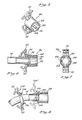
- FIGURES 1 and 2 there is shown the tracheostomy tube 10 of the pres.ent invention, including an outer cannula 12 and a removable inner cannula 14, shown partially removed in FIGURE 2.
- the cylindrical, arcuate outer cannula 12 is comprised of a distal end 16 for insertion into the trachea of the patient through an opening in the neck and a proximal end 18 remaining outside the trachea.
- an inflatable cuff 20 Shown attached to the tracheostomy tube 10 near its distal end 16 is an inflatable cuff 20 which, when inflated, provides an air tight seal between the tracheostomy tube 10 and the inner wall of the trachea.
- the cuff 20 is inflated by means of a flexible inflation tube 22 which extends into the cuff 20 from the proximal end 18 of the outer cannula 12.
- a swivel neck flange 24 located near the proximal end 18 of the outer cannula 12 is used to secure the tracheostomy tube 10 to the neck of the patient.
- the neck flange 24 is journaled in a pair of recessed openings 26 (FIGURE 2) in the outer cannula 12 to permit a degree of rotational freedom of the flange 24 and the patient's neck with respect to the outer cannula 12, significantly decreasing the pain and discomfort that may be caused by the patient's normal bodily movements.
- the inner cannula 14 is inserted into the bore 26 of the outer cannula 12 and secured in place by means of a coupling connector 28 mounted on its proximal end 30, as shown in FIGURE 2.
- the connector 28 which will be described in more detail in connection with FIGURE 4, is provided with a pair of resilient lever arms 32 which engage an annular retaining collar 34 located on the proximal end 18 of the outer cannula 12.
- the proximal end of the coupling connector 28 is provided with an opening 36 for receiving anesthesia equipment or artificial respiratory equipment (not shown) to assist the patient's breathing.
- the inner cannula 14 runs the entire length of the outer cannula 12 so that its distal tip 38 is flush with or slightly beyond the tapered necked-down portion 40 of the distal end 16 of the outer cannula 12 and the connector 28 is securely, releasably attached to the proximal end 18 of the outer cannula 12.
- a passageway 37 which communicates with the opening 36 of the connector 28 to permit air to flow into the trachea.
- FIGURE 3 is a partial sectional view taken through the distal end of the tracheostomy tube 10 of the present invention.
- a raised annular section 42 comprised of, from front to rear, a tapered, forwardly facing sealing surface 44, a non-tapered surface 46, and a tapered rearwardly facing surface 48.
- the sealing surface 44 is frustro-conical in shape and engages the interior surface 50 of the necked-down portion 40 on the distal end 16 of the outer cannula 12 to form a tight air seal between the outer cannula 12 and inner cannula 14.
- This sealing surface 44 is-sufficiently tapered so that at least one portion has an outer diameter which is greater than the inside diameter of the opening 52 of the outer cannula 12. Thus, only a slight axial force is required to wedge the sealing surface 44 of the inner cannula 14 into the opening 52 of the outer cannula 12 to form this air seal. Furthermore, it has been found that a sealing surface 44 having a slope A with respect to the horizontal of about 10-15 degrees is preferable, since within this range the inclination of the sealing surface 44 is sufficient to form a wedge-like seal with the necked-down portion 40 of the outer cannula 12, without creating an undesirably long sealing surface 44.
- the engagement between the inner cannula 14 and the outer cannula 12 also serves as a stop device to prevent the tip 38 of the inner cannula 14 from extending substantially beyond the distal tip 54 of the outer cannula 12.
- the sloping interior surface 50 of the necked-down portion 40 of the outer cannula 12 cooperates to form this stop device since it presents a large, relatively rigid obstacle to the raised portion 42 on the inner cannula 14 which prohibits substantial protrusion of the tip '38.
- the location and length of the sealing surface 44 on the inner cannula 14 and the size of opening 52 on the outer cannula 12, which toghether form the air seal and stop devices of the present invention, are such that the tip 38 will be flush with the tip 54 of the outer cannula if the interior surface 50 contacts the sealing surface 44 near its lower edge. If, on the other hand, the interior surface 50 contacts the upper edge of the sealing surface 44, the tip 38 will extend only slightly, e.g. about 1.3 millimetres, beyond the tip 54 of the outer cannula.
- the stop device of the present invention advantageously regulates the position of the tip 38 within this narrow range, thereby compensating for variations in overall length among the present inner cannulae.
- the trachea is further protected by the rounded shape of the tip 38 of the inner cannula 14 and by the soft, biologically compatable polymer material from which it is constructed. Moreover, the length of the inner cannula 14 is such that the tip 38 does not terminate within the opening 52 of the outer cannula 12. This construction ensures the proper elimination of obstructions in the passageway 37 of the tracheostomy tube 1 0 upon removal of the disposable inner cannula 14.
- the rear tapered surface 48 of the raised portion 42 facilitates removal of the inner cannula 14 from the opening 52 in the outer cannula 12.
- the length of the non-tapered surface 46 can be increased to provide extra strength and rigidity to the distal end of the inner cannula 14, and particularly to the sealing surface 44. Thus, this strength and rigidity will prevent the sealing surface 44 from collapsing and the tip 38 from extending too far beyond the tip 54 of the outer cannula.
- the length of this non-tapered surface 46 may be in the range of 1.5-3.0 millimetres, although other dimensions are also suitable.
- the inner cannula 14 of the present invention can be constructed from a soft, flexible, polymer material, preferably a non-toxic polyvinyl chloride having a Shore A hardness of about 85.
- a soft, biologically safe, elastomeric material having a Shore A hardness of 90 or less is also suitable.
- the inner cannula 14 can be inexpensively manufactured using plastic injection molding techniques or can be made in a two part process including an extrusion step followed by the di-electric end forming of the tip 38 and raised portion 42.
- either of the above-mentioned methods of manufacturing the inner cannula 14 produce a passageway 37 having a completely smooth interior surface 56.
- This feature reduces the frictional forces exerted on air and anesthetic gas delivered to the patient through the tracheostomy tube 10, thereby enhancing its efficiency.
- this smooth inner surface 56 provides for an essentially frictionless flow of bodily secretions which may enter the inner cannula 14, thus reducing the amount of such secretions which adhere to it and obstruct its passageway 56.
- the present inner cannula 14, to a degree is self-cleaning and must be replaced only infrequently.
- the outer diameter of the inner cannula 14 at points proximal to the raised portion 42 is sufficiently less than the inner diameter of the outer cannula 12 at corresponding locations to form a gap or space 58 within the bore 26 of the outer cannula 12, allowing the tracheostomy tube 10 of the present invention to further compensate for variations in length of the inner cannula 14 and to provide for its interchangeability.
- FIGURE 4 is a sectional view taken through the proximal end of the present tracheostomy tube 10, illustrating the outer cannula 12, the inner cannula 14 removably installed within the bore 26 of the outer cannula 12, and the coupling connector 28 mounted on the proximal end 30 of the inner cannula 14 for attaching it to the outer cannula 12.
- the connector 28 has a distal face 60 with an opening 62 to receive the inner cannula 14.
- the proximal face 64 .of the connector 28 is provided with a large opening 36 adapted to receive a conduit (not shown) from respiratory or anesthesia equipment which fits over the proximal end of the connector 28.
- the connector 28 can be inexpensively injected molded from copolyester or preferably, polypropylene material. As shown in FIGURE 4, the connector 28 can be bonded to the inner cannula 14 by a solvent or other suitable means. Two. alternative techniques for mounting the connector on the proximal end of the inner cannula are shown in FIGURES 5-8 and described in more detail below.
- a pair of lever arms 32 Integrally formed on opposite sides of the coupling connector 28 are a pair of lever arms 32 which are biased forwardly or toward one another by arcuate, resilient hinges 66. In their relaxed state, these hinges 66 cause the lever arms 32 to assume the position shown in FIGURE 4.
- the lever arms 32 have locking ends 68, which are separated by a distance D, and handle ends 70. Each locking end 68 engages the distal face 72 of the retaining collar 34, which is mounted on the extreme proximal end 18 of the outer cannula 14 assembly in place.
- the handle end 70 provides a finger location for the manual manipulation of the lever arms 32.
- the retaining collar 34 is also characterized by a proximal face 74, which is parallel with the distal face 60 of the connector 28, and by a tapered peripheral surface 76 which facilitates attachment of the connector 28 to the outer cannula 12.
- the coupling connector 28 of the present invention permits the inner cannula 14 to be easily and securely attached to the outer cannula 12 in a single axial, non-rotational movement.
- the tip 38 of the inner cannula 14 is first inserted into the bore 26 of the outer cannula 12 and advanced until the locking ends 68 of the lever arms 32 engage the tapered periphery 76 of the retaining collar 34. Only slight axial force is then necessary;; to cause the lever arms 32 to be flexed backward, gradually increasing the distance D between the locking ends 68 as they advance along the collar periphery 76.
- the hinges 66 snap the locking ends 68 toward one another in locking engagement with the distal face 72 of the retaining collar 34.
- the distal face 72 can be undercut to form a surface which slopes toward the proximal face 74, thereby providing good retention for the locking ends 68.
- the connector/inner cannula assembly is locked to the outer cannula since the distance D between locking ends 68 of the lever arms 32, in their relaxed state, is less than the greatest outside diameter of the retaining collar 34. Attachment of the connector 28 to the outer cannula 12 is facilitated by the rounded leading edges 78 and inclined forward surface 80 on the locking ends 68 of the lever arms 32. This forward surface 80, which is inclined at approximately the same angle as the tapered periphery 76 of the retaining collar 34, reduces the amount of axial force necessary to cause the locking ends 68 to separate as they are advanced along the collar periphery 76.
- the connector 28 can be attached to the outer cannula 12 with virtually no axial forces being exerted on the tracheostomy tube 10.
- the inner cannula 14 is inserted into the outer cannula 12 and advanced, as before, until the locking ends 68 of the lever arms 32 are positioned close to the tapered periphery 76 of the retaining collar 34.
- the locking ends 68 are then manually spread apart by exerting an inward force from the fingers on the handle ends 70 of the lever arms 32 until the locking ends 68 are separated by a distance D greater than the diameter of the collar 34.
- the connector 28 is then advanced slightly and the handle ends 70 released, permitting the hinges 66 to bias the locking ends 68 together in locking engagement with the distal face 72 of the retaining collar 34.
- the connector 28 of the present invention is unlocked and the inner cannula 14 removed from the outer cannula 12 by reversing these simple steps.
- the hinges 66 are protected from damage due to backwards hyperextension by ribs 71 (also shown in FIGURE 1) located on the back side of the handle ends 70 of the lever arms 32. These ribs 71 contact stop blocks 73 to prevent the lever arms 32 from bending too far backwards during attachment or removal of the connector 28.
- inner cannula 14 of the present invention is easily attached to and removed from the outer cannula 12 with exertion of little or no longitudinal force, thereby preventing pain and discomfort to the patient. Furthermore, once attached to the outer cannula 12, the coupling connector 28 of the present invention permits a degree of rotational freedom of the inner cannula 14 with respect to the outer cannula 12 so that the normal movement of the patient relative to a respiratory or anesthesia conduit attached over the opening 36 in the proximal end 64 of the connector 28 will also not cause pain or discomfort.
- This rotational freedom is derived from the flexibility of the inner cannula 14 which, even though substantially fixed with respect to the outer cannula 12 at its distal end, absorbs the torsional forces exerted upon it by the rotation of the connector 28 at its proximal end 30.
- This rotational freedom is limited, however, by a pair of spaced tabs 82 (shown in FIGURES 1 and 2) which protect the inflation tube 22 from damage by contact with either of the lever arms 32.
- a significant feature of the coupling connector 28 of the present invention which promotes the interchangeability and disposability of the inner cannula 14, is that it serves to securely attach the inner cannula 14 to the outer cannula 12 while providing for a small gap 82 between the distal face 60 of the connector 28 and the proximal face 74 of the retaining collar 34.
- This gap 74 permits a degree of axial movement of the inner cannula 14 with respect to the outer cannula 12 in order to compensate for variations in the length among inner cannulae of the present invention, due for example to shrinkage during manufacture.
- Another important feature in this regard is the flexibility of the inner cannula 14 which permits it to bend within the gap 58 (shown in FIGURES 3 and 4) between the inner cannula 14 and the outer cannula 12.
- the inner cannula 14 of the present invention need only possess a certain minimum length sufficient to permit some portion of its sealing surface 44 to wedge against the interior surface 50 of the necked-down portion 40 of the outer cannula 12, thereby forming the air seal shown in FIGURE 3, and to permit the locking ends 68 of the lever arms 32 to engage the distal face 72 of the retaining collar 34, as shown in FIGURE 4. Beyond this minimum length, variations in length are offset by the axial give in the coupling connector 28 and by the bending flexibility of the inner cannula 14 itself. Furthermore, the tip 38 of the iner cannula 14 is prevented from extending substantially beyond the end 54 of the outer cannula 12, as explained above, further compensating for lengthwise variations.
- FIGURES 5, 6 and 7 illustrate the preferred technique for mounting a coupling connector on the proximal end of the inner cannula.
- the connector 86 illustrated in FIGURE 5, is constructed essentially the same as connector 28, shown in FIGURE 4, except that it is provided with several longitudinal locking lugs 88 which are formed on the interior surface of the large proximal opening 36 in the connector 86. These raised lugs 88 are radially spaced apart from one another, as shown more clearly in FIGURE 7.
- the proximal end 90 of the inner cannula 14 extends completely to the proximal face 64 of the coupling connector 86, thereby serving as an inner lining to the connector.
- the inner cannula 14 is provided with a recessed ring 92 into which is locked a thickened portion 94 located just proximal the distal face 60 of the connector 86.
- This inter-connection between the recessed ring 92 of the inner cannula 14 and the thickened portion 94 of the coupling connector 86 prevents the longitudinal movement of the inner cannula 14 with respect to the connector 86.
- the locking lugs 88 prevent rotation of the inner cannula 14 with respect to the coupling connector 86.
- the inter-molding connection between the coupling connector 86 and the inner cannula 14 as illustrated in FIGURES 5-7 can be accomplished in several ways.
- the connector can be injection molded from a polypropylene material which provides good durability and spring-back characteristics for the lever arms 32 of the connector.
- the completed connector is placed in a separate mold and a softer polyvinyl chloride material is injected through the connector to form the over-molded inter-connection described above.
- a single mold can be utilized with the alternate injection of polypropylene and polyvinyl chloride materials accomplishing the same result.
- there are other acceptable materials and manufacturing methods which may be utilized satisfactorily.
- the over-molded construction shown in FIGURES 5, 6 and 7 and described above has the advantage of eliminating the need for any manual manipulation or handling in order to mount the connector 86 on the proximal end 90 of the inner cannula 14. That is, only a two-step inter-molding process is required in order to completely assemble the two.
- FIGURE 8 illustrates an alternate technique for manufacturing the proximal end of the inner cannula 14.
- a connector 98 is integrally molded onto the proximal end of the inner cannula to provide a unitary connecting device for insertion into respiratory or anesthesia equipment.
- the inner cannula 14 is also provided with a recessed ring 100, similar to the ring 92 illustrated in FIGURE 6, and with two small cutouts 102 on the distal face .60 of the connector 98.
- This secure connection of the snap ring 104 in the recessed ring 100 serves to prevent longitudinal movement of the inner cannula 14 with respect to this snap ring 104.
- the inner .diameter of the snap ring 104 is greater than the outer diameter of the inner cannula but slightly less than that of the recessed ring 100.
- the snap ring 104 is also provided with two small tabs 106 which are inserted into the cutout portions 102 of the distal face 60 of the connector 98 to prevent rotation of the snap ring with respect to the inner cannula.
- the inner cannula including the connector 98, is injection molded from a soft polyvinyl chloride material having a Shore A hardness of about 90, while the coupling snap ring is molded from a harder polypropylene material in order to gain the advantages of durability and spring-back in the lever arms 32.
Landscapes
- Health & Medical Sciences (AREA)
- Pulmonology (AREA)
- Emergency Medicine (AREA)
- Engineering & Computer Science (AREA)
- Anesthesiology (AREA)
- Biomedical Technology (AREA)
- Heart & Thoracic Surgery (AREA)
- Hematology (AREA)
- Life Sciences & Earth Sciences (AREA)
- Animal Behavior & Ethology (AREA)
- General Health & Medical Sciences (AREA)
- Public Health (AREA)
- Veterinary Medicine (AREA)
- Surgical Instruments (AREA)
- Materials For Medical Uses (AREA)
- Prostheses (AREA)
Applications Claiming Priority (2)
| Application Number | Priority Date | Filing Date | Title |
|---|---|---|---|
| US137626 | 1980-04-07 | ||
| US06/137,626 US4315505A (en) | 1980-04-07 | 1980-04-07 | Tracheostomy tube with disposable inner cannula |
Related Parent Applications (1)
| Application Number | Title | Priority Date | Filing Date |
|---|---|---|---|
| EP81301452.9 Division | 1981-04-02 |
Publications (2)
| Publication Number | Publication Date |
|---|---|
| EP0107779A1 true EP0107779A1 (fr) | 1984-05-09 |
| EP0107779B1 EP0107779B1 (fr) | 1986-12-30 |
Family
ID=22478317
Family Applications (2)
| Application Number | Title | Priority Date | Filing Date |
|---|---|---|---|
| EP81301452A Expired EP0037719B1 (fr) | 1980-04-07 | 1981-04-02 | Tube trachéal avec un tube intérieur amovible |
| EP83109261A Expired EP0107779B1 (fr) | 1980-04-07 | 1981-04-02 | Tube trachéal avec un tube intérieur amovible |
Family Applications Before (1)
| Application Number | Title | Priority Date | Filing Date |
|---|---|---|---|
| EP81301452A Expired EP0037719B1 (fr) | 1980-04-07 | 1981-04-02 | Tube trachéal avec un tube intérieur amovible |
Country Status (5)
| Country | Link |
|---|---|
| US (1) | US4315505A (fr) |
| EP (2) | EP0037719B1 (fr) |
| JP (1) | JPS6040306B2 (fr) |
| DE (1) | DE3171453D1 (fr) |
| ES (2) | ES501121A0 (fr) |
Cited By (15)
| Publication number | Priority date | Publication date | Assignee | Title |
|---|---|---|---|---|
| WO1990004992A1 (fr) * | 1988-11-08 | 1990-05-17 | University Of Leeds Industrial Services Limited | Tube tracheal |
| FR2671281A1 (fr) * | 1991-01-04 | 1992-07-10 | Smiths Industries Plc | Dispositif comportant un tube tracheal et un element de doublage. |
| US5279610A (en) * | 1992-11-06 | 1994-01-18 | Cook Incorporated | Oroesophageal, instrument introducer assembly and method of use |
| US5431152A (en) * | 1993-09-21 | 1995-07-11 | Flam; Gary H. | Oral fiberoptic intubating apparatus and method |
| US6053167A (en) * | 1995-04-24 | 2000-04-25 | Tracoe Gesellschaft fu medizinische | Tracheostomy cannula |
| WO2007092199A2 (fr) | 2006-02-06 | 2007-08-16 | Worley Brian D | couplage entre le tube d'un ventilateur et LE TUBE de tracheotomie |
| US20080103518A1 (en) * | 2001-05-09 | 2008-05-01 | Ben-Zion Karmon | Bioresorbable Inflatable Devices, Incision Tool And Methods For Tissue Expansion And Tissue Regeneration |
| US8313687B2 (en) | 2007-09-20 | 2012-11-20 | Kimberly-Clark Worldwide, Inc. | Method of making an improved balloon cuff tracheostomy tube |
| US8464718B2 (en) | 2011-02-16 | 2013-06-18 | Covidien Lp | Neck flange attachment apparatuses for tracheostomy tubes |
| US8607795B2 (en) | 2007-09-20 | 2013-12-17 | Kimberly-Clark Worldwide, Inc. | Balloon cuff tracheostomy tube |
| WO2015131867A1 (fr) * | 2014-03-06 | 2015-09-11 | Primed Halberstadt Medizintechnik Gmbh | Tube intérieur de sonde trachéale |
| US9744057B2 (en) | 2000-05-09 | 2017-08-29 | Ben-Zion Karmon | Device to deliver flowable material to the sinus |
| US10869984B2 (en) | 2006-02-06 | 2020-12-22 | Lazarus Medical, L.L.C. | Ventilator to tracheotomy tube coupling |
| US11045289B2 (en) | 2015-12-29 | 2021-06-29 | Ben Zion Karmon | Devices and methods for elevating the Schneiderian membrane |
| US11819380B2 (en) | 2016-10-13 | 2023-11-21 | Ben Zion Karmon | Devices for tissue augmentation |
Families Citing this family (138)
| Publication number | Priority date | Publication date | Assignee | Title |
|---|---|---|---|---|
| US4449523A (en) * | 1982-09-13 | 1984-05-22 | Implant Technologies, Inc. | Talking tracheostomy tube |
| DE3300203A1 (de) * | 1983-01-05 | 1984-07-05 | Zinon Dr.med. 3000 Hannover Douvlis | Trachealtubus mit anschluss- und fixiervorrichtungen |
| US4596579A (en) * | 1984-04-06 | 1986-06-24 | Pruitt Robert L | Voice prosthesis with tracheal guard |
| US4633864A (en) * | 1984-10-22 | 1987-01-06 | Dacomed Corporation | Speaking endotracheal tube |
| US5186168A (en) * | 1984-11-21 | 1993-02-16 | Spofford Bryan T | Transtracheal catheter system and method |
| EP0207099B1 (fr) * | 1984-11-21 | 1991-07-24 | T P International Corporation | Catheter transtracheal |
| US5090408A (en) * | 1985-10-18 | 1992-02-25 | Bryan T. Spofford | Transtracheal catheter system and method |
| US4681094A (en) * | 1985-11-27 | 1987-07-21 | American Medical And Emergency Research Corporation | Balloon laryngoscope |
| US4817598A (en) * | 1987-06-08 | 1989-04-04 | Portex, Inc. | Tracheostomy tube with ring pull removable inner cannula |
| US4852565A (en) * | 1988-03-22 | 1989-08-01 | Shiley Inc. | Fenestrated tracheostomy tube |
| US5067496A (en) * | 1988-04-07 | 1991-11-26 | Shiley Incorporated | Tracheostomy tube |
| US4883465A (en) * | 1988-05-24 | 1989-11-28 | Brennan H George | Nasal tampon and method for using |
| US5011474A (en) * | 1988-05-24 | 1991-04-30 | Brennan H George | Methods for controlling nasal hemorrhaging |
| JPH02119413U (fr) * | 1989-03-07 | 1990-09-26 | ||
| US5386826A (en) * | 1990-02-21 | 1995-02-07 | Smiths Industries Public Limited Company | Tracheal tube assemblies |
| GB9003857D0 (en) * | 1990-02-21 | 1990-04-18 | Smiths Industries Plc | Medico-surgical tube assemblies |
| US5233979A (en) * | 1990-10-22 | 1993-08-10 | Ballard Medical Products | Methods and apparatus for a micro-tracheal catheter hub assembly |
| US5230332A (en) * | 1990-10-22 | 1993-07-27 | Ballard Medical Products | Methods and apparatus for a micro-tracheal catheter hub assembly |
| US5054484A (en) * | 1990-11-21 | 1991-10-08 | Hebeler Jr Robert F | Tracheostomy device |
| US5056515A (en) * | 1991-01-04 | 1991-10-15 | Abel Elaine R | Tracheostomy tube assembly |
| US5163941A (en) * | 1991-05-07 | 1992-11-17 | California Medical Products | Intubation device |
| US5285777A (en) * | 1991-08-08 | 1994-02-15 | Beckwith Wayne E | Tracheostomy apparatus |
| US5819734A (en) * | 1991-09-23 | 1998-10-13 | Mallinckrodt Medical, Inc. | Neck flange for holding a tracheostomy tube in place and allowing limited movement therebetween and tracheostomy procedure using the same |
| US5361754A (en) * | 1993-01-25 | 1994-11-08 | Mallinckrodt Medical, Inc. | Apparatus and method for connecting a tracheostomy tube to a neckplate |
| US5390669A (en) * | 1993-08-09 | 1995-02-21 | Mallinckrodt Medical, Inc. | Device using connector tube to lock inner cannula inside outer cannula |
| DE19543169C2 (de) * | 1995-05-18 | 1997-05-15 | Ganz Franz Josef Dr Med | Endotrachealkanüle |
| DE19549414C2 (de) * | 1995-05-18 | 1997-09-25 | Ganz Franz Josef Dr Med | Endotrachealkanüle |
| DE29610420U1 (de) * | 1996-06-14 | 1996-08-22 | Ganz, Franz-Josef, Dr.med., 51373 Leverkusen | Endotrachealkanüle |
| GB9617545D0 (en) * | 1996-08-21 | 1996-10-02 | Smiths Industries Ltd | Medical tube assemblies |
| US6017334A (en) * | 1996-10-03 | 2000-01-25 | Board Of Regents, The University Of Texas System | Modified surfaces resistant to bacterial colonization |
| USD399950S (en) | 1997-04-04 | 1998-10-20 | Shepard R David | Medical mouthpiece |
| US6135110A (en) * | 1998-04-22 | 2000-10-24 | Sims Portex Inc. | Tracheostomy tube |
| US6248099B1 (en) | 1998-05-14 | 2001-06-19 | Medcare Medical Group, Inc. | Disposable tracheostomy inner cannula connector |
| US6355021B1 (en) * | 1998-07-14 | 2002-03-12 | Maersk Medical A/S | Medical puncturing device |
| US6135111A (en) * | 1998-08-31 | 2000-10-24 | Vital Signs Inc. | Tracheostomy tube with removable inner cannula |
| US6105577A (en) * | 1998-10-28 | 2000-08-22 | Varner; Scott H. | Advanced tracheostomy tube and oral endotracheal tube holder |
| GB9920098D0 (en) * | 1999-08-26 | 1999-10-27 | Smiths Industries Plc | Medico-surgical apparatus |
| US6588426B2 (en) * | 2000-08-31 | 2003-07-08 | Craig D. Linderoth | Tracheostomy safety device |
| US6769430B1 (en) | 2000-10-31 | 2004-08-03 | Kimberly-Clark Worldwide, Inc. | Heat and moisture exchanger adaptor for closed suction catheter assembly and system containing the same |
| US6830562B2 (en) * | 2001-09-27 | 2004-12-14 | Unomedical A/S | Injector device for placing a subcutaneous infusion set |
| US6662804B2 (en) * | 2001-11-02 | 2003-12-16 | Antonio Ortiz | Tracheostomy tube with cuff on inner cannula |
| ITTO20011228A1 (it) * | 2001-12-28 | 2003-06-28 | Cane Srl | Contenitore per ago monouso. |
| US7147623B2 (en) * | 2002-02-12 | 2006-12-12 | Unomedical A/S | Infusion device with needle shield |
| US6588427B1 (en) | 2002-02-25 | 2003-07-08 | Kimberly-Clark Worldwide, Inc. | Heat and moisture exchanger adapter to closed suction catheter assembly and system having improved catheter cleaning |
| US20040051019A1 (en) | 2002-09-02 | 2004-03-18 | Mogensen Lasse Wesseltoft | Apparatus for and a method of adjusting the length of an infusion tube |
| EP1556124B1 (fr) * | 2002-09-02 | 2007-10-31 | Unomedical A/S | Dispositif et procede servant a regler la longueur d'un tube de perfusion |
| DK200201823A (da) * | 2002-11-26 | 2004-05-27 | Maersk Medical As | Forbindelsesstykke for en slangeforbindelse |
| US20040154623A1 (en) * | 2003-02-03 | 2004-08-12 | Cook Critical Care | Tracheostomy tube and loading dilator |
| US20040255951A1 (en) * | 2003-02-07 | 2004-12-23 | Christopher Grey | Endotrachael tube with suction catheter and system |
| US20040158202A1 (en) * | 2003-02-12 | 2004-08-12 | Soren Jensen | Cover |
| US20040177851A1 (en) * | 2003-03-13 | 2004-09-16 | Miguel Acosta | Occlusion-proof tracheostomy tube |
| US7681576B2 (en) * | 2003-05-06 | 2010-03-23 | Mallinckrodt Inc. | Multiple cannula systems and methods |
| USD576267S1 (en) | 2003-10-15 | 2008-09-02 | Unomedical A/S | Medical infusion device |
| USD579541S1 (en) | 2003-10-15 | 2008-10-28 | Unomedical A/S | Medical insertion device |
| USD554253S1 (en) | 2003-10-15 | 2007-10-30 | Unomedical A/S | Medical infusion device |
| US7648494B2 (en) * | 2004-03-26 | 2010-01-19 | Unomedical A/S | Infusion set and injector device for infusion set |
| US20050240154A1 (en) * | 2004-04-21 | 2005-10-27 | Unomedical A/S: | Infusion set with patch |
| US8062250B2 (en) * | 2004-08-10 | 2011-11-22 | Unomedical A/S | Cannula device |
| JP4539974B2 (ja) * | 2004-10-05 | 2010-09-08 | 日本シャーウッド株式会社 | 気管切開チューブ |
| US7086402B2 (en) * | 2004-10-05 | 2006-08-08 | Transtracheal Systems, Inc. | Tracheal tube/tracheal catheter adaptor cap |
| WO2006055047A2 (fr) * | 2004-11-18 | 2006-05-26 | Mark Adler | Appareil intrabronchique pour l'aspiration et l'insufflation de regions pulmonaires distales de la mise en place ou de la communication croisee, et systeme de deploiement et de mise en place correspondant |
| MX2007006840A (es) * | 2004-12-10 | 2007-08-14 | Unomedical As | Insertador. |
| USD542917S1 (en) * | 2005-02-24 | 2007-05-15 | Armando Cantillo | Support buckle for colostomy bag |
| US7985199B2 (en) | 2005-03-17 | 2011-07-26 | Unomedical A/S | Gateway system |
| GB0505729D0 (en) * | 2005-03-19 | 2005-04-27 | Smiths Group Plc | Tracheostomy tube assemblies |
| JP2008532718A (ja) * | 2005-03-21 | 2008-08-21 | ウノメディカル アクティーゼルスカブ | 取付けパッド、かかる取付けパッドを備えている接着装置、およびかかる装置を患者に装着する方法 |
| US7621395B2 (en) * | 2005-06-28 | 2009-11-24 | Unomedical A/S | Packing for infusion set and method of applying an infusion set |
| EP1762259B2 (fr) | 2005-09-12 | 2025-01-01 | Unomedical A/S | Inserteur pour un équipement d'infusion avec une première et deuxieme unités de ressort |
| US8801695B2 (en) * | 2005-09-28 | 2014-08-12 | Covidien Lp | Tracheostomy tube connector key system |
| US7647929B2 (en) * | 2005-09-28 | 2010-01-19 | Nellcor Puritan Bennett Llc | Medical device tube having a flange with opposing support ears for improved alignment and retention of an inner cannula in an outer cannula |
| USD655807S1 (en) | 2005-12-09 | 2012-03-13 | Unomedical A/S | Medical device |
| PL1962925T3 (pl) * | 2005-12-23 | 2009-10-30 | Unomedical As | Urządzenie do podawania |
| US7987851B2 (en) * | 2005-12-27 | 2011-08-02 | Hansa Medical Products, Inc. | Valved fenestrated tracheotomy tube having outer and inner cannulae |
| US8707956B2 (en) | 2005-12-27 | 2014-04-29 | Hansa Medical Products, Inc. | Endotracheal tube having outer and inner cannulae |
| US9579477B2 (en) | 2005-12-27 | 2017-02-28 | Hansa Medical Products, Inc. | Endotracheal tube having outer and inner cannulae |
| US8485193B2 (en) * | 2006-02-06 | 2013-07-16 | Lazarus Medical, LLC | Ventilator to tracheotomy tube coupling |
| US20090218243A1 (en) * | 2006-02-13 | 2009-09-03 | Unomedical A/S | Packing for Injection Device |
| CA2642415A1 (fr) * | 2006-02-28 | 2007-09-07 | Unomedical A/S | Dispositif d'introduction pour piece de perfusion et piece de perfusion pourvue d'un protege-aiguille |
| AU2007256561B2 (en) * | 2006-06-07 | 2012-07-19 | Unomedical A/S | Inserter for transcutaneous sensor |
| WO2007140785A1 (fr) * | 2006-06-09 | 2007-12-13 | Unomedical A/S | Tampon de montage |
| CA2658577A1 (fr) | 2006-08-02 | 2008-02-07 | Unomedical A/S | Canule et appareil d'amenee de la canule |
| US8936025B2 (en) * | 2006-09-26 | 2015-01-20 | Covidien Lp | Tracheostomy tube and technique for using the same |
| EP1917990A1 (fr) | 2006-10-31 | 2008-05-07 | Unomedical A/S | Ensemble de perfusion |
| US20080140106A1 (en) * | 2006-12-12 | 2008-06-12 | Kimberly-Clark Worldwide, Inc. | Enhanced cuff sealing for endotracheal tubes |
| MX2009008001A (es) * | 2007-02-02 | 2009-08-07 | Unomedical As | Un dispositivo de medio de acceso. |
| MX2009011953A (es) * | 2007-05-07 | 2010-03-29 | Unomedical As | Canula y dispositivo de suministro. |
| WO2008148714A1 (fr) * | 2007-06-06 | 2008-12-11 | Unomedical A/S | Conditionnement permettant une stérilisation de gaz |
| AU2008266382B2 (en) | 2007-06-20 | 2013-06-27 | Unomedical A/S | A catheter and a method and an apparatus for making such catheter |
| EP2155296B1 (fr) * | 2007-06-20 | 2019-08-28 | Unomedical A/S | Dispositif d'insertion pour aiguille avec retraction automatique de l'aguille comprenant seulement un ressort |
| JP2010531692A (ja) | 2007-07-03 | 2010-09-30 | ウノメディカル アクティーゼルスカブ | 双安定均衡状態を持つ挿入器 |
| JP2011509097A (ja) | 2007-07-10 | 2011-03-24 | ウノメディカル アクティーゼルスカブ | 2つのスプリングを備えた挿入器 |
| USD599006S1 (en) * | 2007-07-18 | 2009-08-25 | Smiths Medical Asd, Inc. | Tracheostomy tube |
| CA2694952A1 (fr) * | 2007-07-18 | 2009-01-22 | Unomedical A/S | Dispositif d'insertion a action pivotante |
| USD585980S1 (en) * | 2007-07-18 | 2009-02-03 | Smiths Medical Asd, Inc. | Tracheostomy tube |
| USD590937S1 (en) * | 2007-07-18 | 2009-04-21 | Smiths Medical Asd, Inc. | Tracheostomy tube |
| USD586459S1 (en) * | 2007-07-18 | 2009-02-10 | Smiths Medical Asd, Inc. | Tracheostomy tube |
| EP2033679B1 (fr) * | 2007-09-06 | 2009-12-02 | Ti-Li Chang | Tube de trachéostomie avec connecteur pivotant |
| US20090064999A1 (en) * | 2007-09-12 | 2009-03-12 | E. Benson Hood Laboratories | Tracheostomy tube with inner cannula and obturator for regular and extra-long stomas |
| JP2011510776A (ja) * | 2008-02-08 | 2011-04-07 | ウノメディカル アクティーゼルスカブ | 挿入器アッセンブリ |
| US20090204077A1 (en) * | 2008-02-13 | 2009-08-13 | Hasted Soren B | Moulded Connection Between Cannula and Delivery Part |
| US20110046456A1 (en) * | 2008-02-08 | 2011-02-24 | Hoerdum Elo Lau | Assembly Comprising Inserter, Cannula Part and Base Part |
| PL2252349T3 (pl) * | 2008-02-13 | 2012-01-31 | Unomedical As | Uszczelnienie między częścią kaniulową a drogą przepływu płynu |
| CA2715667A1 (fr) | 2008-02-20 | 2009-08-27 | Unomedical A/S | Dispositif d'insertion munie d'une piece mobile dans le sens horizontal |
| US20110036844A1 (en) * | 2008-02-25 | 2011-02-17 | Unomedical A/S | Bubble Shaped Membrane and Use of Such Membrane in a Device |
| US20090235936A1 (en) * | 2008-03-18 | 2009-09-24 | Hansa Medical Products, Inc. | Valved Fenestrated Tracheotomy Tube Having Inner and Outer Cannulae with Pressure Relief |
| MX2010014258A (es) * | 2008-07-07 | 2011-03-21 | Unomedical As | Insertador para dispositivo transcutaneo. |
| CA2736320A1 (fr) * | 2008-09-29 | 2010-04-01 | Unomedical A/S | Enveloppe pour dispositif d'insertion |
| US8127766B2 (en) * | 2008-11-03 | 2012-03-06 | Ti-Li Chang | Tracheostomy tube with a swiveled connector |
| US8104475B2 (en) * | 2008-11-05 | 2012-01-31 | Smiths Group Plc | Medical tube assemblies |
| CN102256657A (zh) | 2008-12-22 | 2011-11-23 | 犹诺医药有限公司 | 包括粘合垫的医疗器械 |
| AU2010277755A1 (en) | 2009-07-30 | 2012-02-02 | Unomedical A/S | Inserter device with horizontal moving part |
| MX2012000778A (es) | 2009-08-07 | 2012-07-30 | Unomedical As | Dispositivo de suministro con sensor y una o mas canulas. |
| DE102009054573A1 (de) * | 2009-11-13 | 2011-05-19 | Tracoe Medical Gmbh | Tracheostomiekanüle mit Fenster |
| US9539401B2 (en) | 2010-03-29 | 2017-01-10 | Fisher & Paykel Healthcare Limited | Tracheal couplings and associated systems and methods |
| MX2012011085A (es) | 2010-03-30 | 2012-10-10 | Unomedical As | Dispositivo medico. |
| US20120006330A1 (en) * | 2010-07-06 | 2012-01-12 | Ben John Barbot | Ventilator Coupling Lock for Tracheostomy Tube |
| EP2433663A1 (fr) | 2010-09-27 | 2012-03-28 | Unomedical A/S | Système d'insertion |
| EP2436412A1 (fr) | 2010-10-04 | 2012-04-04 | Unomedical A/S | Canule d'arroseur |
| WO2013050277A1 (fr) | 2011-10-05 | 2013-04-11 | Unomedical A/S | Introducteur pour insertion simultanée de plusieurs éléments transcutanés |
| EP2583715A1 (fr) | 2011-10-19 | 2013-04-24 | Unomedical A/S | Système de tube de perfusion et procédé de fabrication |
| US9440051B2 (en) | 2011-10-27 | 2016-09-13 | Unomedical A/S | Inserter for a multiplicity of subcutaneous parts |
| EP2633828B1 (fr) * | 2012-02-28 | 2019-08-07 | Cook Medical Technologies LLC | Ensemble introducteur |
| USD695390S1 (en) * | 2012-08-02 | 2013-12-10 | Covidien Lp | Tracheal cannula |
| USD695889S1 (en) * | 2012-08-02 | 2013-12-17 | Covidien Lp | Tracheostomy tube |
| US9010326B2 (en) | 2012-08-02 | 2015-04-21 | Covidien Lp | Compressible connector for an inner cannula |
| US9265906B2 (en) | 2013-02-25 | 2016-02-23 | Covidien Lp | Compressible cannula connector with release grip |
| US20140261403A1 (en) * | 2013-03-15 | 2014-09-18 | Covidien Lp | Phonation enabled tracheal apparatus |
| DE202013009823U1 (de) | 2013-11-27 | 2014-02-11 | Primed Halberstadt Medizintechnik Gmbh | Äußeres Sprechventil für eine Tracheostoma-Prothese |
| KR101544350B1 (ko) * | 2014-02-25 | 2015-08-17 | 가톨릭대학교 산학협력단 | 기관삽관 이중튜브 |
| JP6719126B2 (ja) * | 2016-05-26 | 2020-07-08 | 泉工医科工業株式会社 | 気管切開チューブ |
| EP3749403B1 (fr) * | 2018-02-08 | 2024-09-18 | Snap Cpap, LLC | Ensemble respiratoire nasal |
| US11219729B2 (en) | 2018-03-21 | 2022-01-11 | Hansa Medical Products, Inc. | Medical device system and method including an endotracheal tube |
| US20190336276A1 (en) | 2018-05-03 | 2019-11-07 | Brian Kamradt | Voice prosthesis with disposable inner cannual valve assembly |
| WO2020073141A1 (fr) * | 2018-10-08 | 2020-04-16 | Maite Fernandez (1%) | Tube endotrachéal coaxial |
| US12440607B2 (en) | 2021-07-13 | 2025-10-14 | Biocoat, Incorporated | Multifunctional crosslinkers: compounds, compositions, and products thereof |
| USD1030037S1 (en) * | 2022-10-18 | 2024-06-04 | Covidien Lp | Inner cannula for tracheostomy tube |
| USD1053347S1 (en) | 2023-03-01 | 2024-12-03 | Passy-Muir, Inc. | Tracheal tube assembly |
| USD1053348S1 (en) | 2023-03-01 | 2024-12-03 | Passy-Muir, Inc. | Inner cannula for tracheal tube assembly |
Citations (7)
| Publication number | Priority date | Publication date | Assignee | Title |
|---|---|---|---|---|
| CH270613A (fr) * | 1950-05-15 | 1950-09-15 | Strahm Andre | Procédé de fabrication, en au moins deux opérations de moulage, d'un objet en matière plastique. |
| US3169529A (en) * | 1963-05-27 | 1965-02-16 | Norman Z Koenig | Tracheostomy tube |
| FR2041652A5 (fr) * | 1969-05-16 | 1971-01-29 | Durand Herve | |
| US3606669A (en) * | 1969-05-26 | 1971-09-21 | Philip Morris Inc | Method of making tracheal tube device |
| FR2088868A5 (en) * | 1970-04-28 | 1972-01-07 | Technological Supply Inc | Catheter tube connection - of moulded thermoplastic material |
| US4009720A (en) * | 1975-08-14 | 1977-03-01 | Shiley Laboratories, Inc. | Wedge seal for a tracheotomy tube |
| US4033353A (en) * | 1975-10-16 | 1977-07-05 | International Paper Company | Tracheostomy tube |
Family Cites Families (5)
| Publication number | Priority date | Publication date | Assignee | Title |
|---|---|---|---|---|
| US2765792A (en) * | 1953-04-17 | 1956-10-09 | Edgar B Nichols | Tracheal devices |
| US3693624A (en) * | 1969-10-02 | 1972-09-26 | Donald P Shiley | Tracheotomy tube |
| US3659612A (en) * | 1970-11-12 | 1972-05-02 | Donald P Shiley | Tracheostomy tube |
| US4146034A (en) * | 1977-06-02 | 1979-03-27 | Shiley Scientific, Inc. | Endotracheal tube connector |
| US4152017A (en) * | 1977-08-08 | 1979-05-01 | Metatech Corporation | Swivel connector for endotracheal tube or the like |
-
1980
- 1980-04-07 US US06/137,626 patent/US4315505A/en not_active Expired - Lifetime
-
1981
- 1981-04-02 EP EP81301452A patent/EP0037719B1/fr not_active Expired
- 1981-04-02 EP EP83109261A patent/EP0107779B1/fr not_active Expired
- 1981-04-02 DE DE8181301452T patent/DE3171453D1/de not_active Expired
- 1981-04-06 ES ES501121A patent/ES501121A0/es active Granted
- 1981-04-07 JP JP56052317A patent/JPS6040306B2/ja not_active Expired
-
1982
- 1982-02-23 ES ES509836A patent/ES8305205A1/es not_active Expired
Patent Citations (7)
| Publication number | Priority date | Publication date | Assignee | Title |
|---|---|---|---|---|
| CH270613A (fr) * | 1950-05-15 | 1950-09-15 | Strahm Andre | Procédé de fabrication, en au moins deux opérations de moulage, d'un objet en matière plastique. |
| US3169529A (en) * | 1963-05-27 | 1965-02-16 | Norman Z Koenig | Tracheostomy tube |
| FR2041652A5 (fr) * | 1969-05-16 | 1971-01-29 | Durand Herve | |
| US3606669A (en) * | 1969-05-26 | 1971-09-21 | Philip Morris Inc | Method of making tracheal tube device |
| FR2088868A5 (en) * | 1970-04-28 | 1972-01-07 | Technological Supply Inc | Catheter tube connection - of moulded thermoplastic material |
| US4009720A (en) * | 1975-08-14 | 1977-03-01 | Shiley Laboratories, Inc. | Wedge seal for a tracheotomy tube |
| US4033353A (en) * | 1975-10-16 | 1977-07-05 | International Paper Company | Tracheostomy tube |
Cited By (18)
| Publication number | Priority date | Publication date | Assignee | Title |
|---|---|---|---|---|
| GB2242632A (en) * | 1988-11-08 | 1991-10-09 | Univ Leeds Ind Service Ltd | Tracheal tube |
| WO1990004992A1 (fr) * | 1988-11-08 | 1990-05-17 | University Of Leeds Industrial Services Limited | Tube tracheal |
| FR2671281A1 (fr) * | 1991-01-04 | 1992-07-10 | Smiths Industries Plc | Dispositif comportant un tube tracheal et un element de doublage. |
| US5279610A (en) * | 1992-11-06 | 1994-01-18 | Cook Incorporated | Oroesophageal, instrument introducer assembly and method of use |
| US5431152A (en) * | 1993-09-21 | 1995-07-11 | Flam; Gary H. | Oral fiberoptic intubating apparatus and method |
| US6053167A (en) * | 1995-04-24 | 2000-04-25 | Tracoe Gesellschaft fu medizinische | Tracheostomy cannula |
| US9744057B2 (en) | 2000-05-09 | 2017-08-29 | Ben-Zion Karmon | Device to deliver flowable material to the sinus |
| US20080103518A1 (en) * | 2001-05-09 | 2008-05-01 | Ben-Zion Karmon | Bioresorbable Inflatable Devices, Incision Tool And Methods For Tissue Expansion And Tissue Regeneration |
| WO2007092199A2 (fr) | 2006-02-06 | 2007-08-16 | Worley Brian D | couplage entre le tube d'un ventilateur et LE TUBE de tracheotomie |
| US10869984B2 (en) | 2006-02-06 | 2020-12-22 | Lazarus Medical, L.L.C. | Ventilator to tracheotomy tube coupling |
| EP1981599A4 (fr) * | 2006-02-06 | 2013-11-06 | Brian D Worley | Couplage entre le tube d'un ventilateur et le tube de tracheotomie |
| US8313687B2 (en) | 2007-09-20 | 2012-11-20 | Kimberly-Clark Worldwide, Inc. | Method of making an improved balloon cuff tracheostomy tube |
| US8607795B2 (en) | 2007-09-20 | 2013-12-17 | Kimberly-Clark Worldwide, Inc. | Balloon cuff tracheostomy tube |
| US8464718B2 (en) | 2011-02-16 | 2013-06-18 | Covidien Lp | Neck flange attachment apparatuses for tracheostomy tubes |
| WO2015131867A1 (fr) * | 2014-03-06 | 2015-09-11 | Primed Halberstadt Medizintechnik Gmbh | Tube intérieur de sonde trachéale |
| DE102014003362B4 (de) * | 2014-03-06 | 2017-05-24 | Primed Halberstadt Medizintechnik Gmbh | Trachealkanüleninnenrohr |
| US11045289B2 (en) | 2015-12-29 | 2021-06-29 | Ben Zion Karmon | Devices and methods for elevating the Schneiderian membrane |
| US11819380B2 (en) | 2016-10-13 | 2023-11-21 | Ben Zion Karmon | Devices for tissue augmentation |
Also Published As
| Publication number | Publication date |
|---|---|
| EP0037719A1 (fr) | 1981-10-14 |
| EP0037719B1 (fr) | 1985-07-24 |
| EP0107779B1 (fr) | 1986-12-30 |
| ES8205120A1 (es) | 1982-06-01 |
| JPS576652A (en) | 1982-01-13 |
| JPS6040306B2 (ja) | 1985-09-10 |
| DE3171453D1 (en) | 1985-08-29 |
| ES501121A0 (es) | 1982-06-01 |
| ES509836A0 (es) | 1983-04-01 |
| US4315505A (en) | 1982-02-16 |
| ES8305205A1 (es) | 1983-04-01 |
Similar Documents
| Publication | Publication Date | Title |
|---|---|---|
| EP0037719B1 (fr) | Tube trachéal avec un tube intérieur amovible | |
| EP1981599B1 (fr) | Couplage entre le tube d'un ventilateur et le tube de tracheotomie | |
| US4304228A (en) | Outside locking tracheal tube | |
| EP1478424B1 (fr) | Embout a echangeur de chaleur et d'humidite pour ensemble catheter d'aspiration ferme, et systeme a nettoyage ameliore du catheter | |
| US6248099B1 (en) | Disposable tracheostomy inner cannula connector | |
| EP0713405B1 (fr) | Canule interne sure | |
| EP0533371B1 (fr) | Dispositif pour introduire un masque pour le larynx | |
| US5443064A (en) | Tracheostomy tube with adjustable neck plate | |
| US5303697A (en) | Artificial airway device | |
| US5254098A (en) | Suction catheter assemblies | |
| US4050466A (en) | Endotracheal tube | |
| EP0590802B1 (fr) | Assemblages des cathéters d'aspiration | |
| EP0824928B1 (fr) | Agencement de canule de trachéotomie | |
| EP0742729B1 (fr) | Canule a accouplement rigide | |
| GB2252380A (en) | Adaptor for a tracheal tube | |
| US8104475B2 (en) | Medical tube assemblies | |
| WO2008109787A1 (fr) | Tube pour trachéotomie | |
| EP0768096A2 (fr) | Tube trachéal et arrangements | |
| US20110290254A1 (en) | Tracheal tube with connector insert | |
| AU4649793A (en) | Inner cannula for tracheostomy tube | |
| EP0836498B1 (fr) | Amelioration apportee a une canule de tracheotomie | |
| CA1154647A (fr) | Tube pour tracheotomie avec canule interne jetable | |
| US20070113855A1 (en) | Respiratory apparatus with improved seal | |
| EP4313230B1 (fr) | Tubes de trachéotomie et leur assemblage | |
| US20240299690A1 (en) | Obturators and tube assemblies |
Legal Events
| Date | Code | Title | Description |
|---|---|---|---|
| PUAI | Public reference made under article 153(3) epc to a published international application that has entered the european phase |
Free format text: ORIGINAL CODE: 0009012 |
|
| 17P | Request for examination filed |
Effective date: 19830919 |
|
| AC | Divisional application: reference to earlier application |
Ref document number: 37719 Country of ref document: EP |
|
| AK | Designated contracting states |
Designated state(s): DE FR GB NL SE |
|
| GRAA | (expected) grant |
Free format text: ORIGINAL CODE: 0009210 |
|
| AC | Divisional application: reference to earlier application |
Ref document number: 37719 Country of ref document: EP |
|
| AK | Designated contracting states |
Kind code of ref document: B1 Designated state(s): DE FR GB NL SE |
|
| REF | Corresponds to: |
Ref document number: 3175737 Country of ref document: DE Date of ref document: 19870205 |
|
| ET | Fr: translation filed | ||
| PGFP | Annual fee paid to national office [announced via postgrant information from national office to epo] |
Ref country code: NL Payment date: 19870430 Year of fee payment: 7 |
|
| PLBE | No opposition filed within time limit |
Free format text: ORIGINAL CODE: 0009261 |
|
| STAA | Information on the status of an ep patent application or granted ep patent |
Free format text: STATUS: NO OPPOSITION FILED WITHIN TIME LIMIT |
|
| 26N | No opposition filed | ||
| GBPC | Gb: european patent ceased through non-payment of renewal fee | ||
| PG25 | Lapsed in a contracting state [announced via postgrant information from national office to epo] |
Ref country code: GB Effective date: 19881122 |
|
| PG25 | Lapsed in a contracting state [announced via postgrant information from national office to epo] |
Ref country code: SE Effective date: 19890403 |
|
| PG25 | Lapsed in a contracting state [announced via postgrant information from national office to epo] |
Ref country code: NL Effective date: 19891101 |
|
| NLV4 | Nl: lapsed or anulled due to non-payment of the annual fee | ||
| PGFP | Annual fee paid to national office [announced via postgrant information from national office to epo] |
Ref country code: DE Payment date: 19891227 Year of fee payment: 9 |
|
| PG25 | Lapsed in a contracting state [announced via postgrant information from national office to epo] |
Ref country code: FR Free format text: LAPSE BECAUSE OF NON-PAYMENT OF DUE FEES Effective date: 19891228 |
|
| REG | Reference to a national code |
Ref country code: FR Ref legal event code: ST |
|
| PG25 | Lapsed in a contracting state [announced via postgrant information from national office to epo] |
Ref country code: DE Effective date: 19910101 |
|
| EUG | Se: european patent has lapsed |
Ref document number: 83109261.4 Effective date: 19900412 |