EP0108672B1 - Système de communication avec déroulement à recouvrement induit par le continu - Google Patents
Système de communication avec déroulement à recouvrement induit par le continu Download PDFInfo
- Publication number
- EP0108672B1 EP0108672B1 EP83402052A EP83402052A EP0108672B1 EP 0108672 B1 EP0108672 B1 EP 0108672B1 EP 83402052 A EP83402052 A EP 83402052A EP 83402052 A EP83402052 A EP 83402052A EP 0108672 B1 EP0108672 B1 EP 0108672B1
- Authority
- EP
- European Patent Office
- Prior art keywords
- data
- bit
- register
- word
- state
- Prior art date
- Legal status (The legal status is an assumption and is not a legal conclusion. Google has not performed a legal analysis and makes no representation as to the accuracy of the status listed.)
- Expired
Links
- 238000004891 communication Methods 0.000 title claims description 98
- 230000005540 biological transmission Effects 0.000 claims description 64
- 238000000034 method Methods 0.000 claims description 39
- 230000004044 response Effects 0.000 claims description 17
- 238000012360 testing method Methods 0.000 claims description 5
- 238000010586 diagram Methods 0.000 description 17
- 230000015654 memory Effects 0.000 description 11
- 230000008569 process Effects 0.000 description 5
- 230000000694 effects Effects 0.000 description 3
- 230000003247 decreasing effect Effects 0.000 description 2
- 230000001934 delay Effects 0.000 description 2
- 230000008030 elimination Effects 0.000 description 2
- 238000003379 elimination reaction Methods 0.000 description 2
- 230000006870 function Effects 0.000 description 2
- 230000008520 organization Effects 0.000 description 2
- 238000011084 recovery Methods 0.000 description 2
- 230000001360 synchronised effect Effects 0.000 description 2
- 239000002131 composite material Substances 0.000 description 1
- 238000013144 data compression Methods 0.000 description 1
- 230000003111 delayed effect Effects 0.000 description 1
- 230000009977 dual effect Effects 0.000 description 1
- 238000005516 engineering process Methods 0.000 description 1
- 238000012545 processing Methods 0.000 description 1
- 238000012552 review Methods 0.000 description 1
- 238000004088 simulation Methods 0.000 description 1
Images



Classifications
-
- H—ELECTRICITY
- H04—ELECTRIC COMMUNICATION TECHNIQUE
- H04L—TRANSMISSION OF DIGITAL INFORMATION, e.g. TELEGRAPHIC COMMUNICATION
- H04L12/00—Data switching networks
- H04L12/28—Data switching networks characterised by path configuration, e.g. LAN [Local Area Networks] or WAN [Wide Area Networks]
- H04L12/40—Bus networks
- H04L12/407—Bus networks with decentralised control
- H04L12/413—Bus networks with decentralised control with random access, e.g. carrier-sense multiple-access with collision detection [CSMA-CD]
- H04L12/4135—Bus networks with decentralised control with random access, e.g. carrier-sense multiple-access with collision detection [CSMA-CD] using bit-wise arbitration
Definitions
- the invention is related to multi-access channel communication systems and in particular to a content induced transaction overlap multiple access communication system.
- Time Division Multiple Access such as disclosed in US-A-4 161 786, -4 199 662, or -4 199 661 the transmission channel capacity is divided into time slots during which identified transmitters are allowed to transmit their information over the communication network. Each transmitter is assigned a specific time slot so that each transmitter in turn will have an opportunity to transmit its information.
- each transmitter detects when the communication channel is idle, then after a predetermined period of time attempts to transmit its information. Typically, the waiting period depends on of the assigned priority of the transmitter.
- the priority of each transmitter may be fixed, but preferably as disclosed in US-A-4 232 294, the priorities of the individual transmitters are rotated so that each transmitter, at one time or the other, will have the highest transmission priority. If a collision occurs, i.e. when two different transmitters attempt to transmit simultaneously, the transmitters terminate their transmission and then attempt to transmit on the channel after waiting their respective delay times. If the transmission is successfully initiated, the transmitter sends the information until completion of the message.
- the above-mentioned US-A-4 161 786 discloses an alternate dual mode communication system incorporating both the Time Division Multiple Access and Carrier Sensed Multiple Access systems.
- the problem with the Time Division Multiple Access system is that often a particular transmitter may not have any information to transmit during its allotted time slot, while other transmitters may generate two or more messages in the period between their allotted time slots. Therefore some transmission time slots are wasted while other messages are delayed while awaiting access to the common transmission line.
- This problem is partially overcome by the Carrier Sensed Multiple Access system under light or moderate loads. However under high message traffic conditions, the probability of simultaneous access to the common transmission line rises sharply, and excessive amounts of time are wasted resolving priority differences of the involved transmitters.
- the present content induced transaction overlap communication system is designed to overcome these problems.
- the present invention is a content induced transaction overlap communication system for transmitting data from a plurality of senders to a receiver over a single communication channel.
- Each sender has a data register storing the multiple bit data word to be transmitted, a word boundary register storing the number of bits in the data word and a bit position register.
- the transmission begins with each sender transmitting the highest order bit stored in the data register.
- Bits are transmitted on the channel in an overlapped manner such that the channel state is the logical sum or product of the transmitted bits.
- the composite channel states are according 0 or 1.
- the senders each then compare the state of the communication channel with their transmitted bit to determine if they are the same. If the state of the communication channel is the same as the transmitted bit, the sender transmits its next highest bit and decrements its word boundary and bit position registers. However, if the state of the communication channel is different from its transmitted bit, the sender terminates the transmission of its remaining bits but continues to monitor the communication channel and decrement its word boundary register for each bit transmitted on the communication channel. At the end of the transmission of the data word, indicated by the word boundary register being decremented to zero, each sender enters into bit competition with all of the senders based on the content of its bit position register when it stopped transmitting to determine if it has lexicographically the next smallest data word.
- the sender waits until the end of the transmission of the current data word and reenters the bit competition. This cycle repeats until all of the senders have completed the transmission of all the bits in their data words.
- FIGURE 1 is a block diagram of a typical system having multiple Senders 10 through 18 transmitting information to a Receiver 20 over a common communication channel or Bus 30. Each Sender 10 through 18 is capable of randomly sending information which is required by the Receiver 20.
- the Senders 10 through 18 may represent individual sensors, controls, or other types of inputs, or may be individual microprocesses in a multiple computer system or individual computers in a fault tolerant computer network or any combination of the above.
- the Receiver may be a utilization device, or master in a multiple computer system, or any other similar device.
- Each Sender 10 through 18 embodies a Data Register (DR) 32, a Bit Position (BP) Register 34 a Channel Status (CS) Register 36 and a Word Boundary (WB) Register 38 as shown in FIGURE 2.
- the Data Register 32 holds the data word to be transmitted to the communication channel 30.
- the data word is shifted out of the Data Register 32 to the communication channel 30 one bit at a time in serial fashion.
- the Bit Position Register 34 is loaded with the number of bits (r) in the data word to be sent after the Sender has synchronized with the channel. It is decremented every time the Sender successfully transmits a data bit. It is also used to determine access privilege to the communication channel.
- the Channel Status (CS) Register 36 is a one bit register storing the bit value of the last transmission on the communication channel and functions as the receiver portion of the Sender.
- the Word Boundry (WB) Register 38 keeps track of the number of bits that have been sent over the communication channel and is used to determine when a word has been completely transmitted. Until the word is completely transmitted, the Word Boundary Register 38 signals the Sender to attempt to continue its data transmission.
- the content induced transaction overlap communication system is based on multiple match resolution methods developed for associative (content-addressable) memory technology.
- the problem of multiple match resolution is the selection of items from an associative memory, when more than one item corresponds to the input search criteria.
- the solution to this problem was given in early studies of associative processing by GG Stetsyura "A New Principle for Organization of Computer Memories" - Doklady Akademiya Nauk USSR Vol. 132, No. 6, pp. 1291-1294 and by M. H. Lewin, "Retrieval of Ordered Lists from a Content-Addressed Memory” RCA Review pp. 215-229, June 1962.
- the sense lines for each bit pass through all words of memory and the sensed bit can be in one of four possible states. Using bi-phase codes, these line states may be represented by:
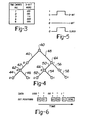
- FIGURE 3 is an example of words in an associative memory with three bit tags.
- the multiple match algorithm uses the content of these tags to extract the individual words by scanning the three bit portions in succession. Each time an "X" is sensed, a subset of matched words, i.e. words having "0" in this position, can be isolated.
- the algorithm is independent of the memory size and requires only 2m-1 read cycles to retrieve m words.
- each Sender can be treated as a word in an associative memory; successive sensings of the bit positions will be serial transmissions. Subsets of Senders can be isolated, in a like manner, through testing the transmission results.
- Such a multiple access organization called “Decentralized Priority Access” was suggested and developed by G. A. Kotyuzhanski, L. B. Nisnevich and G. G. Stetsyura “Decentralized Priority Control in a Single Channel Data Transmission System” Teknicheskaya Kibernetika No. 2, 1971, by L. B. Nisnevich and G. G. Stetsyura, Decentralized Priority Control in Integral Communication Systems, Automation and Remote Control", Vol. 33, No. 4, pp.
- the content induced transaction overlap communication system uses this algorithm in a different way. Instead of resolving channel access priority, the algorithm is applied to the acquisition of data. In the content induced transaction overlap communication system, the collection of data words is transmitted concurrently. The information content of the individual data words is then resolved gradually from the overlapping transactions in the course of the transmission. The transmission is in fact a decentralized preorder traversal of the binary tree representing the data word collection.
- This technique achieves desirable improvements in a multiple-access channel communication system in several areas, it improves average throughput and stability while decreasing delays. Additionally this technique has other properties which provide greater flexibility to transmission control.
- Some of the features of the content induced transaction overlap communication system are dynamic to varying numbers of users, immediate priority for emergency messages, content based data selection, elimination of transmission of duplicate information, no channel lock-up in burst mode, and fast recovery from overload.
- FIGURE 4 To estimate the redundancy of the sequenced data words, consider their binary tree representation illustrated in FIGURE 4.
- the branches of the tree are labeled with 0's and 1's so that the set of paths from the root to the terminal nodes represents the word collection. If order is not considered we will see that the set of branches in the tree's preorder traversal, with a relatively small amount of additional information, can be used to obtain the entire collection of words.
- the tree contains 10 branches, branches 40 through 58 which means that the information content of our collection is approximately 10 bits rather than 15.
- the preorder traversal in itself is insufficient, in general, to reconstruct the binary tree representing the collection of words.
- some additional information about the boundaries between the words must be added.
- the bifurcation points 60 through 64 of the binary tree may be indicated using the overlapping X state for conjointed branches with 0's and 1's of the preorder traversal. This corresponds to the usage of the "X" state in the above-mentioned algorithm of ordered retrieval from associative memory. Therefore, the "0's" and “1's” representing branches in the preorder traversal are mapped into the overlapped transaction symbols "0", "1" and "X".
- the number of "X's" (bifurcation points) in the transaction is equal to m-1, where m is the total number of words. This represents a general relationship between the number of nodes with two branches, i.e. the number of "X's", and the number of terminal nodes for an arbitrary binary tree. Thus, the number of branches in the binary tree is Q + (m-1).
- the number of read cycles required to extract m words from the associative memory is the sum of the number of "X's" and the number of words, i.e. (2,-,).
- the information content (I) of the collection of m r-bit words is greater than the number of bits in the preorder traversal (Q + m-1). On the other hand, it is less than the total information which can be represented by Q ternary symbols, i.e. Q log 3.
- the factor [1 - (log m/r)/r] in equation (4) is less than one when m is greater than r.
- the fundamental operation of the content induced transaction overlap communication system is the overlapped sending of the individual data bits following the analogy with multi-match resolution in associative memory discussed above.
- This representation results in the channel state "0” or "X” appearing as a finite level signal and a channel state "1" appearing as a null.
- the number of Senders in this implementation is inconsequential, but the number of distinguishable messages is limited to 2 m .
- the communication channel When the Sender has transmitted a finite level signal indicative of a zero bit, the communication channel will be in the "0" or "X" state. This Sender can continue transmission. If a Sender has transmitted a null level signal indicative of a one-bit, it must first determine the state of the communication channel before continuing transmission. When the channel state is a one bit, a null signal level, then the transmitted one bit is picked up by the Receiver and the Sender can continue its activity. However, if the channel state is a "0" bit as indicated by a finite level signal, the Receiver does not receive the transmitted null signal and the Sender recognizes the transmitted one-bit is different-from the communication channel state.
- the Sender then knows that in fact the communication channel state is an "X" state with at least one other Sender transmitting a zero-bit.
- the Sender retains its current bit position and delays further transmissions.
- This coding organizes the transmission so that the lexicographically smallest words in the transmitting collection are the first received by the Receiver.
- the channel states 0, X and 1 carry information.
- a separator symbol, such a "Z" in a bi-phase implementation is avoided in the single phase implementation of the content induced transaction overlap communication system. Therefore special protocols must be introduced to identify the word collection boundaries.
- FIGURE 6 depicts the format of the message transmitted to the Receiver 20, using the example data shown in FIGURE 3.
- the message comprises two types of information, bit position and data.
- the bit position information is used by the Receiver to reconstruct the word upon receipt.
- each Sender's Word Boundary Register 38 and Bit Position Register 34 (FIGURE 2) is loaded with the value "r" indicative of the number of bits, in the word to be transmitted.
- the transmission over the communication channel 30 begins with each of the m Senders simultaneously transmitting their higher order data bit. Those transmitting a "0"-bit, raise the signal level on the communication channel 30 by a finite value. Those transmitting a 1-bit leave the signal value on the communication channel unchanged. Each sender listens to the communication channel during this transmission.
- the Sender just transmitted a 0 or 1 and senses that the state of the channel is not the same as its transmitted bit, it will decrement only its Word Boundary Register 38 and does not transmit its next bit. This Sender however continues to listen to the communication channel and decrements it's Word Boundary Register 38 with each bit transmitted by the other Senders.
- bit competition the value which has been shifted into the Word Boundary Register is lexicographically the smallest value present in any of the Bit Position Registers of the remaining Senders.
- the Senders still needing to transmit data now compare their Bit Position and Word Boundary Registers. If the two are equal, the Sender immediately begins to transmit the next bit in its data register.
- the Senders which win the bit competition are the Senders which have the fewest bits in their data words remaining to be transmitted. There may be only one Sender winning the bit competition but in case of redundancy in the word to be transmitted, it is possible more than one sender can win the bit competition.
- the bit competition winner is the Sender or Senders which ceased transmission at the last bifurcation point on the tree. The data transmission resumes with the traversal down this branch. The Sender which won the bit competition does not resend the "1" it was sending when it terminated transmission. This is due to the fact that the Receiver 20 already knows the value of this bit. In particular, if the Sender or Senders which win the bit competition have only one more bit to send it does not send this bit since its value must be "1".
- Synchronization with the communication channel implies that the Sender is able to distinguish word boundaries and bit competitions. Once the Sender is synchronized in this manner, it may enter into data transmission on the communication channel. If the Senders are to be permitted to dynamically attach and detach themselves, it is necessary that they be able to synchronize themselves when they come on line. As no special synchronization symbol is used, synchronization can only take place by recognition of a unique data pattern, a data pattern which cannot occur during the transmission of a bucket. This unique pattern might be a series of log (r) + 1 + r bits of "1" appearing on the communication channel at the end of a data bucket. A Sender wishing to achieve synchronization uses this as a cue.
- the functions of the algorithm for the content induced transaction overlap communication systems are preferably implemented by a programmed microprocessor having adequate storage and computation capabilities, such as the 8080A Microprocessor manufactured by Intel Corporation of Santa Clara, California or any other microcomputer or comparable capabilities.
- the algorithm may be hardware implemented using commercially available integrated circuits and discrete electronic components.
- Pseudo Code is used for the program listings since it is not intended to dedicate the invention to a particular microprocessor or type of microprocessor and Pseudo Code listings are universally applicable to different types of computers and computer languages. Therefore a programmer having ordinary skill in the art would be able to translate the presented Pseudo Code program listings into actual program listings for a particular computer. Additionally a person skilled in the electronic circuit art would be able to translate the presented Pseudo Code program into a hardware implementation using commercially available integrated circuits and discrete components.
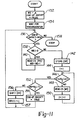
- the Sender procedure begins with initializing the Data Register 32, the Bit Position Register 34, Word Boundary Register 38 and an index register as shown in block 70.
- the index register is a pointer pointing to the data bits in the Data Register to be transmitted.
- the first decision block 72 inquires if the index "i" is less than one indicating there are no more bits remaining to be transmitted. If "i" is 0 then all the data has been transmitted and the procedure ends for that Sender as indicated by procedure termination block 74.
- the Sender keeps silent on the channel as indicated by block 82 and does not transmit the logical 1 data bit, since the transmission of a 1 bit is a null signal on the channel.
- the procedure then checks the Channel Status (CS) to determine, if another Sender transmitted a zero bit as indicated by decision block 84. If another Sender has transmitted a zero bit, the procure calls the "Wait-for-end of Word" and Perform Bit Competition subroutines, indicated by blocks 86 and 88 respectively. If the Sender wins the bit competition indicated by block 88, it then decrements its Bit Position Register 34 and Word Boundary Register 38 and proceeds to transmit the next bit in its Data Register 32.
- CS Channel Status
- the subroutine "Wait for End of Word” begins by inquiring if the content of its Word Boundary Register 38 is greater than zero as indicated by decision block 90. If it is, it then waits for the next clock cycle, decision block 92, then decrements only the Word Boundary Register 38. When the Word Boundary Register 38 is decremented to 0, the subroutine is returned to Sender procedure shown in FIGURE 7 as indicated by its procedure termination block 96.
- FIGURE 9 gives the details of the subroutine "Perform Bit Competition" which is performed by all the Senders which have not completed the transmission of their data word. This Subroutine is performed after the Sender having final access to the communication channel has completed sending its entire data word and follows the completion of the subroutine "Wait for End of Word.”
- the subroutine "Perform Bit Competition" shown on FIGURE 9 begins with setting a Watch Flag to "true” as indicated by Block 98.
- the subroutine then inquires if the Watch Flag is "true” and the pointer j to a predetermined number, log2 (r) + 1 as indicated by decision block 100. If the Watch Flag is "true” the subroutine sets a Sending Flag to "true” as indicated by block 102. If the Watch Flag is "false” the subroutine is terminated as indicated by procedure termination block 104 and returns to the Sending Procedure given on FIGURE 7. After the Sending Flag is set to "true", the subroutine inquires, decision block 106, if all the bits in the Bit Position Register 34 have been transmitted i.e.
- the subroutine keeps silent on the channel as indicated by block 114.
- the subroutine then inquires, decision block 116 if the state of the Channel Status Register 36 is a logical 0. If it is, the Sending Flag is set to false as indicated by block 118, otherwise the subroutine proceeds directly to call the subroutine Read CS (WB), block 120 which records the channel state directly into the Word Boundary Register 38.
- the subroutine compares, the content of the Word Boundary Register 38 with the content of the Bit Position Register 34 as indicated by decision block 124. If they are equal, the Watch Flag is set to "false", as indicated by block 126, and the subroutine is terminated as previously described. Otherwise the subroutine recalls the subroutine "Wait for End of Word” as indicated by block 86.
- the setting of the Watch Flag to false in response to the content of the Word Boundary Register 38 being the same as the content of the Bit Position Register 34 signifies that the remaining bits in the Senders Data Register 32 is lexicographically the smallest remaining to be transmitted and that transmission of these remaining bits can proceed.
- FIGURE 10 gives the details of the subroutine "Read Channel Status into Word Boundary Register” (READ CS (WB)) performed during the "Perform Bit Competition” subroutine.
- READ CS Word Boundary Register
- the subroutine "Read Channel Status into Word Boundary Register" as shown on FIGURE 10 begins by shifting the bits in the Word Boundary Register by one bit as indicated by block 126 then reading the state of the channel into the first bit position as indicated by block 128. The subroutine then returns to the Perform Bit Competition subroutine of FIGURE 10 as indicated by procedure termination block 130.
- the Receiver procedure begins by initializing a Receiver Word Boundary Register and setting an End-of-Bucket Flag to "false" as indicated in block 132.
- the Receiver then waits for synchronization as indicated by block 134.
- the synchronization signal is a series of all 1s. This is the null transmitted by the Senders during the Bit Competition subroutine after the last data bit in the current bucket has been sent.
- the procedure then inquires, decision block 136, if the End-of-Bucket Flag is false. If it is, the program proceeds to inquire, decision block 138, if the Receiver's Word Boundary Register is empty.
- the Receiver' s Word Boundary Register is not empty, the channel status is read into the Receiver's Data Register and the Receiver's Word Boundary Register is decremented as indicated by block 140.
- the program then proceeds to repeatedly analyze the content of the Receiver's Word Boundary Register and store the channel state in the Receiver's Data Register until the Receiver's Word Boundary Register is decremented to zero indicating the entire data word has been received.
- the Receiver then stores the data word read into the Receiver's Data Register as indicated by block 142.
- the receiver monitors the bit competition performed by the Senders by first setting the pointer "I" in the Receiver's Word Boundary Register to 1 as indicated by block 142.
- decision block 146 if the bit competition is completed, i.e. I > logg (r) + 1. If the bit competition is still going on the Receiver reads the channel status into the Receiver's Word Boundary Register and increments "I" as indicated by blocks 148 and 150, respectively. When the bit competition is completed, indicated by I > log 2 (r) + 1 in decision block 146, the Receiver then inquires, block 152, if the content of the Receiver's Word Boundary Register are all 1's indicating the End of the Bucket. If this is so, the End-of-Bucket Flag is set to "true" and the procedure stops as indicated by procedure termination block 158.
- the content of the Receiver's Data Register is shift right a number of bits corresponding to the number stored in the Receiver's Word Boundary Register, as indicated by block 156.
- the data is then shifted left one bit and the low order bit in the register is set to one as indicated by block 157.
- the procedure then returns to record the next data bit sequence transmitted by the Senders as previously discussed. This procedure is repeated until all of the Senders have completed sending their data words and the End-of-Bucket code is detected in decision block 152.
Landscapes
- Engineering & Computer Science (AREA)
- Computer Networks & Wireless Communication (AREA)
- Signal Processing (AREA)
- Communication Control (AREA)
- Small-Scale Networks (AREA)
Claims (15)
Applications Claiming Priority (2)
| Application Number | Priority Date | Filing Date | Title |
|---|---|---|---|
| US439012 | 1982-11-03 | ||
| US06/439,012 US4493074A (en) | 1982-11-03 | 1982-11-03 | Content induced transaction overlap communication system |
Publications (3)
| Publication Number | Publication Date |
|---|---|
| EP0108672A2 EP0108672A2 (fr) | 1984-05-16 |
| EP0108672A3 EP0108672A3 (en) | 1986-01-08 |
| EP0108672B1 true EP0108672B1 (fr) | 1989-03-15 |
Family
ID=23742926
Family Applications (1)
| Application Number | Title | Priority Date | Filing Date |
|---|---|---|---|
| EP83402052A Expired EP0108672B1 (fr) | 1982-11-03 | 1983-10-21 | Système de communication avec déroulement à recouvrement induit par le continu |
Country Status (5)
| Country | Link |
|---|---|
| US (1) | US4493074A (fr) |
| EP (1) | EP0108672B1 (fr) |
| JP (1) | JPS5997253A (fr) |
| CA (1) | CA1199385A (fr) |
| DE (1) | DE3379444D1 (fr) |
Families Citing this family (14)
| Publication number | Priority date | Publication date | Assignee | Title |
|---|---|---|---|---|
| SE465347B (sv) * | 1984-04-25 | 1991-08-26 | Matsushita Electric Works Ltd | Bildsaendningssystem foer sampling och komprimering av bilddata i ett tv-bildfaelt |
| US4598411A (en) * | 1984-07-17 | 1986-07-01 | Allied Corporation | On-the-fly data compression system |
| US4855997A (en) * | 1987-12-21 | 1989-08-08 | Allied-Signal, Inc. | Priority queuing technique for content induced transaction overlap (CITO) communication system |
| WO1989009966A2 (fr) * | 1988-04-08 | 1989-10-19 | Allied-Signal Inc. | Systeme informatise avec memoire associative decentralisee |
| US5146456A (en) * | 1988-04-08 | 1992-09-08 | Allied-Signal Inc. | Computer system with distributed content-addressable memory modules compatible with cito transmission |
| US5255380A (en) * | 1988-04-08 | 1993-10-19 | Allied-Signal Inc. | Computer system with distributed RAM memory modules designed for CITO transmission |
| US4868814A (en) * | 1988-07-22 | 1989-09-19 | Allied-Signal Inc. | Multilevel concurrent communications architecture for multiprocessor computer systems |
| US4959843A (en) * | 1989-05-08 | 1990-09-25 | Allied-Signal Inc. | Content induced transaction overlap (CITO) block transmitter |
| US5095481A (en) * | 1989-05-12 | 1992-03-10 | Allied-Signal Inc. | Technique for active synchronization of the content induced transaction overlap (CITO) communication channel |
| US5915054A (en) * | 1992-03-05 | 1999-06-22 | Fuji Xerox Co., Ltd. | Star coupler for an optical communication network |
| US5369755A (en) * | 1992-09-08 | 1994-11-29 | Alliedsignal Inc. | Computer communication bus system using multiple content induced transaction overlap (CITO) communication channels |
| US6222851B1 (en) * | 1998-05-29 | 2001-04-24 | 3Com Corporation | Adaptive tree-based contention resolution media access control protocol |
| DE19960967A1 (de) * | 1999-12-17 | 2001-07-05 | Tenovis Gmbh & Co Kg | Verfahren zur Steuerung von Zugriffswettbewerben für an einen Bus angeschlossene Stationen |
| CN102484533B (zh) | 2009-10-29 | 2015-09-02 | 惠普发展公司,有限责任合伙企业 | 光学数据总线和方法 |
Family Cites Families (14)
| Publication number | Priority date | Publication date | Assignee | Title |
|---|---|---|---|---|
| US3752921A (en) * | 1970-11-04 | 1973-08-14 | Ibm | Distinct complex signals formed by plural clipping transformations of superposed isochronal pulse code sequences |
| US4099028A (en) * | 1977-04-21 | 1978-07-04 | Hughes Aircraft Company | Asynchronous multiplexer-demultiplexer |
| US4161786A (en) * | 1978-02-27 | 1979-07-17 | The Mitre Corporation | Digital bus communications system |
| US4199661A (en) * | 1978-05-05 | 1980-04-22 | Control Data Corporation | Method and apparatus for eliminating conflicts on a communication channel |
| US4177357A (en) * | 1978-07-03 | 1979-12-04 | The United States Of America As Represented By The Secretary Of The Navy | Spatially distributed analog time division multiplexer |
| US4199662A (en) * | 1978-07-17 | 1980-04-22 | Lowe Charles S Jr | Hybrid control of time division multiplexing |
| US4199663A (en) * | 1978-11-06 | 1980-04-22 | The Boeing Company | Autonomous terminal data communications system |
| US4232294A (en) * | 1979-04-30 | 1980-11-04 | Control Data Corporation | Method and apparatus for rotating priorities between stations sharing a communication channel |
| US4292623A (en) * | 1979-06-29 | 1981-09-29 | International Business Machines Corporation | Port logic for a communication bus system |
| JPS56164428A (en) * | 1980-05-20 | 1981-12-17 | Nippon Telegr & Teleph Corp <Ntt> | Data transfer controlling system |
| US4337465A (en) * | 1980-09-25 | 1982-06-29 | Burroughs Corporation | Line driver circuit for a local area contention network |
| JPS5787645A (en) * | 1980-11-20 | 1982-06-01 | Ricoh Co Ltd | Priority control system |
| US4408325A (en) * | 1980-11-28 | 1983-10-04 | Northern Telecom Limited | Transmitting additional signals using violations of a redundant code used for transmitting digital signals |
| US4434421A (en) * | 1981-11-18 | 1984-02-28 | General Electric Company | Method for digital data transmission with bit-echoed arbitration |
-
1982
- 1982-11-03 US US06/439,012 patent/US4493074A/en not_active Expired - Lifetime
-
1983
- 1983-09-26 CA CA000437591A patent/CA1199385A/fr not_active Expired
- 1983-10-21 DE DE8383402052T patent/DE3379444D1/de not_active Expired
- 1983-10-21 EP EP83402052A patent/EP0108672B1/fr not_active Expired
- 1983-11-02 JP JP58204997A patent/JPS5997253A/ja active Granted
Also Published As
| Publication number | Publication date |
|---|---|
| EP0108672A2 (fr) | 1984-05-16 |
| CA1199385A (fr) | 1986-01-14 |
| JPS5997253A (ja) | 1984-06-05 |
| EP0108672A3 (en) | 1986-01-08 |
| US4493074A (en) | 1985-01-08 |
| JPH0460381B2 (fr) | 1992-09-25 |
| DE3379444D1 (en) | 1989-04-20 |
Similar Documents
| Publication | Publication Date | Title |
|---|---|---|
| EP0108672B1 (fr) | Système de communication avec déroulement à recouvrement induit par le continu | |
| US4855997A (en) | Priority queuing technique for content induced transaction overlap (CITO) communication system | |
| CA1242799A (fr) | Systeme de compression de donnees a la volee | |
| CA1079829A (fr) | Technique d'appel multipoint | |
| EP0180448B1 (fr) | Méthode pour transmettre simultanément des données isochrones et non isochrones dans un réseau local | |
| US4332027A (en) | Local area contention network data communication system | |
| US5781129A (en) | Adaptive encoder circuit for multiple data channels and method of encoding | |
| US5592518A (en) | Parallel frame synchronizer for detecting forward-ordered/reverse-ordered, inverted/non-inverted data | |
| US4337465A (en) | Line driver circuit for a local area contention network | |
| CA1106503A (fr) | Appareil de transition entre un reseau et une liaison | |
| EP0777876A1 (fr) | Procede et appareil de transmission synchronisee de donnees entre une carte reseau et des voies de transmission multiples | |
| IL44863A (en) | Detector of literary phrases | |
| JPS58108844A (ja) | デイジタル・デ−タ通信方法 | |
| EP0694237A1 (fr) | Systeme de transfert de donnees | |
| US4750150A (en) | I/O scanner for an industrial control | |
| EP0130206A1 (fr) | Procede et dispositif permettant de resoudre un conflit d'utilisation d'un bus. | |
| US4114138A (en) | Selective calling circuit | |
| NL8702394A (nl) | Interface voor een verbindingsnetwerk tussen afzonderlijke stations enerzijds en een voor het berichtenverkeer tussen deze stations gebruikt fysiek medium anderzijds. | |
| US4823305A (en) | Serial data direct memory access system | |
| US4400811A (en) | Detecting accurrences of redundant digital codewords | |
| US5369755A (en) | Computer communication bus system using multiple content induced transaction overlap (CITO) communication channels | |
| US4065639A (en) | Synchronous transmission control system | |
| CN87106178A (zh) | 数据通信方法和设备 | |
| US4899143A (en) | High capacity communication system over collision-type channels | |
| JPH0143499B2 (fr) |
Legal Events
| Date | Code | Title | Description |
|---|---|---|---|
| PUAI | Public reference made under article 153(3) epc to a published international application that has entered the european phase |
Free format text: ORIGINAL CODE: 0009012 |
|
| AK | Designated contracting states |
Designated state(s): DE FR GB IT |
|
| PUAL | Search report despatched |
Free format text: ORIGINAL CODE: 0009013 |
|
| AK | Designated contracting states |
Designated state(s): DE FR GB IT |
|
| 17P | Request for examination filed |
Effective date: 19860613 |
|
| 17Q | First examination report despatched |
Effective date: 19871120 |
|
| RAP1 | Party data changed (applicant data changed or rights of an application transferred) |
Owner name: ALLIED-SIGNAL INC. |
|
| GRAA | (expected) grant |
Free format text: ORIGINAL CODE: 0009210 |
|
| AK | Designated contracting states |
Kind code of ref document: B1 Designated state(s): DE FR GB IT |
|
| ITF | It: translation for a ep patent filed | ||
| REF | Corresponds to: |
Ref document number: 3379444 Country of ref document: DE Date of ref document: 19890420 |
|
| ET | Fr: translation filed | ||
| PLBE | No opposition filed within time limit |
Free format text: ORIGINAL CODE: 0009261 |
|
| STAA | Information on the status of an ep patent application or granted ep patent |
Free format text: STATUS: NO OPPOSITION FILED WITHIN TIME LIMIT |
|
| 26N | No opposition filed | ||
| PGFP | Annual fee paid to national office [announced via postgrant information from national office to epo] |
Ref country code: FR Payment date: 19911007 Year of fee payment: 9 |
|
| PGFP | Annual fee paid to national office [announced via postgrant information from national office to epo] |
Ref country code: GB Payment date: 19911011 Year of fee payment: 9 |
|
| ITTA | It: last paid annual fee | ||
| PGFP | Annual fee paid to national office [announced via postgrant information from national office to epo] |
Ref country code: DE Payment date: 19911129 Year of fee payment: 9 |
|
| PG25 | Lapsed in a contracting state [announced via postgrant information from national office to epo] |
Ref country code: GB Effective date: 19921021 |
|
| GBPC | Gb: european patent ceased through non-payment of renewal fee |
Effective date: 19921021 |
|
| PG25 | Lapsed in a contracting state [announced via postgrant information from national office to epo] |
Ref country code: FR Effective date: 19930630 |
|
| PG25 | Lapsed in a contracting state [announced via postgrant information from national office to epo] |
Ref country code: DE Effective date: 19930701 |
|
| REG | Reference to a national code |
Ref country code: FR Ref legal event code: ST |