EP0108824A1 - Vorrichtung zum elektrischen Widerstands-Längsnaht-Quetschnahtschweissen - Google Patents
Vorrichtung zum elektrischen Widerstands-Längsnaht-Quetschnahtschweissen Download PDFInfo
- Publication number
- EP0108824A1 EP0108824A1 EP82110503A EP82110503A EP0108824A1 EP 0108824 A1 EP0108824 A1 EP 0108824A1 EP 82110503 A EP82110503 A EP 82110503A EP 82110503 A EP82110503 A EP 82110503A EP 0108824 A1 EP0108824 A1 EP 0108824A1
- Authority
- EP
- European Patent Office
- Prior art keywords
- frame edges
- welding point
- welding
- rail
- overlap
- Prior art date
- Legal status (The legal status is an assumption and is not a legal conclusion. Google has not performed a legal analysis and makes no representation as to the accuracy of the status listed.)
- Granted
Links
Images


Classifications
-
- B—PERFORMING OPERATIONS; TRANSPORTING
- B23—MACHINE TOOLS; METAL-WORKING NOT OTHERWISE PROVIDED FOR
- B23K—SOLDERING OR UNSOLDERING; WELDING; CLADDING OR PLATING BY SOLDERING OR WELDING; CUTTING BY APPLYING HEAT LOCALLY, e.g. FLAME CUTTING; WORKING BY LASER BEAM
- B23K11/00—Resistance welding; Severing by resistance heating
- B23K11/06—Resistance welding; Severing by resistance heating using roller electrodes
- B23K11/061—Resistance welding; Severing by resistance heating using roller electrodes for welding rectilinear seams
- B23K11/062—Resistance welding; Severing by resistance heating using roller electrodes for welding rectilinear seams for welding longitudinal seams of tubes
- B23K11/063—Lap welding
Definitions
- the invention relates to a device for the semiautomatic or fully automatic electrical resistance longitudinal seam squeeze seam welding of can bodies from rolled, overlapping sheet metal blanks with frames, with a guide device arranged in front of the welding point for fixing the overlap width of the frame edges with spring-loaded guide elements through which the frame edges can be pressed against the groove bases of a Z-rail at the inlet to the welding point, and with a calibration ring arranged in the area of the welding point, with a design of the guide device such that the overlap width of the frame edges at the welding point is at most six times the can wall thickness, and with one Roll removable, guided over electrode rolls, formed as flat wire electrodes with a width lying over the overlap width of the frame edges at the welding point.
- the object of the invention is to avoid the disadvantages mentioned while at the same time maintaining an at least equally good functionality of the device.
- the aim here is in particular an easy to manufacture and adjustable Z-rail and a simpler manufacture and adjustment of the bearings for the electrode rollers.
- the invention accordingly consists in a device of the type mentioned above that the groove bases of the Z-rail run parallel in the sense of a constant overlap of the frame edges, and that the axes of the electrode rollers lie in the plane perpendicular to the welding direction.
- the invention also results in the distribution that the frames already take on a shape more approximated to the cylindrical shape during feeding along the Z-rail than in the known device, in which there is a greater tapering of the frames in this area. Furthermore, the invention has the advantage that the frames are fed more smoothly, since an overlap that is not too wide is not first generated and then this must be reduced again; the annoying transition from increasing to decreasing overlap is thus avoided. Finally, the shape of the Z-rail provided according to the invention facilitates the regrinding of worn Z-rails for reuse in welding with a large overlap.
- FIG. 1 shows a section of an electrical resistance longitudinal seam squeeze welding machine 1 with a lower, fixed welding arm 3 and an upper, pivotable welding arm 5. At the ends of these welding arms 3, 5 there is a lower electrode roller 7 and an upper electrode roller 9. A flat wire electrode 11, shown in FIG. 2, is guided over these electrode rollers 7, 9, approximately one has rectangular cross section.
- the electrode rollers 7 and 9 are provided with corresponding roller journals 15 and 16, which are arranged in corresponding fork-shaped ends of the upper and lower welding arms 3 and 5, respectively.
- the electrode rollers 7 and 9 each have an annular groove 18 for receiving the flat wire electrode 11.
- the flat wire electrode 11, as can be seen from FIG. 2, protrudes correspondingly over the profile of the electrode rollers 7 and 9, but is otherwise well-fed in the annular groove 18.
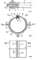
- FIGS. 4 shows, in addition to a Z-rail 13, a frame 20 with the frame edges 21 and 22, which frame edges 21 and 22 are inserted in the upper and lower grooves 26 and 27 and correspondingly by means of laterally arranged guide jaws 32 to 34 an upper groove bottom 29 of the groove 26 and a lower groove bottom 30 of the groove 27 are pressed.
- Adjustable springs 36 to 38 supported at one end on the welding machine and arranged in pairs, press the guide jaws 32 to 34 with the appropriate force onto the frame 20, with a view to precise guidance of the frame edges 21 and 22 and in particular their exact overlap is of crucial importance for successful welding.
- the two grooves 26 and 27 or groove bases 29 and 30 run parallel to one another in the sense of a constant overlap of the frame edges 21 and 22.
- This constant overlap in the direction of the welding process enables a weld metal to be welded lengthways to produce the weld seam of practically constant overlap.
- the frame 20 is pressed by the guide jaws 32 to 34 into the groove bases 29 and 30, the pressure being able to be adapted to the circumstances by appropriately tensioning or relaxing the springs 36 to 38.
- Fig. 6 the - adjustable - stroke h is shown. Without these guide jaws 32 to 34, a good fit of the frame edges 21 and 22 in the Z-rail 13 cannot be guaranteed.
- the pressing pressure of the guide jaws 32 to 34 must of course not be too high, since otherwise the frame edges 21, 22 on the Z-rail 13 can be damaged and / or they oppose excessive movement of the frame 20.
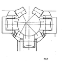
- the three guide jaws 32 to 34 are adjoined - at the level of the welding point - by a calibration ring comprising rotatable, fixedly arranged but adjustable calibration rollers 40, as shown in FIG. 7 and indicated in FIG. 6.
- a number of tightly opened resilient centering rings could also be provided.
- the frame edges 21 and 22 of the frame 20 to be welded are introduced overlapping between the two sections of the flat wire electrode 11, the area in which the two frame edges 21 and 22 of the frame 20 overlap are narrower than the width of the sections of the flat wire electrode 11.
- the degree of overlap with respect to the width of the flat wire electrode 11 can be defined in different ways, but the overlap should in any case be narrower than the width of the flat wire electrode 11.
- the overlap is preferably in the middle of the sections of the flat wire electrode 11, the width of the overlap corresponding approximately to half the width of the sections of the flat wire electrode 11.
Landscapes
- Engineering & Computer Science (AREA)
- Mechanical Engineering (AREA)
- Resistance Welding (AREA)
- Butt Welding And Welding Of Specific Article (AREA)
- Arc Welding In General (AREA)
Abstract
Description
- Die Erfindung bezieht sich auf eine Vorrichtung zum halb- oder vollautomatischen elektrischen Widerstands-Längsnaht-QuetschnahtschweiBen von Dosenkörpern aus zu Zargen gerollten, sich überlappenden Blechzuschnitten, mit einer vor der Schweißstelle angeordneten Führungseinrichtung zum Festlegen der Überlappungsbreite der Zargenränder mit gefederten Führungselementen, durch die die Zargenränder beim Zulauf zur Schweißstelle gegen die Nutgründe einer Z-Schiene andrückbar sind, und mit einem im Bereich der Schweißstelle angeordneten Kalibrierkranz, mit einer derartigen Ausbildung der Führungseinrichtung, daß die Überlappungsbreite der Zargenränder an der Schweißstelle höchstens das Sechsfache der Dosenwandstärke beträgt, und mit von einer Rolle abziehbaren, über Elektrodenrollen geführten, als Flachdrahtelektroden mit einer über der Überlappungsbreite der Zargenränder an der Schweißstelle liegenden Breite ausgebildeten Drahtelektroden.
- Bei einer bekannten Vorrichtung dieser Art (DE-PS 25 59 671) ist eine derartige Ausbildung der Z-Schiene vorgesehen, daß die Nutgründe der Z-Schiene in Richtung auf die Schweißstelle zu im Sinne einer stetig abnehmenden Überlappung der Zargenränder zusammenlaufen, und eine derartige Schrägstellung der Achsen der Elektrodenrollen gegenüber der zur Schweißrichtung senkrechten Ebene vorgesehen, daß die Zargenränder dadurch übereinander geschoben werden. Nachteilig an dieser bekannten Vorrichtung ist, daß das Herstellen einer derart ausgebildeten Z-Schiene schwierig und kostenspielig ist, und daß eine derartig ausgebildete Z-Schiene nur mühsam an der Vorrichtung richtig einzurichten ist. Dieser Nachteil ist besonders störend, wenn Z-Schienen mit unter vorgegebenen Winkeln zusammenlaufenden Nutgründen bestimmten Schweißnahtlängen, also Zargenhöhen, und Schweißgeschwindigkeiten zugeordnet sind, so daß bei Umstellungen der Fertigung jeweils die Z-Schiene ausgetauscht werden muß. Ferner ist es bei der bekannten Vorrichtung nachteilig, daß zum Erzielen der richtigen Schrägstellung der Achsen der Elektrodenrollen eine hohe Fertigungsgenauigkeit und eine genaue Kontrolle notwendig ist.
- Aufgabe der Erfindung ist es, die genannten Nachteile bei gleichzeitiger Beibehaltung einer mindestens gleichguten Funktionsfähigkeit der Vorrichtung zu vermeiden. Hierbei wird insbesondere eine einfach herstellbare und einstellbare Z-Schiene und eine einfachere Herstellung und Einstellung der Lagerungen für die Elektrodenrollen angestrebt.
- Die Erfindung besteht demgemäß bei einer Vorrichtung der eingangs genannten Art darin, daß die Nutgründe der Z-Schiene im Sinne einer gleichbleibenden Überlappung der Zargenränder parallel verlaufen, und daß die Achsen der Elektrodenrollen in der zur Schweißrichtung senkrechten Ebene liegen.
- Überraschenderweise hat sich herausgestellt, daß weder die bisher für erforderlich erachtete Ausbildung der Z-Schiene noch die ebenfalls bisher für erforderlich erachtete Schrägstellung der Elektrodenrollen notwendig ist, um eine befriedigende Funktionsfähigkeit der Vorrichtung im Hinblick auf das Schweißen von Dosenkörpern zu erzielen. Mit der Erfindung ergibt sich auch der Verteil, daß die Zargen schon während des Zuführens entlang der Z-Schiene eine der Zylinderform mehr angenäherte Form annehmen als bei der bekannten Vorrichtung, bei der sich in diesem Bereich eine stärkere Kegeligkeit der Zargen ergibt. Weiter bringt die Erfindung den Vorteil mit sich, daß die Zargen ruhiger zugeführt werden, da nicht zunächst eine zu breite Überlappung erzeugt und diese dann wieder verringert werden muß; es wird also der störende Übergang von zunehmender auf abnehmende Überlappung vermieden. Schließlich erleichtert die erfindungsgemäß vorgesehene Form der Z-Schiene das Nachschleifen verschlissener Z-Schienen zur Wiederverwendung bei einem Schweißen mit größerer Überlappung.
- Eine vorteilhafte Ausgestaltung der Vorrichtung nach der Erfindung ist in dem Patentanspruch 2 angegeben.
- Ausgestaltungen der Erfindung sind in der Zeichnung dargestellt, und zwar zeigt
- Fig. 1 einen Ausschnitt aus einer elektrischen Widerstands-Längsnaht-Quetschnahtschweißmaschine mit einem Teil des Maschinengestelles und den Schweißarmen mit den entsprechenden Elektrodenrollen in Seitenansicht,
- Fig. 2 eine vergrößerte Ansicht der Elektrodenrollen mit eingeführter Zarge in Schweißrichtung gesehen,
- Fig. 3 eine Ansicht auf die Elektrodenrollen gemäß Fig. 2 von oben,
- Fig. 4 einen Schnitt durch eine Z-Schiene mit in diese eingeführter Zarge nach Schnittlinie IV-IV der Fig. 5,
- Fig. 5 einen Schnitt durch die Z-Schiene nach Schnittlinie V-V der Fig. 4,
- Fig. 6 einen Schnitt durch die Anordnung nach Fig. 4 gemäß Schnittlinie VI-VI der Fig. 4 und
- Fig. 7 eine Ansicht eines in der Schweißebene senkrecht zur Bewegungsrichtung der Zarge wirkenden Kalibrierkranzes.
- In Fig. 1 ist ein Ausschnitt einer elektrischen Widerstands-Längsnaht-Quetschnahtschweißmaschine 1 schematisch dargestellt mit einem unteren, festen Schweißarm 3 und einem oberen, schwenkbaren Schweißarm 5. An den Enden dieser Schweißarme 3, 5 befinden sich eine untere Elektrodenrolle 7 und eine obere Elektrodenrolle 9. Über diese Elektrodenrollen 7, 9 ist eine Flachdrahtelektrode 11, in Fig. 2 dargestellt, gefuhrt, die einen etwa rechteckförmigen Querschnitt aufweist.
- Die Elektrodenrollen 7 und 9 sind mit entsprechenden Rollenzapfen 15 bzw. 16 versehen, welche in entsprechenden gabelförmigen Enden des oberen bzw. unteren Schweißarmes 3 bzw. 5 angeordnet sind. Die Elektrodenrollen 7 und 9 weisen je eine Ringnut 18 zur Aufnahme der Flachdrahtelektrode 11 auf. Die Flachdrahtelektrode 11 steht, wie aus Fig. 2 ersichtlich, entsprechend über das Profil der Elektrodenrollen 7 und 9 vor, liegt aber im übrigen satt in der Ringnut 18.
- In Fig. 4 ist außer einer Z-Schiene 13 auch eine Zarge 20 mit den Zargenrändern 21 und 22 dargestellt, welche Zargenränder 21 und 22 in der oberen bzw. unteren Nut 26 bzw. 27 eingeführt und mittels seitlich angeordneter Führungsbacken 32 bis 34 entsprechend auf einen oberen Nutengrund 29 der Nut 26 und einen unteren Nutengrund 30 der Nut 27 gepreßt werden. Einstellbare Federn 36 bis 38, am einen Ende an der Schweißmaschine abgestützt und je paarweise angeordnet, drücken die Führungsbacken 32 bis 34 mit der entsprechenden Kraft auf die Zarge 20, was im Hinblick auf eine genaue Führung der Zargenränder 21 und 22 und insbesondere deren genaue Überlappung von maßgebender Bedeutung für ein erfolgreiches Schweißen ist. Wie aus den Fig. 5 und 6 hervorgeht, verlaufen die beiden Nuten 26 und 27 bzw. Nutengründe 29 und 30 parallel zueinander im Sinne einer gleichbleibenden Überlappung der Zargenränder 21 und 22. Diese in Richtung des Schweißvorganges gleichbleibende Überlappung ermöglicht es, ein Schweißgut mit längs der Schweißnaht praktisch konstanter Überlappung herzustellen.
- Im gleichen Sinne wirken auch die in Fig. 2 dargestellten Elektrodenrollen 7 und 9, deren Achsen in der zur Schweißrichtung senkrechten Ebene liegen.
- In diesem Sinne hat es sich als vorteilhaft erwiesen, die Überlappung der Zargenränder 21 und 22 an der Schweißstelle drei- bis sechsmal der Blechdicke zu wählen, während die Breite der Flachdrahtelektrode 11 entsprechend zwei- bis dreimal der Überlappungsbreite gewählt sein kann.
- Um die gleichbleibende Überlappung der Zargenränder .21, 22 zu sichern, wird die Zarge 20 durch die Führungsbacken 32 bis 34 in die Nutengründe 29 und 30 gepreßt, wobei der Preßdruck durch entsprechendes Spannen oder Entspannen der Federn 36 bis 38 den Umständen angepaßt werden kann. In Fig. 6 ist der - einstellbare - Hub h dargestellt. Ohne diese Führungsbacken 32 bis 34 kann ein gutes Anliegen der Zargenränder 21 und 22 in der Z-Schiene 13 nicht garantiert werden. Der Preßdruck der Führungsbacken 32 bis 34 darf natürlich nicht zu hoch sein, da sonst die Zargenränder 21, 22 an der Z-Schiene 13 beschädigt werden können und/oder sie dem Fortbewegen der Zarge 20 einen zu großen Widerstand entgegensetzen. Den drei Führungsbacken 32 bis 34 schließt sich - auf der Höhe der Schweißstelle - ein Kalibrierkranz aus drehbaren, fest angeordneten, aber einstellbaren Kalibrierwalzen 40 an, wie diese in Fig. 7 dargestellt und in Fig. 6 angedeutet sind. Anstelle der einfacheren Führungsbacken 32 bis 34 könnten auch eine Anzahl eng aufgeschlossener federnder Zentrierkränze vorgesehen werden.
- Die zu verschweißenden Zargenränder 21 und 22 der Zarge 20 werden überlappend zwischen die beiden Abschnitte der Flachdrahtelektrode 11 eingeführt, wobei der Bereich, in dem sich die beiden Zargenränder 21 und 22 der Zarge 20 überlappen, schmaler ist als die Breite der Abschnitte der Flachdrahtelektrode 11. Das Maß der Überlappung bezüglich den Breite der Flachdrahtelektrode 11 kann verschieden festgelegt werden, wobei jedoch die Überlappung jedenfalls schmaler als die Breite der Flachdrahtelektrode 11 werden soll. Vorzugsweise liegt die Überlappung in der Mitte der Abschnitte der Flachdrahtelektrode 11, wobei die Breite der Überlappung etwa der halben Breite der Abschnitte der Flachdrahtelektrode 11 entspricht.
Claims (2)
Priority Applications (13)
| Application Number | Priority Date | Filing Date | Title |
|---|---|---|---|
| EP82110503A EP0108824B1 (de) | 1982-11-13 | 1982-11-13 | Vorrichtung zum elektrischen Widerstands-Längsnaht-Quetschnahtschweissen |
| AT82110503T ATE30393T1 (de) | 1982-11-13 | 1982-11-13 | Vorrichtung zum elektrischen widerstandsl|ngsnaht-quetschnahtschweissen. |
| DE8282110503T DE3277524D1 (en) | 1982-11-13 | 1982-11-13 | Appliance for the electric resistance welding of longitudinal seams using seam squeezing |
| CA000440907A CA1211512A (en) | 1982-11-13 | 1983-11-10 | Device for electrical resistance welding of long pinched seams |
| AR294781A AR230581A1 (es) | 1982-11-13 | 1983-11-11 | Dispositivo para la soldadura electrica a resistencia de costuras longitudinales presionadas |
| ES527187A ES527187A0 (es) | 1982-11-13 | 1983-11-11 | Dispositivo para la soldadura por resistencia de costura longitudinal y transversal electrica, semi- o totalmente automatica, de cuerpos de bote |
| JP58503645A JPH0655356B2 (ja) | 1982-11-13 | 1983-11-12 | 電気抵抗縦継目シーム溶接装置 |
| US06/631,553 US4568812A (en) | 1982-11-13 | 1983-11-12 | Device for electric longitudinal-seam mash resistance welding |
| BR8307608A BR8307608A (pt) | 1982-11-13 | 1983-11-12 | Dispositivo para a soldagem forte,eletrica,por resistencia,da costura longitudinal costura de esmagamento |
| PCT/DE1983/000187 WO1984001914A1 (fr) | 1982-11-13 | 1983-11-12 | Installation de soudage longitudinal electrique continu en ligne par ecrasement et resistance |
| GR72961A GR79386B (de) | 1982-11-13 | 1983-11-14 | |
| DK325284A DK167106B1 (da) | 1982-11-13 | 1984-07-03 | Apparat til elektrisk modstandssvejsning af en langsgaaende soem paa daaselegemer |
| NO842770A NO166521C (no) | 1982-11-13 | 1984-07-06 | Innretning for elektrisk motstandssveising av langsgaaendesoemmer og klemsoemmer. |
Applications Claiming Priority (1)
| Application Number | Priority Date | Filing Date | Title |
|---|---|---|---|
| EP82110503A EP0108824B1 (de) | 1982-11-13 | 1982-11-13 | Vorrichtung zum elektrischen Widerstands-Längsnaht-Quetschnahtschweissen |
Publications (2)
| Publication Number | Publication Date |
|---|---|
| EP0108824A1 true EP0108824A1 (de) | 1984-05-23 |
| EP0108824B1 EP0108824B1 (de) | 1987-10-28 |
Family
ID=8189335
Family Applications (1)
| Application Number | Title | Priority Date | Filing Date |
|---|---|---|---|
| EP82110503A Expired EP0108824B1 (de) | 1982-11-13 | 1982-11-13 | Vorrichtung zum elektrischen Widerstands-Längsnaht-Quetschnahtschweissen |
Country Status (11)
| Country | Link |
|---|---|
| US (1) | US4568812A (de) |
| EP (1) | EP0108824B1 (de) |
| JP (1) | JPH0655356B2 (de) |
| AR (1) | AR230581A1 (de) |
| AT (1) | ATE30393T1 (de) |
| CA (1) | CA1211512A (de) |
| DE (1) | DE3277524D1 (de) |
| DK (1) | DK167106B1 (de) |
| ES (1) | ES527187A0 (de) |
| GR (1) | GR79386B (de) |
| WO (1) | WO1984001914A1 (de) |
Cited By (1)
| Publication number | Priority date | Publication date | Assignee | Title |
|---|---|---|---|---|
| DE3920974A1 (de) * | 1988-11-30 | 1990-05-31 | Cefin Spa | Vorrichtung zur vorkalibrierung von zylindrischen, gehaeusefoermigen elementen fuer kontinuierlich arbeitende schweissmaschinen |
Families Citing this family (6)
| Publication number | Priority date | Publication date | Assignee | Title |
|---|---|---|---|---|
| CH674327A5 (de) * | 1984-12-19 | 1990-05-31 | Elpatronic Ag | |
| GB2198674B (en) * | 1986-12-17 | 1990-01-31 | Metal Box Plc | Resistance welding apparatus |
| US4924262A (en) * | 1989-06-22 | 1990-05-08 | Xerox Corporation | Shutter calibration and document size detection |
| USRE36612E (en) * | 1995-02-23 | 2000-03-14 | Toyota Jidosha Kabushiki Kaisha | Mash seam welding process and mash seam welding apparatus |
| DE59604358D1 (de) * | 1995-08-09 | 2000-03-09 | Elpatronic Ag | Schweissverfahren für beschichtetes Blech, insbesondere Weissblech |
| CN101780593B (zh) * | 2009-11-12 | 2012-09-19 | 无锡威华电焊机制造有限公司 | 包边焊机的滚轮装置 |
Citations (4)
| Publication number | Priority date | Publication date | Assignee | Title |
|---|---|---|---|---|
| DE1050938B (de) * | 1959-02-19 | |||
| US3834010A (en) * | 1972-09-19 | 1974-09-10 | R Wolfe | Method for forming welded seam can bodies |
| FR2304434A1 (fr) * | 1975-03-19 | 1976-10-15 | Paul Opprecht | Procede de soudage electrique et machine a souder par resistance pour la mise en oeuvre du procede |
| GB2006659A (en) * | 1977-10-27 | 1979-05-10 | Opprecht Paul | Resistance welding machine for seam welding of blanks |
Family Cites Families (9)
| Publication number | Priority date | Publication date | Assignee | Title |
|---|---|---|---|---|
| CA1070086A (en) * | 1975-06-25 | 1980-01-22 | Walter J. Sakowski | Lime recovery process |
| CH614877A5 (en) * | 1976-12-17 | 1979-12-28 | Fael Sa | Resistance seam welding process and device for carrying out the process |
| JPS5426213A (en) * | 1977-07-30 | 1979-02-27 | Sumitomo Metal Ind Ltd | Additive adding method at the time of tapping |
| US4272004A (en) * | 1979-10-23 | 1981-06-09 | Sws Incorporated | Z-Bar guide apparatus |
| JPS5772781A (en) * | 1980-10-27 | 1982-05-07 | Fuji Kogyosho:Kk | Method and device for wire electrode seam welding |
| JPS57106480A (en) * | 1980-12-24 | 1982-07-02 | Fuji Kogyosho:Kk | Method and device for fully automatic resistance seam welding of thin walled can body |
| CA1177419A (en) * | 1981-02-11 | 1984-11-06 | Edward P. Spencer | Method of producing container bodies and container bodies produced thereby |
| JPS57165187A (en) * | 1981-04-02 | 1982-10-12 | Daiwa Can Co Ltd | Welding machine for can body |
| JPS57193284A (en) * | 1981-05-25 | 1982-11-27 | Daiwa Can Co Ltd | Production of welded can body |
-
1982
- 1982-11-13 EP EP82110503A patent/EP0108824B1/de not_active Expired
- 1982-11-13 AT AT82110503T patent/ATE30393T1/de not_active IP Right Cessation
- 1982-11-13 DE DE8282110503T patent/DE3277524D1/de not_active Expired
-
1983
- 1983-11-10 CA CA000440907A patent/CA1211512A/en not_active Expired
- 1983-11-11 AR AR294781A patent/AR230581A1/es active
- 1983-11-11 ES ES527187A patent/ES527187A0/es active Granted
- 1983-11-12 WO PCT/DE1983/000187 patent/WO1984001914A1/de not_active Ceased
- 1983-11-12 US US06/631,553 patent/US4568812A/en not_active Expired - Lifetime
- 1983-11-12 JP JP58503645A patent/JPH0655356B2/ja not_active Expired - Lifetime
- 1983-11-14 GR GR72961A patent/GR79386B/el unknown
-
1984
- 1984-07-03 DK DK325284A patent/DK167106B1/da not_active IP Right Cessation
Patent Citations (4)
| Publication number | Priority date | Publication date | Assignee | Title |
|---|---|---|---|---|
| DE1050938B (de) * | 1959-02-19 | |||
| US3834010A (en) * | 1972-09-19 | 1974-09-10 | R Wolfe | Method for forming welded seam can bodies |
| FR2304434A1 (fr) * | 1975-03-19 | 1976-10-15 | Paul Opprecht | Procede de soudage electrique et machine a souder par resistance pour la mise en oeuvre du procede |
| GB2006659A (en) * | 1977-10-27 | 1979-05-10 | Opprecht Paul | Resistance welding machine for seam welding of blanks |
Cited By (1)
| Publication number | Priority date | Publication date | Assignee | Title |
|---|---|---|---|---|
| DE3920974A1 (de) * | 1988-11-30 | 1990-05-31 | Cefin Spa | Vorrichtung zur vorkalibrierung von zylindrischen, gehaeusefoermigen elementen fuer kontinuierlich arbeitende schweissmaschinen |
Also Published As
| Publication number | Publication date |
|---|---|
| WO1984001914A1 (fr) | 1984-05-24 |
| AR230581A1 (es) | 1984-05-31 |
| ES8500110A1 (es) | 1984-10-01 |
| EP0108824B1 (de) | 1987-10-28 |
| US4568812A (en) | 1986-02-04 |
| JPS59502015A (ja) | 1984-12-06 |
| US4568812B1 (de) | 1989-05-30 |
| JPH0655356B2 (ja) | 1994-07-27 |
| DK325284A (da) | 1984-07-03 |
| CA1211512A (en) | 1986-09-16 |
| ES527187A0 (es) | 1984-10-01 |
| DE3277524D1 (en) | 1987-12-03 |
| GR79386B (de) | 1984-10-22 |
| DK325284D0 (da) | 1984-07-03 |
| ATE30393T1 (de) | 1987-11-15 |
| DK167106B1 (da) | 1993-08-30 |
Similar Documents
| Publication | Publication Date | Title |
|---|---|---|
| DE2559671C2 (de) | Vorrichtung zum halb- oder vollautomatischen elektrischen Widerstands- Längsnaht-Quetschnahtschweißen von Dosenkörpern | |
| EP0243795B1 (de) | Vorrichtung zum Hindurchführen gerundeter Zargen durch eine Schweisszone | |
| DE2843904C2 (de) | Vorrichtung zum Schneiden von streifenförmigen Werkstücken aus Gummi oder einem elastischen Kunststoff | |
| EP0910486A1 (de) | Verfahren und vorrichtung zum profilbiegen mit modularen biegestationen | |
| DE2207935A1 (de) | Einstellbare Halterung für eine Abstreichklinge im Inneren einer drehbaren Schablone einer Druckmaschine für Streifenmaterial | |
| EP0108824B1 (de) | Vorrichtung zum elektrischen Widerstands-Längsnaht-Quetschnahtschweissen | |
| DE2531290C3 (de) | Verfahren zum Biegen von Kettengliedern und Kettengliedbiegemaschine zur Durchführung des Verfahrens | |
| DE2642583A1 (de) | Schweissmaschine zum verbinden von bandstahlabschnitten oder -rollen | |
| DE2154438C3 (de) | Schraubennaht-Rohrwerk | |
| EP0022123B1 (de) | Elektrodenanordnung an einer Gitterschweissmaschine | |
| DE2839407A1 (de) | Widerstandsschweissmaschine zum nahtschweissen von blechen | |
| EP0349953A2 (de) | Vorrichtung zum Bearbeiten von Stangenmaterial | |
| DE2332653C3 (de) | Vorrichtung zum selbsttätigen Lichtbogenschweißen mit Drahtrichtwerk | |
| EP0149108A2 (de) | Walzvorrichtung | |
| DE2818909C2 (de) | Richtmaschine für Stangen, Rohre oder dergleichen Werkstücke | |
| DE2747222C3 (de) | Widerstandsnahtschweißmaschine | |
| DE476588C (de) | Maschine zum Boerdeln, Aufweiten und Einziehen von Rohrenden mit schwenkbarer Boerdelrolle | |
| DE2307134A1 (de) | Vorrichtung zum anbiegen der enden von blechen | |
| DE360767C (de) | Verfahren zum Ausstrecken schmaler Randstreifen | |
| CH651230A5 (de) | Fuenfwalzenbiegemaschine. | |
| DE2709024A1 (de) | Einrichtung zum trennen von rohren und stangen | |
| DE1627709C3 (de) | Vorrichtung zum Teilentgraten Oförmiger Kettenglieder in einer elektrischen KettenschweiBmaschine | |
| DE3148895A1 (de) | Verfahren zum pressstumpf- oder abbrennstumpfschweissen von kreisfoermigen werkstuecken und vorrichtung zur durchfuehrung des verfahrens | |
| DE3028956A1 (de) | Verfahren zur herstellung von rundkoerpern | |
| DE2543552C3 (de) | Kettenschweißmaschine |
Legal Events
| Date | Code | Title | Description |
|---|---|---|---|
| PUAI | Public reference made under article 153(3) epc to a published international application that has entered the european phase |
Free format text: ORIGINAL CODE: 0009012 |
|
| AK | Designated contracting states |
Designated state(s): AT BE CH DE FR GB IT LI LU NL SE |
|
| 17P | Request for examination filed |
Effective date: 19841115 |
|
| 17Q | First examination report despatched |
Effective date: 19860402 |
|
| GRAA | (expected) grant |
Free format text: ORIGINAL CODE: 0009210 |
|
| AK | Designated contracting states |
Kind code of ref document: B1 Designated state(s): AT BE CH DE FR GB IT LI LU NL SE |
|
| REF | Corresponds to: |
Ref document number: 30393 Country of ref document: AT Date of ref document: 19871115 Kind code of ref document: T |
|
| REF | Corresponds to: |
Ref document number: 3277524 Country of ref document: DE Date of ref document: 19871203 |
|
| ET | Fr: translation filed | ||
| ITF | It: translation for a ep patent filed | ||
| GBT | Gb: translation of ep patent filed (gb section 77(6)(a)/1977) | ||
| PLBE | No opposition filed within time limit |
Free format text: ORIGINAL CODE: 0009261 |
|
| STAA | Information on the status of an ep patent application or granted ep patent |
Free format text: STATUS: NO OPPOSITION FILED WITHIN TIME LIMIT |
|
| 26N | No opposition filed | ||
| REG | Reference to a national code |
Ref country code: CH Ref legal event code: PUE Owner name: ELPATRONIC AG |
|
| NLS | Nl: assignments of ep-patents |
Owner name: ELPATRONIC AG TE ZUG, ZWITSERLAND. |
|
| REG | Reference to a national code |
Ref country code: FR Ref legal event code: TP |
|
| REG | Reference to a national code |
Ref country code: GB Ref legal event code: 732 |
|
| ITPR | It: changes in ownership of a european patent |
Owner name: CESSIONE;ELPATRONIC AG |
|
| ITTA | It: last paid annual fee | ||
| EPTA | Lu: last paid annual fee | ||
| PGFP | Annual fee paid to national office [announced via postgrant information from national office to epo] |
Ref country code: BE Payment date: 19940909 Year of fee payment: 13 |
|
| PGFP | Annual fee paid to national office [announced via postgrant information from national office to epo] |
Ref country code: LU Payment date: 19941001 Year of fee payment: 13 |
|
| PGFP | Annual fee paid to national office [announced via postgrant information from national office to epo] |
Ref country code: SE Payment date: 19941027 Year of fee payment: 13 |
|
| PGFP | Annual fee paid to national office [announced via postgrant information from national office to epo] |
Ref country code: NL Payment date: 19941130 Year of fee payment: 13 |
|
| EAL | Se: european patent in force in sweden |
Ref document number: 82110503.8 |
|
| PG25 | Lapsed in a contracting state [announced via postgrant information from national office to epo] |
Ref country code: LU Free format text: LAPSE BECAUSE OF NON-PAYMENT OF DUE FEES Effective date: 19951113 |
|
| PG25 | Lapsed in a contracting state [announced via postgrant information from national office to epo] |
Ref country code: SE Effective date: 19951114 |
|
| PG25 | Lapsed in a contracting state [announced via postgrant information from national office to epo] |
Ref country code: BE Effective date: 19951130 |
|
| BERE | Be: lapsed |
Owner name: ELPATRONIC A.G. Effective date: 19951130 |
|
| PG25 | Lapsed in a contracting state [announced via postgrant information from national office to epo] |
Ref country code: NL Effective date: 19960601 |
|
| NLV4 | Nl: lapsed or anulled due to non-payment of the annual fee |
Effective date: 19960601 |
|
| EUG | Se: european patent has lapsed |
Ref document number: 82110503.8 |
|
| REG | Reference to a national code |
Ref country code: CH Ref legal event code: PFA Free format text: ELPATRONIC AG,HERTIZENTRUM 6,6303 ZUG (CH) TRANSFER- ELPATRONIC AG,INDUSTRIESTRASSE 35,8962 BERGDIETIKON (CH) |
|
| PGFP | Annual fee paid to national office [announced via postgrant information from national office to epo] |
Ref country code: AT Payment date: 20011010 Year of fee payment: 20 |
|
| PGFP | Annual fee paid to national office [announced via postgrant information from national office to epo] |
Ref country code: FR Payment date: 20011018 Year of fee payment: 20 |
|
| PGFP | Annual fee paid to national office [announced via postgrant information from national office to epo] |
Ref country code: CH Payment date: 20011019 Year of fee payment: 20 |
|
| PGFP | Annual fee paid to national office [announced via postgrant information from national office to epo] |
Ref country code: GB Payment date: 20011114 Year of fee payment: 20 Ref country code: DE Payment date: 20011114 Year of fee payment: 20 |
|
| REG | Reference to a national code |
Ref country code: GB Ref legal event code: IF02 |
|
| PG25 | Lapsed in a contracting state [announced via postgrant information from national office to epo] |
Ref country code: LI Free format text: LAPSE BECAUSE OF EXPIRATION OF PROTECTION Effective date: 20021112 Ref country code: GB Free format text: LAPSE BECAUSE OF EXPIRATION OF PROTECTION Effective date: 20021112 Ref country code: CH Free format text: LAPSE BECAUSE OF EXPIRATION OF PROTECTION Effective date: 20021112 |
|
| PG25 | Lapsed in a contracting state [announced via postgrant information from national office to epo] |
Ref country code: AT Free format text: LAPSE BECAUSE OF EXPIRATION OF PROTECTION Effective date: 20021113 |
|
| REG | Reference to a national code |
Ref country code: GB Ref legal event code: PE20 Effective date: 20021112 |
|
| REG | Reference to a national code |
Ref country code: CH Ref legal event code: PL |