EP0108923A1 - Dispositif d'allumage pour appareils à combustion de charbon pulvérisé - Google Patents
Dispositif d'allumage pour appareils à combustion de charbon pulvérisé Download PDFInfo
- Publication number
- EP0108923A1 EP0108923A1 EP83110051A EP83110051A EP0108923A1 EP 0108923 A1 EP0108923 A1 EP 0108923A1 EP 83110051 A EP83110051 A EP 83110051A EP 83110051 A EP83110051 A EP 83110051A EP 0108923 A1 EP0108923 A1 EP 0108923A1
- Authority
- EP
- European Patent Office
- Prior art keywords
- ignition
- dust
- tube
- igniter
- ignition device
- Prior art date
- Legal status (The legal status is an assumption and is not a legal conclusion. Google has not performed a legal analysis and makes no representation as to the accuracy of the status listed.)
- Withdrawn
Links
- 239000002817 coal dust Substances 0.000 title claims abstract description 18
- 238000002485 combustion reaction Methods 0.000 title claims abstract description 5
- 239000000428 dust Substances 0.000 claims abstract description 33
- 239000004020 conductor Substances 0.000 claims abstract 3
- 239000012811 non-conductive material Substances 0.000 claims description 2
- 238000012544 monitoring process Methods 0.000 abstract description 2
- 239000000523 sample Substances 0.000 abstract 1
- 238000000034 method Methods 0.000 description 6
- 239000002737 fuel gas Substances 0.000 description 4
- 239000000295 fuel oil Substances 0.000 description 4
- 239000007789 gas Substances 0.000 description 3
- 239000003245 coal Substances 0.000 description 2
- 230000003628 erosive effect Effects 0.000 description 2
- 239000003921 oil Substances 0.000 description 2
- 241001156002 Anthonomus pomorum Species 0.000 description 1
- 239000000956 alloy Substances 0.000 description 1
- 229910045601 alloy Inorganic materials 0.000 description 1
- 239000000919 ceramic Substances 0.000 description 1
- 238000005516 engineering process Methods 0.000 description 1
- 239000000446 fuel Substances 0.000 description 1
- 238000007689 inspection Methods 0.000 description 1
- 238000009434 installation Methods 0.000 description 1
Images


Classifications
-
- F—MECHANICAL ENGINEERING; LIGHTING; HEATING; WEAPONS; BLASTING
- F23—COMBUSTION APPARATUS; COMBUSTION PROCESSES
- F23D—BURNERS
- F23D1/00—Burners for combustion of pulverulent fuel
-
- F—MECHANICAL ENGINEERING; LIGHTING; HEATING; WEAPONS; BLASTING
- F23—COMBUSTION APPARATUS; COMBUSTION PROCESSES
- F23D—BURNERS
- F23D2207/00—Ignition devices associated with burner
Definitions
- the invention relates to an ignition device according to the preamble of claim 1.
- pilot burners which are operated with gas or oil are widely used to start up a coal dust combustion.
- the nozzles for the fuel gas or fuel oil are arranged between the openings for coal dust and air.
- spark generating devices for example, these pilot burners operated with fuel gas or fuel oil are ignited, whereupon they ignite the main stream of fuel gas, fuel oil or coal dust.
- the pilot burner must be kept in operation for a longer period of time until the main flame is self-sustaining (Lueger, Lexicon der Energytechnik und Kraftmaschinen, Vol. 7, Since 603, right column, keyword "pilot burner”, and Volume 6, page 131, right column, keyword “Brenner”; encyclopedia science and technology, page 579, right column, paragraph 2).
- the known pilot burners therefore additionally require storage containers for the fuel foreign to coal dust burners, as well as pipelines, feed pumps, control devices for metering and shut-off devices in addition to the already mentioned ignition device.
- the pilot burner is operated in gas mode, only the storage containers and feed pumps can be omitted from the listed additional devices.
- Another disadvantage of the known pilot burner is that when the main pulverized coal burner is operated at low load, fuel oil or fuel gas is again required as auxiliary burner for the operation of the pilot burner.
- the known ignition devices are arranged during the operation of the main burner in the energy flow or in its immediate vicinity.
- the pilot burner should ignite after the coal has been ignited dust are removed from the energy flow, otherwise erosion will destroy the pilot burner.
- the object of the invention is to simplify the ignition device of a coal dust burner and thus also the main burner itself by means of a new ignition device which does not have the disadvantages of the known pilot burner.
- the ignition tube can be arranged to be movable in the ring burner, the ignition tube preferably being moved by means of a rack and pinion drive.
- any comparable type of mechanical drive is also possible. In this way, the ignition device is moved back into the ring burner after the ignition process, where it remains in the secondary air stream during burner operation until it is required again for a new ignition process or for the burner to run at low load.
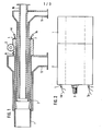
- Fig. 1 shows the known ring burner with the integrated ignition device according to the invention.
- the ring burner consists of several concentric tubes with connecting flanges, from the inside to the outside of the primary air tube 10, the coal dust tube 11 and the secondary air tube 12.
- the ignition tube 2 according to the invention is arranged between the coal dust tube 11 and the secondary air tube 12; it consists of a heat-resistant, electrically non-conductive material, for example ceramic.
- the dust igniter 1 itself is located at the head of the ignition tube 2 and is firmly connected to the latter. It consists of an electrically conductive resistance alloy, for example Konstantan, Megapyr II or the like, which is heated up to red heat by applying an electrical voltage.
- the dust igniter 1 is secured against ground by the non-conductive ignition tube 2.
- Ignition tube 2 can be retracted into the secondary air tube 12 by means of the toothed rack 6 and drive 5.
- a low voltage according to VDE 0105 ⁇ 5a-d, or a voltage via an isolating transformer and movable cables can be fed to the power connections of the threaded bolts, not shown here, as current feed.
- the temperature sensors 4 and 7 are installed with their thermal voltage taps 4a and 7a through the ignition tube 2 in the dust igniter.
- FIG. 2 shows in detail a side view of the ignition tube 2 with the dust igniter 1 in front of it.
- the threaded bolt 3 can be seen here (while the threaded bolt 8 is covered) and the thermal voltage taps 4a and 7a of the temperature sensors 4 and 7.
- Fig. 3 shows the dust igniter 1 with its connections in detail and Fig. 4 shows a section AA through the dust igniter 1.
- Threaded bolt 3 screwed on the front edge in the dust igniter 1 and the threaded bolt 8 partially hidden by it and screwed on the rear edge see.
- the threaded bolt 8 is also guided up to the screw connection through the insulating tube 9 in the dust igniter 1.
- the circuit of the dust igniter 1 can be carried out via different segments of the dust igniter 1 connected in series or in series, as a result of which different temperatures of the dust igniter 1 can be achieved.
- the threaded bolts 3 and 8 can therefore, depending on the circuit, be the same length.
- the two temperature sensors 4 and 7 are housed in bores of different lengths in order to measure the temperature over a wide range. For this purpose, the thermal voltage is removed at the thermal voltage taps 4a and 7a.
- FIG. 5 shows the ignition tube 2 in detail and FIG. 6 shows a section B-B through the ignition tube 2.
- the two large bores for the threaded bolts 3 and 8 and the two small bores for the temperature sensors 4 and 7 can be seen.
- the ignition device operates as follows: as soon as the dust igniter 1 is caused to glow by the current flowing through it to such an extent that its temperature is at or above the ignition temperature of the coal dust, it ignites to form an ignition flame in the ring burner.
- the required combustion air is supplied through the primary air pipe 10, and in the case of lack of air also through the secondary air pipe 12 of the ring burner.
- the ignition device can be switched off and returned to the ring burner. It remains in the secondary air flow during the operation of the ring burner until it is required again for a new ignition process or when the ring burner is operated at low load.
- the ignition process can also be controlled automatically.
- the advantages of the invention consist in particular in that the coal dust present for the burner can be ignited with the additional devices necessary for the ignition process without additional oil and gas burners. In addition, there is no need for additional storage and spare parts, as well as inspections that are regularly required with the known pilot burners. The subsequent installation of the ignition device according to the invention in existing coal dust burners is also possible.
Landscapes
- Engineering & Computer Science (AREA)
- Chemical & Material Sciences (AREA)
- Combustion & Propulsion (AREA)
- Mechanical Engineering (AREA)
- General Engineering & Computer Science (AREA)
- Regulation And Control Of Combustion (AREA)
- Feeding And Controlling Fuel (AREA)
Applications Claiming Priority (2)
| Application Number | Priority Date | Filing Date | Title |
|---|---|---|---|
| DE3238206 | 1982-10-15 | ||
| DE19823238206 DE3238206A1 (de) | 1982-10-15 | 1982-10-15 | Zuendeinrichtung fuer kohlenstaubfeuerungen |
Publications (1)
| Publication Number | Publication Date |
|---|---|
| EP0108923A1 true EP0108923A1 (fr) | 1984-05-23 |
Family
ID=6175766
Family Applications (1)
| Application Number | Title | Priority Date | Filing Date |
|---|---|---|---|
| EP83110051A Withdrawn EP0108923A1 (fr) | 1982-10-15 | 1983-10-08 | Dispositif d'allumage pour appareils à combustion de charbon pulvérisé |
Country Status (3)
| Country | Link |
|---|---|
| EP (1) | EP0108923A1 (fr) |
| DE (1) | DE3238206A1 (fr) |
| DK (1) | DK448483A (fr) |
Cited By (7)
| Publication number | Priority date | Publication date | Assignee | Title |
|---|---|---|---|---|
| GB2443430A (en) * | 2006-10-31 | 2008-05-07 | Petroleo Brasileiro Sa | Retractable igniter |
| WO2009087416A3 (fr) * | 2008-01-08 | 2009-10-29 | Robert Mayberry Marshall | Procédés et appareil pour l'allumage et la combustion de carburant particulaire |
| EP2009351A3 (fr) * | 2007-06-28 | 2009-11-04 | Hitachi Power Europe GmbH | Brûleur à charbon carbonisé destiné à l'allumage de combustible transporté dans un transport en phase dense |
| CN102519037A (zh) * | 2011-12-26 | 2012-06-27 | 上海锅炉厂有限公司 | 一种等离子无油点火燃烧器 |
| WO2013056524A1 (fr) * | 2011-10-18 | 2013-04-25 | 上海锅炉厂有限公司 | Système d'allumage de feu sans huile à plasma dans un environnement enrichi d'oxygène |
| US10054311B2 (en) | 2011-12-20 | 2018-08-21 | General Electric Technology Gmbh | Burner for burning a pulverulent fuel for a boiler having a plasma ignition torch |
| US11555612B2 (en) * | 2017-11-29 | 2023-01-17 | Babcock Power Services, Inc. | Dual fuel direct ignition burners |
Citations (4)
| Publication number | Priority date | Publication date | Assignee | Title |
|---|---|---|---|---|
| US2361117A (en) * | 1941-12-16 | 1944-10-24 | Fernley E Millett | Powdered fuel burner |
| DE917208C (de) * | 1939-10-24 | 1954-08-26 | Walther & Cie Ag | Einrichtung zum Zuenden von Kohlenstaubbrennern |
| DE2933040B1 (de) * | 1979-08-16 | 1980-12-11 | Steinmueller Gmbh L & C | Verfahren zum Zuenden einer Kohlenstaub-Rundbrennerflamme |
| DE3105540A1 (de) * | 1981-02-16 | 1982-09-02 | Steag Ag, 4300 Essen | Verfahren zum zuenden eines als rundbrenner ausgebildeten staub-leistungsbrenners mit zentral im leistungsbrenner angeordnetem staub-zuendbrenner mit pneumatischer haltung der zuendstaubflamme und brenneranordnung zur durchfuehrung des verfahrens |
Family Cites Families (7)
| Publication number | Priority date | Publication date | Assignee | Title |
|---|---|---|---|---|
| DE810892C (de) * | 1949-01-15 | 1951-08-13 | Karl Dipl-Ing Weiss | Elektrischer Feueranzuender fuer feste Brennstoffe |
| GB1226336A (fr) * | 1967-08-04 | 1971-03-24 | ||
| DE2400349A1 (de) * | 1974-01-04 | 1975-07-17 | Heinz Hoelter | Feuerungskessel |
| DE2806363C2 (de) * | 1977-02-18 | 1985-06-27 | Combustion Engineering, Inc., Windsor, Conn. | Verfahren zum Zünden der Verbrennung von Kohlenstaub |
| DE7707380U1 (de) * | 1977-03-10 | 1981-03-26 | Ahlgrimm, Herbert, 2000 Hamburg | Oelbrenner |
| DE2756138C3 (de) * | 1977-12-16 | 1981-09-24 | Dr. C. Otto & Comp. Gmbh, 4630 Bochum | Zündvorrichtung für Flugstromvergaser |
| DE3151476C2 (de) * | 1981-12-24 | 1986-01-02 | Kernforschungsanlage Jülich GmbH, 5170 Jülich | Schachtgenerator zur Erzeugung von Brenngas aus organischem Material |
-
1982
- 1982-10-15 DE DE19823238206 patent/DE3238206A1/de not_active Withdrawn
-
1983
- 1983-09-29 DK DK448483A patent/DK448483A/da not_active Application Discontinuation
- 1983-10-08 EP EP83110051A patent/EP0108923A1/fr not_active Withdrawn
Patent Citations (4)
| Publication number | Priority date | Publication date | Assignee | Title |
|---|---|---|---|---|
| DE917208C (de) * | 1939-10-24 | 1954-08-26 | Walther & Cie Ag | Einrichtung zum Zuenden von Kohlenstaubbrennern |
| US2361117A (en) * | 1941-12-16 | 1944-10-24 | Fernley E Millett | Powdered fuel burner |
| DE2933040B1 (de) * | 1979-08-16 | 1980-12-11 | Steinmueller Gmbh L & C | Verfahren zum Zuenden einer Kohlenstaub-Rundbrennerflamme |
| DE3105540A1 (de) * | 1981-02-16 | 1982-09-02 | Steag Ag, 4300 Essen | Verfahren zum zuenden eines als rundbrenner ausgebildeten staub-leistungsbrenners mit zentral im leistungsbrenner angeordnetem staub-zuendbrenner mit pneumatischer haltung der zuendstaubflamme und brenneranordnung zur durchfuehrung des verfahrens |
Cited By (8)
| Publication number | Priority date | Publication date | Assignee | Title |
|---|---|---|---|---|
| GB2443430A (en) * | 2006-10-31 | 2008-05-07 | Petroleo Brasileiro Sa | Retractable igniter |
| GB2443430B (en) * | 2006-10-31 | 2011-09-28 | Petryleo Brasileiro S A Petrobras | Retractable igniter |
| EP2009351A3 (fr) * | 2007-06-28 | 2009-11-04 | Hitachi Power Europe GmbH | Brûleur à charbon carbonisé destiné à l'allumage de combustible transporté dans un transport en phase dense |
| WO2009087416A3 (fr) * | 2008-01-08 | 2009-10-29 | Robert Mayberry Marshall | Procédés et appareil pour l'allumage et la combustion de carburant particulaire |
| WO2013056524A1 (fr) * | 2011-10-18 | 2013-04-25 | 上海锅炉厂有限公司 | Système d'allumage de feu sans huile à plasma dans un environnement enrichi d'oxygène |
| US10054311B2 (en) | 2011-12-20 | 2018-08-21 | General Electric Technology Gmbh | Burner for burning a pulverulent fuel for a boiler having a plasma ignition torch |
| CN102519037A (zh) * | 2011-12-26 | 2012-06-27 | 上海锅炉厂有限公司 | 一种等离子无油点火燃烧器 |
| US11555612B2 (en) * | 2017-11-29 | 2023-01-17 | Babcock Power Services, Inc. | Dual fuel direct ignition burners |
Also Published As
| Publication number | Publication date |
|---|---|
| DE3238206A1 (de) | 1984-04-19 |
| DK448483A (da) | 1984-04-16 |
| DK448483D0 (da) | 1983-09-29 |
Similar Documents
| Publication | Publication Date | Title |
|---|---|---|
| DE1918445B2 (de) | Vorrichtung zur verbrennung von fluessigen kohlenwasser stoffen | |
| DE4022111A1 (de) | Plasmabrenner fuer uebertragenen lichtbogen | |
| DE19627203C2 (de) | Brenner | |
| DE4022112C2 (de) | Plasmabrenner für übertragenen Lichtbogen | |
| EP0108923A1 (fr) | Dispositif d'allumage pour appareils à combustion de charbon pulvérisé | |
| DE3542431A1 (de) | Heizvorrichtung mit lichtbogen-plasmabrenner | |
| EP0246283A1 (fr) | Procede pour elever la temperature d'un catalyseur et dispositif pour la mise en o euvre du procede. | |
| DE1526248A1 (de) | Zuendvorrichtung | |
| DE202017000969U1 (de) | Hochspannungszündvorrichtung | |
| DE3716411C2 (fr) | ||
| DE3732491A1 (de) | Zuendbrenner fuer eine vorrichtung zum verbrennen von festkoerperpartikeln im abgas von brennkraftmaschinen | |
| DE102005008617B3 (de) | Brenner mit Flammenüberwachung und Zündeinrichtung zum Erwärmen einer Thermoprozessanlage | |
| DE3243396C2 (de) | Verdampfungsbrenner für flüssigen Brennstoff | |
| DE2223009A1 (de) | Gasbrenner | |
| DE1084977B (de) | Elektrische Zuendvorrichtung zum Zuenden des Brennstoff-Luft-Gemisches in Brennkammern von Rueckstosstriebwerken | |
| EP0352433A2 (fr) | Brûleur particulièrement pour le fonctionnement automatique | |
| DE4427953A1 (de) | Gasbrenner für Kochstellen eines Gasherdes | |
| DE1150758B (de) | Schaltungsanordnung zum Zuenden von Hochdruckgasentladungslampen hoher Leistung, insbesondere von Hochdruck-Langbogenlampen, sowie Beleuchtungsanlage mit dieser Schaltungsanordnung | |
| EP0088412B1 (fr) | Appareil automatique de chauffage au gaz | |
| DE2304215A1 (de) | Verfahren und vorrichtung zum zuenden des heizgases eines maschinenschneidbrenners | |
| DE1501972C (de) | Einrichtung zur Erzeugung elektri scher Zündfunken für ein gasgespeistes Strahlheizrohr | |
| DE1551759B2 (de) | Brennmittel-mischeinrichtung fuer einen brenner fuer einen schmelzofen | |
| CH354537A (de) | Einrichtung zum Zünden und Überwachen von Gasbrennern | |
| AT208495B (de) | Vorrichtung zum Zünden und Überwachen von Gasbrennern | |
| DE3312592C2 (de) | Zündbrenner für eine Kraftwerkskesselfeuerung |
Legal Events
| Date | Code | Title | Description |
|---|---|---|---|
| PUAI | Public reference made under article 153(3) epc to a published international application that has entered the european phase |
Free format text: ORIGINAL CODE: 0009012 |
|
| AK | Designated contracting states |
Designated state(s): AT BE CH DE FR GB LI LU NL SE |
|
| 17P | Request for examination filed |
Effective date: 19840628 |
|
| STAA | Information on the status of an ep patent application or granted ep patent |
Free format text: STATUS: THE APPLICATION IS DEEMED TO BE WITHDRAWN |
|
| 18D | Application deemed to be withdrawn |
Effective date: 19860127 |
|
| RIN1 | Information on inventor provided before grant (corrected) |
Inventor name: DEPPE, WERNER |