EP0109252A1 - Bremselement für bewegbaren Handhabungsarm - Google Patents
Bremselement für bewegbaren Handhabungsarm Download PDFInfo
- Publication number
- EP0109252A1 EP0109252A1 EP83306813A EP83306813A EP0109252A1 EP 0109252 A1 EP0109252 A1 EP 0109252A1 EP 83306813 A EP83306813 A EP 83306813A EP 83306813 A EP83306813 A EP 83306813A EP 0109252 A1 EP0109252 A1 EP 0109252A1
- Authority
- EP
- European Patent Office
- Prior art keywords
- arm
- expandable element
- braking device
- movable arm
- support
- Prior art date
- Legal status (The legal status is an assumption and is not a legal conclusion. Google has not performed a legal analysis and makes no representation as to the accuracy of the status listed.)
- Granted
Links
Images

Classifications
-
- F—MECHANICAL ENGINEERING; LIGHTING; HEATING; WEAPONS; BLASTING
- F16—ENGINEERING ELEMENTS AND UNITS; GENERAL MEASURES FOR PRODUCING AND MAINTAINING EFFECTIVE FUNCTIONING OF MACHINES OR INSTALLATIONS; THERMAL INSULATION IN GENERAL
- F16D—COUPLINGS FOR TRANSMITTING ROTATION; CLUTCHES; BRAKES
- F16D49/00—Brakes with a braking member co-operating with the periphery of a drum, wheel-rim, or the like
- F16D49/14—Brakes with a braking member co-operating with the periphery of a drum, wheel-rim, or the like shaped as a fluid-filled flexible member actuated by variation of the fluid pressure
-
- B—PERFORMING OPERATIONS; TRANSPORTING
- B25—HAND TOOLS; PORTABLE POWER-DRIVEN TOOLS; MANIPULATORS
- B25J—MANIPULATORS; CHAMBERS PROVIDED WITH MANIPULATION DEVICES
- B25J19/00—Accessories fitted to manipulators, e.g. for monitoring, for viewing; Safety devices combined with or specially adapted for use in connection with manipulators
- B25J19/0004—Braking devices
-
- B—PERFORMING OPERATIONS; TRANSPORTING
- B25—HAND TOOLS; PORTABLE POWER-DRIVEN TOOLS; MANIPULATORS
- B25J—MANIPULATORS; CHAMBERS PROVIDED WITH MANIPULATION DEVICES
- B25J9/00—Program-controlled manipulators
- B25J9/10—Program-controlled manipulators characterised by positioning means for manipulator elements
- B25J9/14—Program-controlled manipulators characterised by positioning means for manipulator elements fluid
- B25J9/146—Rotary actuators
Definitions
- This invention concerns braking devices for movable arm assembliies such as robot arm assemblies.
- the invention also concerns robots having arm assemblies including braking devices.
- It LS an object of the present invention to provide a bnaking device For use in such arms.
- an incompressible fluid such as oil
- the expandable element is located between an external cylindrical surface of a knuckle at the inboard end of the movable arm and an outer bounding sleeve forming part of or attached to the support for the movable arm.
- annular expandable element is sandwiched between the internal cylindrical face of a circular recess formed at an end face of one end of the movable arm which is located within the support therefor and the latter includes a cylindrical protrusion which fits into the recess and provides an externl cylindrical surface for the expandable element.
- the element and the supporrting or bounding surfaces are so-axial to the axes of poxot ing of the arm.
- the expandable element when expanded under fluid pressure, will cause the rotatable member to lock on or in the support and prevent rotation of the movable member relative to the support.
- bearing means is provided for the movable arm within the support additional to any bearing surface provided by the expandable element and preferably the material from which the expandable element is formed and the material of at least the surface in contact with the expandable element and which has to move relative thereto, is selected so as to be compatible with the wear which will inevitably occur with relative movement of the arm and the expandable element.
- the fluid which is supplied to the expandable element is an oil such as is used in hydraulic braking systems. and an air/oil intensifier is provided for amplifyinng airline pressure (typically 60 to 80 psi) to a higher oil pressure bu providing a large diaphragm over which the air pressure acts and a smaller diameter piston movable in a cylinder containing the oil. Air pressure acting over the larger diameter is thus converted in the ratio of the areas to a high pressure acting over the smaller area of the piston on the oil.
- airline pressure typically 60 to 80 psi
- a conventional control valve may be provided for supplying air under pressure to the air oil intensifier and for venting the pressurised space in the intensifier when the pressure is to be released.
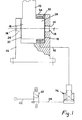
- a movable arm 10 such as the final movable element of a multiple element robotic arm assembly includes an enlarged generally cylindrical inboard end 12 having stub axles 14 and 16 extending from opposite flat end faces 18 and 20 respectively.
- the stub axles are co-axial and are locaated within and run in appropriately sized and aligned circular apertures 22 and 24 in a housing 26 forming a support for the arm 10.
- the arm 10 will be movable relative to the housing 26, so that the arm can be moved to perform a desired function.
- This movement of the arm has to be hiqhly accurate so that the tip of the arm can be positioned precisely ]in each operating cycle, and a system, such is system of meshing qears, will control relative movement between the parts.
- This movement comtrol mechanism is not shown in the Figures.
- the arm 10 extends off centre from the enlarged cylindrical end 20 so that there is an exposed cylindrical surface 28.
- an expandable element 30 in the form of an annular sleeve element to which oil can be supplied under pressure along a fluid line (shown diagrammatically only) 32.
- the line passes through the housing 26 and a ring 34 which forms an annular support element for the sleeve 30.
- the ring 34 is shown as being separate from but secured to the internal wall of the housing 26.
- the oil line 32 is supplied with oil under high pressure from an air/oil intensifier unit generally designated 36.
- the air is supplied to the latter via a line 38 from a control valve 40 supplied with air from an airline 42.
- Figure 2 shows a similar arrangement of braking device and similar items have been referenced by the same reference numerals.
- the arm 10 has an internal cylindrical face 44 within an annular recess 46 in an end face of the cylindrical end of the arm 10, and the wall of the housing 26 which faces this annular recess 46 is formed with an annular upstand 48 which fits into the recess and provides the requisite clearance between its outer surface and the cylindrical face 44.
- 'rhe expandable sleeve 30 is sandwiched between the cylindrical face 44 and the annular upstand 48.
Landscapes
- Engineering & Computer Science (AREA)
- Mechanical Engineering (AREA)
- General Engineering & Computer Science (AREA)
- Robotics (AREA)
- Physics & Mathematics (AREA)
- Fluid Mechanics (AREA)
- Manipulator (AREA)
- Braking Arrangements (AREA)
- Pivots And Pivotal Connections (AREA)
- Magnetic Heads (AREA)
- Bidet-Like Cleaning Device And Other Flush Toilet Accessories (AREA)
- Power Steering Mechanism (AREA)
- Valve Device For Special Equipments (AREA)
Priority Applications (1)
| Application Number | Priority Date | Filing Date | Title |
|---|---|---|---|
| AT83306813T ATE38953T1 (de) | 1982-11-10 | 1983-11-09 | Bremselement fuer bewegbaren handhabungsarm. |
Applications Claiming Priority (2)
| Application Number | Priority Date | Filing Date | Title |
|---|---|---|---|
| GB8232077 | 1982-11-10 | ||
| GB8232077 | 1982-11-10 |
Publications (2)
| Publication Number | Publication Date |
|---|---|
| EP0109252A1 true EP0109252A1 (de) | 1984-05-23 |
| EP0109252B1 EP0109252B1 (de) | 1988-11-30 |
Family
ID=10534159
Family Applications (1)
| Application Number | Title | Priority Date | Filing Date |
|---|---|---|---|
| EP83306813A Expired EP0109252B1 (de) | 1982-11-10 | 1983-11-09 | Bremselement für bewegbaren Handhabungsarm |
Country Status (7)
| Country | Link |
|---|---|
| US (1) | US4625836A (de) |
| EP (1) | EP0109252B1 (de) |
| JP (2) | JPS59107897A (de) |
| AT (1) | ATE38953T1 (de) |
| DE (1) | DE3378567D1 (de) |
| ES (1) | ES8500119A1 (de) |
| GB (1) | GB2129514B (de) |
Cited By (4)
| Publication number | Priority date | Publication date | Assignee | Title |
|---|---|---|---|---|
| FR2543870A1 (fr) * | 1983-04-09 | 1984-10-12 | Blohm Voss Ag | Unite formant bras d'actionnement multiaxial librement programmable, en particulier robot industriel |
| GB2171074A (en) * | 1985-02-19 | 1986-08-20 | Lamb Sceptre Ltd | Improvements in robot arms |
| WO1988009601A1 (en) * | 1987-05-22 | 1988-12-01 | Adcam Ab | Manually operated surface component assembler |
| WO1989001391A1 (en) * | 1987-08-07 | 1989-02-23 | Franck Joseph Velghe | Arm consisting of angularly displaceable linkages |
Families Citing this family (13)
| Publication number | Priority date | Publication date | Assignee | Title |
|---|---|---|---|---|
| JPS6125795A (ja) * | 1984-07-10 | 1986-02-04 | 株式会社ダイフク | ロボツトア−ムの制動装置 |
| US4751864A (en) * | 1987-03-30 | 1988-06-21 | Cincinnati Milacron Inc. | Cutting tool having an intensifier |
| DE3939349A1 (de) * | 1989-11-29 | 1991-06-06 | Krupp Gmbh | Einrichtung zur handhabung insbesondere von gegenstaenden aus nachgiebigen werkstoffen |
| EP0453826B1 (de) * | 1990-04-27 | 1995-02-08 | Rockwell International Corporation | Robotergelenk |
| US5115113A (en) * | 1990-09-24 | 1992-05-19 | General Motors Corporation | Spot welding method and apparatus having weld electrode lock-up |
| GB2273282B (en) * | 1992-12-10 | 1997-06-04 | O Brien Brian J | Powered variable geometry structural unit |
| JP2004042232A (ja) * | 2002-07-15 | 2004-02-12 | Tokai Univ | ロボットの関節制動装置 |
| US9915241B2 (en) * | 2013-03-14 | 2018-03-13 | Woodward, Inc. | Rotary vane actuator with fluid actuated mechanical lock |
| JP2016187858A (ja) * | 2015-03-30 | 2016-11-04 | 川崎重工業株式会社 | ロボットアーム固定装置およびロボット |
| EP4019796B1 (de) * | 2019-09-30 | 2024-06-12 | Siemens Ltd., China | Bremsanordnung und roboterverbindung damit, und roboter |
| WO2021062692A1 (zh) * | 2019-09-30 | 2021-04-08 | 西门子(中国)有限公司 | 固态刹车机构及包括该固态刹车机构的机器人 |
| CN110722594B (zh) * | 2019-10-27 | 2022-08-09 | 葛军 | 一种锁紧力度可调的转动关节 |
| FR3103096B1 (fr) * | 2019-11-15 | 2022-11-11 | Robocath | Bras articule de support d’instrument medical souple allonge |
Citations (4)
| Publication number | Priority date | Publication date | Assignee | Title |
|---|---|---|---|---|
| CH139566A (de) * | 1929-02-28 | 1930-04-30 | Streuli Gottfr | Einrichtung zur Verbindung eines rotierenden Organes mit einem Träger. |
| US2257610A (en) * | 1939-02-16 | 1941-09-30 | Gen Tire & Rubber Co | Motor control and brake mechanism |
| GB616799A (en) * | 1945-02-28 | 1949-01-27 | G S P Guillemin Sergot Pegard | Improvements in or relating to machine tools |
| FR2283760A1 (fr) * | 1974-09-06 | 1976-04-02 | Hagenuk Neufeldt Kuhnke Gmbh | Dispositif programmable pour execution mecanique d'operations de travail |
Family Cites Families (18)
| Publication number | Priority date | Publication date | Assignee | Title |
|---|---|---|---|---|
| FR733564A (fr) * | 1932-03-16 | 1932-10-07 | Dispositif hydraulique ou pneumatique pour le freinage des roues de véhicules automobiles, pour obtenir l'accouplement d'organes rotatifs, etc. | |
| GB405957A (en) * | 1932-05-05 | 1934-02-05 | Andrew Gordon Wilson | Improvements in or relating to variable speed gearing |
| US2174724A (en) * | 1937-03-26 | 1939-10-03 | Goodrich Co B F | Brake |
| US2930453A (en) * | 1955-08-16 | 1960-03-29 | Russell E Mcnamara | Complete surface contact brake |
| US2998869A (en) * | 1959-03-10 | 1961-09-05 | American Brake Shoe Co | Power operated brake operating apparatus |
| US3205019A (en) * | 1962-06-06 | 1965-09-07 | Continental Can Co | Hydraulically operated brake mechanism |
| GB938538A (en) * | 1962-07-24 | 1963-10-02 | Fawick Corp | Fluid-actuated clutch or brake |
| DE1535050A1 (de) * | 1964-09-01 | 1970-02-12 | Zinser Textilmaschinen Gmbh | Backenbremse fuer Spindeln von Spinn- und Zwirnmaschinen |
| FR1564013A (de) * | 1968-03-06 | 1969-04-18 | ||
| DE1926419A1 (de) * | 1969-05-23 | 1970-12-10 | Univeg Maschinen Und Appbau Gm | Putzvorrichtung fuer Streckwerke von Spinnereimaschinen |
| SE355516B (de) * | 1970-12-28 | 1973-04-30 | Kaufeldt Ingenjors Ab R | |
| JPS515016Y2 (de) * | 1971-09-29 | 1976-02-12 | ||
| JPS5525038B2 (de) * | 1974-04-04 | 1980-07-03 | ||
| JPS6058011B2 (ja) * | 1975-08-12 | 1985-12-18 | 凸版印刷株式会社 | ブロ−成形用多層パリソン成形装置 |
| SU676764A1 (ru) * | 1978-02-06 | 1979-07-30 | Рязанское специальное конструкторское бюро станкостроения | Пневмогидравлический мультипликатор |
| YU231478A (en) * | 1978-10-02 | 1982-06-30 | Radivoje Mirkovic | Cylindrical starter with a brae |
| JPS569189A (en) * | 1979-06-27 | 1981-01-30 | Hitachi Ltd | Simple robot |
| SU848349A1 (ru) * | 1979-10-11 | 1981-07-23 | Предприятие П/Я А-7438 | Промышленный робот |
-
1983
- 1983-11-07 JP JP58209761A patent/JPS59107897A/ja active Pending
- 1983-11-07 US US06/549,318 patent/US4625836A/en not_active Expired - Fee Related
- 1983-11-08 ES ES527095A patent/ES8500119A1/es not_active Expired
- 1983-11-09 DE DE8383306813T patent/DE3378567D1/de not_active Expired
- 1983-11-09 AT AT83306813T patent/ATE38953T1/de not_active IP Right Cessation
- 1983-11-09 GB GB08329902A patent/GB2129514B/en not_active Expired
- 1983-11-09 EP EP83306813A patent/EP0109252B1/de not_active Expired
-
1990
- 1990-08-24 JP JP1990089128U patent/JPH0333089U/ja active Pending
Patent Citations (4)
| Publication number | Priority date | Publication date | Assignee | Title |
|---|---|---|---|---|
| CH139566A (de) * | 1929-02-28 | 1930-04-30 | Streuli Gottfr | Einrichtung zur Verbindung eines rotierenden Organes mit einem Träger. |
| US2257610A (en) * | 1939-02-16 | 1941-09-30 | Gen Tire & Rubber Co | Motor control and brake mechanism |
| GB616799A (en) * | 1945-02-28 | 1949-01-27 | G S P Guillemin Sergot Pegard | Improvements in or relating to machine tools |
| FR2283760A1 (fr) * | 1974-09-06 | 1976-04-02 | Hagenuk Neufeldt Kuhnke Gmbh | Dispositif programmable pour execution mecanique d'operations de travail |
Cited By (5)
| Publication number | Priority date | Publication date | Assignee | Title |
|---|---|---|---|---|
| FR2543870A1 (fr) * | 1983-04-09 | 1984-10-12 | Blohm Voss Ag | Unite formant bras d'actionnement multiaxial librement programmable, en particulier robot industriel |
| US4693665A (en) * | 1983-04-09 | 1987-09-15 | Blohm & Voss Ag | Large force multi-axis manipulating arm unit, especially for use as an industrial robot |
| GB2171074A (en) * | 1985-02-19 | 1986-08-20 | Lamb Sceptre Ltd | Improvements in robot arms |
| WO1988009601A1 (en) * | 1987-05-22 | 1988-12-01 | Adcam Ab | Manually operated surface component assembler |
| WO1989001391A1 (en) * | 1987-08-07 | 1989-02-23 | Franck Joseph Velghe | Arm consisting of angularly displaceable linkages |
Also Published As
| Publication number | Publication date |
|---|---|
| ES527095A0 (es) | 1984-11-01 |
| JPH0333089U (de) | 1991-04-02 |
| GB2129514A (en) | 1984-05-16 |
| EP0109252B1 (de) | 1988-11-30 |
| GB8329902D0 (en) | 1983-12-14 |
| ES8500119A1 (es) | 1984-11-01 |
| JPS59107897A (ja) | 1984-06-22 |
| GB2129514B (en) | 1986-03-26 |
| ATE38953T1 (de) | 1988-12-15 |
| US4625836A (en) | 1986-12-02 |
| DE3378567D1 (en) | 1989-01-05 |
Similar Documents
| Publication | Publication Date | Title |
|---|---|---|
| EP0109252A1 (de) | Bremselement für bewegbaren Handhabungsarm | |
| US3926094A (en) | Air operated spring brake | |
| US4693665A (en) | Large force multi-axis manipulating arm unit, especially for use as an industrial robot | |
| US4362324A (en) | Jointed high pressure conduit | |
| US2395223A (en) | Vehicle brake mechanism | |
| EP0128936A1 (de) | Roboterarm und handgelenkeinheit | |
| JPH05503970A (ja) | 自己荷重型たわみ制御ロール | |
| US6311987B1 (en) | Hydraulic pressurizing arrangements | |
| EP0295514B1 (de) | Vorrichtung zur Werkstückhalterung | |
| JPH11300545A (ja) | フローティング支持装置 | |
| US4529068A (en) | Integral disk brake actuator and adjuster | |
| GB1532141A (en) | Precision heavy duty rotary indexing means | |
| US4696351A (en) | Assembly robot with reaction absorbing platform | |
| EP0559256B1 (de) | Servovorrichtung für ein Fahrzeuggetriebe | |
| US4318572A (en) | Tension-compression swivel joint with hydraulic force reaction | |
| GB2087040A (en) | Pressure treatment roll | |
| FR3134599B1 (fr) | Module pour une turbomachine d’aeronef | |
| US3804212A (en) | Vehicle wheel brake unit | |
| JPH022492B2 (de) | ||
| US5625940A (en) | Robot compliance device | |
| GB2121899A (en) | Fast fill piston for master cylinder | |
| JPS6235123A (ja) | デイスクブレ−キ | |
| EP0648942B1 (de) | Lineares pneumatisches Stellorgan mit einer umorientierbaren Verriegelungseinrichtung | |
| JPH04501243A (ja) | 流体圧自動車ブレーキシステム用駆動ユニット | |
| JPH06147378A (ja) | ロータリジョイントのシール構造 |
Legal Events
| Date | Code | Title | Description |
|---|---|---|---|
| PUAI | Public reference made under article 153(3) epc to a published international application that has entered the european phase |
Free format text: ORIGINAL CODE: 0009012 |
|
| AK | Designated contracting states |
Designated state(s): AT BE CH DE FR GB IT LI LU NL SE |
|
| 17P | Request for examination filed |
Effective date: 19841019 |
|
| RAP1 | Party data changed (applicant data changed or rights of an application transferred) |
Owner name: ROBOTIC SYSTEMS LIMITED |
|
| RIN1 | Information on inventor provided before grant (corrected) |
Inventor name: PIGOTT, NORMAN BRIAN |
|
| RAP1 | Party data changed (applicant data changed or rights of an application transferred) |
Owner name: LITTON U.K. LIMITED |
|
| ITF | It: translation for a ep patent filed | ||
| GRAA | (expected) grant |
Free format text: ORIGINAL CODE: 0009210 |
|
| AK | Designated contracting states |
Kind code of ref document: B1 Designated state(s): AT BE CH DE FR IT LI LU NL SE |
|
| REF | Corresponds to: |
Ref document number: 38953 Country of ref document: AT Date of ref document: 19881215 Kind code of ref document: T |
|
| REF | Corresponds to: |
Ref document number: 3378567 Country of ref document: DE Date of ref document: 19890105 |
|
| ET | Fr: translation filed | ||
| PGFP | Annual fee paid to national office [announced via postgrant information from national office to epo] |
Ref country code: LU Payment date: 19890913 Year of fee payment: 7 |
|
| PGFP | Annual fee paid to national office [announced via postgrant information from national office to epo] |
Ref country code: FR Payment date: 19890926 Year of fee payment: 7 |
|
| PLBE | No opposition filed within time limit |
Free format text: ORIGINAL CODE: 0009261 |
|
| STAA | Information on the status of an ep patent application or granted ep patent |
Free format text: STATUS: NO OPPOSITION FILED WITHIN TIME LIMIT |
|
| PGFP | Annual fee paid to national office [announced via postgrant information from national office to epo] |
Ref country code: DE Payment date: 19891014 Year of fee payment: 7 |
|
| PGFP | Annual fee paid to national office [announced via postgrant information from national office to epo] |
Ref country code: AT Payment date: 19891114 Year of fee payment: 7 |
|
| 26N | No opposition filed | ||
| PGFP | Annual fee paid to national office [announced via postgrant information from national office to epo] |
Ref country code: SE Payment date: 19891121 Year of fee payment: 7 |
|
| ITTA | It: last paid annual fee | ||
| PG25 | Lapsed in a contracting state [announced via postgrant information from national office to epo] |
Ref country code: LU Free format text: LAPSE BECAUSE OF NON-PAYMENT OF DUE FEES Effective date: 19891130 Ref country code: LI Effective date: 19891130 Ref country code: CH Effective date: 19891130 Ref country code: BE Effective date: 19891130 |
|
| PGFP | Annual fee paid to national office [announced via postgrant information from national office to epo] |
Ref country code: NL Payment date: 19891130 Year of fee payment: 7 |
|
| REG | Reference to a national code |
Ref country code: FR Ref legal event code: CA |
|
| BERE | Be: lapsed |
Owner name: LITTON U.K. LTD Effective date: 19891130 |
|
| REG | Reference to a national code |
Ref country code: CH Ref legal event code: PL |
|
| PG25 | Lapsed in a contracting state [announced via postgrant information from national office to epo] |
Ref country code: AT Effective date: 19901109 |
|
| PG25 | Lapsed in a contracting state [announced via postgrant information from national office to epo] |
Ref country code: SE Effective date: 19901110 |
|
| PG25 | Lapsed in a contracting state [announced via postgrant information from national office to epo] |
Ref country code: NL Effective date: 19910601 |
|
| NLV4 | Nl: lapsed or anulled due to non-payment of the annual fee | ||
| PG25 | Lapsed in a contracting state [announced via postgrant information from national office to epo] |
Ref country code: FR Effective date: 19910731 |
|
| PG25 | Lapsed in a contracting state [announced via postgrant information from national office to epo] |
Ref country code: DE Effective date: 19910801 |
|
| REG | Reference to a national code |
Ref country code: FR Ref legal event code: ST |
|
| EUG | Se: european patent has lapsed |
Ref document number: 83306813.3 Effective date: 19910705 |