EP0109735A2 - Selbsttätige Verdrahtungsanordnung mit drehbarer Einsetzwerkzeugsausrüstung - Google Patents
Selbsttätige Verdrahtungsanordnung mit drehbarer Einsetzwerkzeugsausrüstung Download PDFInfo
- Publication number
- EP0109735A2 EP0109735A2 EP83305486A EP83305486A EP0109735A2 EP 0109735 A2 EP0109735 A2 EP 0109735A2 EP 83305486 A EP83305486 A EP 83305486A EP 83305486 A EP83305486 A EP 83305486A EP 0109735 A2 EP0109735 A2 EP 0109735A2
- Authority
- EP
- European Patent Office
- Prior art keywords
- wire
- inserters
- substrate
- adjacent
- wires
- Prior art date
- Legal status (The legal status is an assumption and is not a legal conclusion. Google has not performed a legal analysis and makes no representation as to the accuracy of the status listed.)
- Withdrawn
Links
Images







Classifications
-
- H—ELECTRICITY
- H01—ELECTRIC ELEMENTS
- H01R—ELECTRICALLY-CONDUCTIVE CONNECTIONS; STRUCTURAL ASSOCIATIONS OF A PLURALITY OF MUTUALLY-INSULATED ELECTRICAL CONNECTING ELEMENTS; COUPLING DEVICES; CURRENT COLLECTORS
- H01R43/00—Apparatus or processes specially adapted for manufacturing, assembling, maintaining, or repairing of line connectors or current collectors or for joining electric conductors
- H01R43/01—Apparatus or processes specially adapted for manufacturing, assembling, maintaining, or repairing of line connectors or current collectors or for joining electric conductors for connecting unstripped conductors to contact members having insulation cutting edges
-
- H—ELECTRICITY
- H05—ELECTRIC TECHNIQUES NOT OTHERWISE PROVIDED FOR
- H05K—PRINTED CIRCUITS; CASINGS OR CONSTRUCTIONAL DETAILS OF ELECTRIC APPARATUS; MANUFACTURE OF ASSEMBLAGES OF ELECTRICAL COMPONENTS
- H05K13/00—Apparatus or processes specially adapted for manufacturing or adjusting assemblages of electric components
- H05K13/06—Wiring by machine
-
- Y—GENERAL TAGGING OF NEW TECHNOLOGICAL DEVELOPMENTS; GENERAL TAGGING OF CROSS-SECTIONAL TECHNOLOGIES SPANNING OVER SEVERAL SECTIONS OF THE IPC; TECHNICAL SUBJECTS COVERED BY FORMER USPC CROSS-REFERENCE ART COLLECTIONS [XRACs] AND DIGESTS
- Y10—TECHNICAL SUBJECTS COVERED BY FORMER USPC
- Y10T—TECHNICAL SUBJECTS COVERED BY FORMER US CLASSIFICATION
- Y10T29/00—Metal working
- Y10T29/49—Method of mechanical manufacture
- Y10T29/49002—Electrical device making
- Y10T29/49117—Conductor or circuit manufacturing
- Y10T29/49124—On flat or curved insulated base, e.g., printed circuit, etc.
- Y10T29/49155—Manufacturing circuit on or in base
- Y10T29/49162—Manufacturing circuit on or in base by using wire as conductive path
-
- Y—GENERAL TAGGING OF NEW TECHNOLOGICAL DEVELOPMENTS; GENERAL TAGGING OF CROSS-SECTIONAL TECHNOLOGIES SPANNING OVER SEVERAL SECTIONS OF THE IPC; TECHNICAL SUBJECTS COVERED BY FORMER USPC CROSS-REFERENCE ART COLLECTIONS [XRACs] AND DIGESTS
- Y10—TECHNICAL SUBJECTS COVERED BY FORMER USPC
- Y10T—TECHNICAL SUBJECTS COVERED BY FORMER US CLASSIFICATION
- Y10T29/00—Metal working
- Y10T29/51—Plural diverse manufacturing apparatus including means for metal shaping or assembling
- Y10T29/5136—Separate tool stations for selective or successive operation on work
- Y10T29/5137—Separate tool stations for selective or successive operation on work including assembling or disassembling station
- Y10T29/5138—Separate tool stations for selective or successive operation on work including assembling or disassembling station and means to machine work part to fit cooperating work part
-
- Y—GENERAL TAGGING OF NEW TECHNOLOGICAL DEVELOPMENTS; GENERAL TAGGING OF CROSS-SECTIONAL TECHNOLOGIES SPANNING OVER SEVERAL SECTIONS OF THE IPC; TECHNICAL SUBJECTS COVERED BY FORMER USPC CROSS-REFERENCE ART COLLECTIONS [XRACs] AND DIGESTS
- Y10—TECHNICAL SUBJECTS COVERED BY FORMER USPC
- Y10T—TECHNICAL SUBJECTS COVERED BY FORMER US CLASSIFICATION
- Y10T29/00—Metal working
- Y10T29/51—Plural diverse manufacturing apparatus including means for metal shaping or assembling
- Y10T29/5147—Plural diverse manufacturing apparatus including means for metal shaping or assembling including composite tool
- Y10T29/5148—Plural diverse manufacturing apparatus including means for metal shaping or assembling including composite tool including severing means
- Y10T29/515—Plural diverse manufacturing apparatus including means for metal shaping or assembling including composite tool including severing means to trim electric component
Definitions
- Either one or two wires may be fed depending on whether one or both idlers are pivoted to engage the wires against the feed wheel.
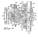
- the depth of wire insertion in the terminals may be varied by changing the pivot point of the yoke by rotating the eccentric shaft about which the yoke pivots. This permits two levels of wire to be inserted in a single terminal.
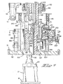
- the angular orientation of eccentric shaft 114 is determined by air cylinder 116 acting on a lever at the opposite end of shaft 114 from shaft support 115, which also serves for mounting switch bracket 120. See also Figure 6.
- Switches 119 on switch bracket 120 are actuated by switch vane 118 to provide feedback as to position of shaft 114, which determines the limits of travel of the rotation housing 150.
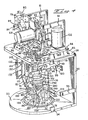
- the housing 150 acts on ram 180 which drives wire inserters to insert wires into terminals, the angular position of eccentric shaft 114 thus determining insertion depth.
- the bracket 112 also has a follower 130 journaled thereto which acts on stops 132 and 133 to dampen movement of the yokes 113, as will be shown in greater-detail in Figures 6 and 6A.
- Spring 144 serves to prevent downward motion when air pressure is shut off.
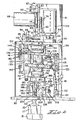
- Bracket 141 on the underside of plate 58 carries switches 140 which provide feedback to the controller as to the position of bracket 112.
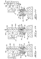
- Figures 11A through 11 D show the termination of the end of a wire
- termination of a mid portion is possible since the forward wire guide 171 is profiled with a trough on the vertical edge which faces shear block 45, which would permit the wire to pass therethrough so that a continuous length of wire could be terminated to terminals in several connectors.
- an additional through-wire type inserter 170 is located adjacent to and behind that shown here, thus permitting simultaneous termination of two wires, which the apparatus is arranged to feed in parallel relationship. The upper portion of inserters 170 is shown cut away so that inserters 175 are visible.
- the wires are fed and the X-Y table moves so that the wire passes through a by-pass lead-in 39 ( Figure 3) between terminals in the adjacent card edge connector 30.
- the X-Y table jogs a distance equal to one half the spacing between terminals so that the wire will be aligned with a slot 36 in a terminal in the adjacent row.
- the other idler wheel 72 is engaged and the second wire is again fed so that both wires are terminated by inserter 170, as shown at POSITION 4.
- Figure 15A is a plan view of the rotation sensor 240 mounted on tubular section 162 of center shaft 160 (see also Figure 6).
- Switch vanes 241 located in four orthogonal orientations on two levels about the periphery of the sensor 240 provide feedback to the controller as to the angular position of the insertion tooling via switches 242.
- Figure 15B a side view showing the position of the sensor between upper plate 58 and the rotation housing 150.
Landscapes
- Engineering & Computer Science (AREA)
- Manufacturing & Machinery (AREA)
- Microelectronics & Electronic Packaging (AREA)
- Supply And Installment Of Electrical Components (AREA)
- Manufacturing Of Electrical Connectors (AREA)
Applications Claiming Priority (2)
| Application Number | Priority Date | Filing Date | Title |
|---|---|---|---|
| US426455 | 1982-09-29 | ||
| US06/426,455 US4499648A (en) | 1982-09-29 | 1982-09-29 | Automatic wiring apparatus with rotatable insertion tooling |
Publications (2)
| Publication Number | Publication Date |
|---|---|
| EP0109735A2 true EP0109735A2 (de) | 1984-05-30 |
| EP0109735A3 EP0109735A3 (de) | 1985-12-04 |
Family
ID=23690876
Family Applications (1)
| Application Number | Title | Priority Date | Filing Date |
|---|---|---|---|
| EP83305486A Withdrawn EP0109735A3 (de) | 1982-09-29 | 1983-09-19 | Selbsttätige Verdrahtungsanordnung mit drehbarer Einsetzwerkzeugsausrüstung |
Country Status (3)
| Country | Link |
|---|---|
| US (1) | US4499648A (de) |
| EP (1) | EP0109735A3 (de) |
| JP (1) | JPS5994500A (de) |
Cited By (4)
| Publication number | Priority date | Publication date | Assignee | Title |
|---|---|---|---|---|
| EP0193490A1 (de) * | 1985-02-22 | 1986-09-03 | Siemens Aktiengesellschaft | Verfahren zur Verlegung von elektrischen Leitern in einem Verdrahtungsfeld |
| EP0429943A1 (de) * | 1989-12-01 | 1991-06-05 | STOCKO Metallwarenfabriken Henkels und Sohn GmbH & Co | Vorrichtung für die Restbestückung von vorbestückten Kabelbäumen |
| EP0626739A3 (de) * | 1993-04-20 | 1996-04-24 | Vossloh Schwabe Gmbh | Leitungsverlegewerkzeug. |
| CN116833324A (zh) * | 2023-06-20 | 2023-10-03 | 汤始建华建材(上海)有限公司 | 一种用于管桩端板和套箍旋铆的自动组装系统及方法 |
Families Citing this family (6)
| Publication number | Priority date | Publication date | Assignee | Title |
|---|---|---|---|---|
| US4642873A (en) * | 1983-10-31 | 1987-02-17 | At&T Technologies, Inc. | Apparatus for cutting and stuffing wires into connector contacts |
| DE3523308A1 (de) * | 1984-06-27 | 1986-01-09 | Nippon Gakki Seizo K.K., Hamamatsu, Shizuoka | Verfahren und vorrichtung zur herstellung von kabelbaeumen unter verwendung von schneid-/klemmverbindern |
| JPH10106370A (ja) * | 1996-09-27 | 1998-04-24 | Harness Sogo Gijutsu Kenkyusho:Kk | ワイヤーハーネスの製造 |
| US6641025B2 (en) * | 2001-08-30 | 2003-11-04 | Micron Technology, Inc. | Threading tool and method for bond wire capillary tubes |
| CN114545140B (zh) * | 2022-04-25 | 2022-07-05 | 合肥航太电物理技术有限公司 | 大电流电磁脉冲注入试验装置 |
| CN117395887B (zh) * | 2023-08-11 | 2024-09-13 | 深圳市日精机电有限公司 | 自动插线机设备 |
Family Cites Families (13)
| Publication number | Priority date | Publication date | Assignee | Title |
|---|---|---|---|---|
| US3372475A (en) * | 1963-07-09 | 1968-03-12 | Amp Inc | Method for wiring |
| BE650219A (de) * | 1963-07-09 | |||
| BE663052A (de) * | 1964-04-27 | |||
| US3435858A (en) * | 1965-08-03 | 1969-04-01 | Int Standard Electric Corp | Wire wrapping machine |
| US3840962A (en) * | 1972-05-24 | 1974-10-15 | Amp Inc | Mechanical analogue computer in a wiring machine |
| US3960309A (en) * | 1974-07-31 | 1976-06-01 | International Business Machines Corporation | Fine wire twisted pair routing and connecting system |
| US4031612A (en) * | 1976-03-02 | 1977-06-28 | Commissariat A L'energie Atomique | Method and a device for the interconnection of electronic components |
| US4066317A (en) * | 1976-09-30 | 1978-01-03 | Western Electric Company, Inc. | Electrical conductor terminating system |
| JPS53116478A (en) * | 1977-03-22 | 1978-10-11 | Matsushita Electric Industrial Co Ltd | Device for inserting electric part |
| FR2466936A1 (fr) * | 1979-09-28 | 1981-04-10 | Cii Honeywell Bull | Appareil de cablage a la surface d'un substrat d'interconnexion |
| JPS5698900A (en) * | 1980-01-07 | 1981-08-08 | Hitachi Ltd | Device for automatically wiring printed circuit board |
| US4331182A (en) * | 1980-05-02 | 1982-05-25 | Burroughs Corporation | Dressing finger assembly for automatic wiring machines |
| US4387509A (en) * | 1981-08-17 | 1983-06-14 | Amp Incorporated | Method of manufacturing an electrical interconnection assembly |
-
1982
- 1982-09-29 US US06/426,455 patent/US4499648A/en not_active Expired - Fee Related
-
1983
- 1983-09-19 EP EP83305486A patent/EP0109735A3/de not_active Withdrawn
- 1983-09-22 JP JP58176117A patent/JPS5994500A/ja active Pending
Cited By (4)
| Publication number | Priority date | Publication date | Assignee | Title |
|---|---|---|---|---|
| EP0193490A1 (de) * | 1985-02-22 | 1986-09-03 | Siemens Aktiengesellschaft | Verfahren zur Verlegung von elektrischen Leitern in einem Verdrahtungsfeld |
| EP0429943A1 (de) * | 1989-12-01 | 1991-06-05 | STOCKO Metallwarenfabriken Henkels und Sohn GmbH & Co | Vorrichtung für die Restbestückung von vorbestückten Kabelbäumen |
| EP0626739A3 (de) * | 1993-04-20 | 1996-04-24 | Vossloh Schwabe Gmbh | Leitungsverlegewerkzeug. |
| CN116833324A (zh) * | 2023-06-20 | 2023-10-03 | 汤始建华建材(上海)有限公司 | 一种用于管桩端板和套箍旋铆的自动组装系统及方法 |
Also Published As
| Publication number | Publication date |
|---|---|
| US4499648A (en) | 1985-02-19 |
| EP0109735A3 (de) | 1985-12-04 |
| JPS5994500A (ja) | 1984-05-31 |
Similar Documents
| Publication | Publication Date | Title |
|---|---|---|
| US3932931A (en) | Post terminal insertion method and apparatus | |
| US4499648A (en) | Automatic wiring apparatus with rotatable insertion tooling | |
| EP2174390B1 (de) | Drahtpositionierungsvorrichtung für eine drahtanschlussmaschine | |
| US4043034A (en) | Method and apparatus for connecting conductors to terminals in connectors | |
| US4404743A (en) | Electrical harness fabrication using improved wire measuring method | |
| US4380117A (en) | Electrical harness fabricating apparatus | |
| US3837063A (en) | Post terminal insertion apparatus | |
| EP0101488B1 (de) | Verfahren und anordnung für das anbringen von zweiteiligen verbinderblöcken an einem vielleiterkabel | |
| US4125137A (en) | Apparatus for locating wires in predetermined co-planar relationship to each other | |
| JPH0232724B2 (de) | ||
| US4612700A (en) | Component insertion apparatus | |
| US4373261A (en) | Method and apparatus for manufacturing electrical harnesses | |
| EP0099623B1 (de) | Vorrichtung zur Herstellung von Endstücken an optischen Wellenleitern und Verfahren hierzu | |
| US4395818A (en) | Block loader | |
| JP2839275B2 (ja) | 選択的ワイヤ供給装置 | |
| EP0041332A2 (de) | Verfahren und Vorrichtung zum Einsetzen von elektrischen Endkontakten in Gehäuse von elektrischen Steckverbindern | |
| EP0001891A1 (de) | Vorrichtung zum Einführen von Drähten in elektrische Anschlussklemmen | |
| US4628594A (en) | Electronic circuit element insertion apparatus | |
| EP0145216B1 (de) | Maschine und Verfahren zur Kabelbaumherstellung und Drahtsortierkamm dafür | |
| WO1987001245A1 (en) | Cable harness assembly apparatus | |
| US4044451A (en) | Apparatus for inserting wires into terminals in modular type connector | |
| US6486677B2 (en) | Conductivity testing method for a sub-harness and a sub-harness manufacturing apparatus | |
| KR0164428B1 (ko) | 리본 케이블에의 커넥터 설치기 | |
| JPH07192552A (ja) | ワイヤハーネス製造装置 | |
| EP0090050A1 (de) | Vorrichtung zum einstecken elektrischer komponenten |
Legal Events
| Date | Code | Title | Description |
|---|---|---|---|
| PUAI | Public reference made under article 153(3) epc to a published international application that has entered the european phase |
Free format text: ORIGINAL CODE: 0009012 |
|
| AK | Designated contracting states |
Designated state(s): BE DE FR GB IT NL |
|
| PUAL | Search report despatched |
Free format text: ORIGINAL CODE: 0009013 |
|
| AK | Designated contracting states |
Designated state(s): BE DE FR GB IT NL |
|
| STAA | Information on the status of an ep patent application or granted ep patent |
Free format text: STATUS: THE APPLICATION HAS BEEN WITHDRAWN |
|
| 18W | Application withdrawn |
Withdrawal date: 19860120 |
|
| RIN1 | Information on inventor provided before grant (corrected) |
Inventor name: BROWN, CHRISTOPHER KINGSLEY Inventor name: OVER, WILLIAM RODERICK Inventor name: KENSINGER, LEX DONALD Inventor name: WION, DONALD ANDREW |