EP0110140B1 - Verfahren und Vorrichtung zur Herstellung eines optischen Verbindungsstückes - Google Patents
Verfahren und Vorrichtung zur Herstellung eines optischen Verbindungsstückes Download PDFInfo
- Publication number
- EP0110140B1 EP0110140B1 EP83110732A EP83110732A EP0110140B1 EP 0110140 B1 EP0110140 B1 EP 0110140B1 EP 83110732 A EP83110732 A EP 83110732A EP 83110732 A EP83110732 A EP 83110732A EP 0110140 B1 EP0110140 B1 EP 0110140B1
- Authority
- EP
- European Patent Office
- Prior art keywords
- mold
- axis
- mold part
- receiver
- parts
- Prior art date
- Legal status (The legal status is an assumption and is not a legal conclusion. Google has not performed a legal analysis and makes no representation as to the accuracy of the status listed.)
- Expired
Links
- 230000003287 optical effect Effects 0.000 title claims abstract description 9
- 238000000034 method Methods 0.000 title claims description 11
- 239000000835 fiber Substances 0.000 claims abstract description 35
- 238000000465 moulding Methods 0.000 claims abstract description 29
- 230000015572 biosynthetic process Effects 0.000 claims abstract description 8
- XBWAZCLHZCFCGK-UHFFFAOYSA-N 7-chloro-1-methyl-5-phenyl-3,4-dihydro-2h-1,4-benzodiazepin-1-ium;chloride Chemical compound [Cl-].C12=CC(Cl)=CC=C2[NH+](C)CCN=C1C1=CC=CC=C1 XBWAZCLHZCFCGK-UHFFFAOYSA-N 0.000 claims description 19
- 239000013307 optical fiber Substances 0.000 claims description 19
- 239000004033 plastic Substances 0.000 claims description 16
- 238000001746 injection moulding Methods 0.000 claims description 9
- 230000000712 assembly Effects 0.000 claims description 7
- 238000000429 assembly Methods 0.000 claims description 7
- 230000000295 complement effect Effects 0.000 claims description 4
- 238000005755 formation reaction Methods 0.000 abstract description 6
- 239000000463 material Substances 0.000 description 5
- 230000000717 retained effect Effects 0.000 description 5
- 238000012546 transfer Methods 0.000 description 4
- 230000000694 effects Effects 0.000 description 3
- 238000003754 machining Methods 0.000 description 3
- 230000005540 biological transmission Effects 0.000 description 2
- 230000008878 coupling Effects 0.000 description 2
- 238000010168 coupling process Methods 0.000 description 2
- 238000005859 coupling reaction Methods 0.000 description 2
- 238000002347 injection Methods 0.000 description 2
- 239000007924 injection Substances 0.000 description 2
- 230000014759 maintenance of location Effects 0.000 description 2
- 230000013011 mating Effects 0.000 description 2
- 230000002093 peripheral effect Effects 0.000 description 2
- 230000008901 benefit Effects 0.000 description 1
- 238000006243 chemical reaction Methods 0.000 description 1
- 238000005253 cladding Methods 0.000 description 1
- 238000004891 communication Methods 0.000 description 1
- 239000002131 composite material Substances 0.000 description 1
- 238000013461 design Methods 0.000 description 1
- 239000007788 liquid Substances 0.000 description 1
- 239000013521 mastic Substances 0.000 description 1
- 239000002184 metal Substances 0.000 description 1
- 238000012986 modification Methods 0.000 description 1
- 230000004048 modification Effects 0.000 description 1
- 239000002991 molded plastic Substances 0.000 description 1
- 238000012544 monitoring process Methods 0.000 description 1
- 230000008520 organization Effects 0.000 description 1
- 230000002441 reversible effect Effects 0.000 description 1
- 238000010079 rubber tapping Methods 0.000 description 1
- 238000007493 shaping process Methods 0.000 description 1
- 238000005476 soldering Methods 0.000 description 1
- 239000000725 suspension Substances 0.000 description 1
Images

Classifications
-
- G—PHYSICS
- G02—OPTICS
- G02B—OPTICAL ELEMENTS, SYSTEMS OR APPARATUS
- G02B6/00—Light guides; Structural details of arrangements comprising light guides and other optical elements, e.g. couplings
- G02B6/24—Coupling light guides
- G02B6/36—Mechanical coupling means
- G02B6/38—Mechanical coupling means having fibre to fibre mating means
- G02B6/3807—Dismountable connectors, i.e. comprising plugs
- G02B6/3833—Details of mounting fibres in ferrules; Assembly methods; Manufacture
- G02B6/3865—Details of mounting fibres in ferrules; Assembly methods; Manufacture fabricated by using moulding techniques
-
- B—PERFORMING OPERATIONS; TRANSPORTING
- B29—WORKING OF PLASTICS; WORKING OF SUBSTANCES IN A PLASTIC STATE IN GENERAL
- B29C—SHAPING OR JOINING OF PLASTICS; SHAPING OF MATERIAL IN A PLASTIC STATE, NOT OTHERWISE PROVIDED FOR; AFTER-TREATMENT OF THE SHAPED PRODUCTS, e.g. REPAIRING
- B29C45/00—Injection moulding, i.e. forcing the required volume of moulding material through a nozzle into a closed mould; Apparatus therefor
- B29C45/17—Component parts, details or accessories; Auxiliary operations
- B29C45/26—Moulds
-
- B—PERFORMING OPERATIONS; TRANSPORTING
- B29—WORKING OF PLASTICS; WORKING OF SUBSTANCES IN A PLASTIC STATE IN GENERAL
- B29C—SHAPING OR JOINING OF PLASTICS; SHAPING OF MATERIAL IN A PLASTIC STATE, NOT OTHERWISE PROVIDED FOR; AFTER-TREATMENT OF THE SHAPED PRODUCTS, e.g. REPAIRING
- B29C45/00—Injection moulding, i.e. forcing the required volume of moulding material through a nozzle into a closed mould; Apparatus therefor
- B29C45/17—Component parts, details or accessories; Auxiliary operations
- B29C45/40—Removing or ejecting moulded articles
-
- B—PERFORMING OPERATIONS; TRANSPORTING
- B29—WORKING OF PLASTICS; WORKING OF SUBSTANCES IN A PLASTIC STATE IN GENERAL
- B29D—PRODUCING PARTICULAR ARTICLES FROM PLASTICS OR FROM SUBSTANCES IN A PLASTIC STATE
- B29D11/00—Producing optical elements, e.g. lenses or prisms
- B29D11/0074—Production of other optical elements not provided for in B29D11/00009- B29D11/0073
- B29D11/0075—Connectors for light guides
-
- G—PHYSICS
- G02—OPTICS
- G02B—OPTICAL ELEMENTS, SYSTEMS OR APPARATUS
- G02B6/00—Light guides; Structural details of arrangements comprising light guides and other optical elements, e.g. couplings
- G02B6/24—Coupling light guides
- G02B6/26—Optical coupling means
- G02B6/32—Optical coupling means having lens focusing means positioned between opposed fibre ends
- G02B6/322—Optical coupling means having lens focusing means positioned between opposed fibre ends and having centering means being part of the lens for the self-positioning of the lightguide at the focal point, e.g. holes, wells, indents, nibs
-
- Y—GENERAL TAGGING OF NEW TECHNOLOGICAL DEVELOPMENTS; GENERAL TAGGING OF CROSS-SECTIONAL TECHNOLOGIES SPANNING OVER SEVERAL SECTIONS OF THE IPC; TECHNICAL SUBJECTS COVERED BY FORMER USPC CROSS-REFERENCE ART COLLECTIONS [XRACs] AND DIGESTS
- Y10—TECHNICAL SUBJECTS COVERED BY FORMER USPC
- Y10S—TECHNICAL SUBJECTS COVERED BY FORMER USPC CROSS-REFERENCE ART COLLECTIONS [XRACs] AND DIGESTS
- Y10S425/00—Plastic article or earthenware shaping or treating: apparatus
- Y10S425/808—Lens mold
Definitions
- This invention relates to plastic injection molding and, more particularly, to precision molding methods and apparatus for forming miniature optical components for use in optical fiber connectors, for example.
- Fiber optics connectors heretofore disclosed have generally involved precision molding or otherwise forming an enlarged plastic or metal terminal component at or near the end of each of two fibers to be connected, taking great care to achieve seating surfaces on the terminal components which are concentric with the fiber axis. Two such terminals may then be joined mechanically to retain the connected fibers in precise alignment with each other. While such connectors may be considered reteasabte or reconnectable in the manner of an electrical coupling, the need for a liquid or plastic having the same refractive index as the fibers to effect continuity of light transmission through the connection has tended to a class of connectors more truly characterized as a quasi-permanent splice than a releasable connector. Exemplary disclosures of such connectors are found in U.S. Patents No. 3,999,841; No. 4,087,158; No. 4,107,242; and No. 4,173,389.
- the preformed terminal is not only easily applied concentrically to the end of each fiber, but the transfer by way of an enlarged beam contributes to higher light- transmitting efficiencies due to the greater range of dimensional tolerances permitted in the mechanical components for releasably retaining the two terminals in operative relationship. Additionally, the conversion of the fiber optic transmitted light signals to an enlarged beam at the juncture of the two fibers permits use of beamsplitters and the like for monitoring or otherwise tapping the information represented by the transmitted light.
- the invention relates to a precision injection molding apparatus for forming a plastic component of the type having a body with a longitudinal axis, an end face, and a precision surface concentric with said axis and recessed behind said end face, said assembly comprising at least: a first, mold part having a frustoconical reference surface defining a first mold cavity portion on said axis; and a second mold part having molding surfaces to define the end face and the precision surface of the component, said second mold part and said first mold part being movable relative to each other between opened and closed positions, said second mold part having a locating surface at one end complementing said frustoconical reference surface to establish precise radial and axial orientation of said mold parts in said closed position.
- the invention relates to a method of forming at least a portion of a cavity for injection molding a precision plastic miniature optical piecepart such as a fiber optics connector terminal part having a longitudinal axis and a lens surface and an optical fiber end locating socket formation concentric with said axis.
- a precision plastic miniature optical piecepart such as a fiber optics connector terminal part having a longitudinal axis and a lens surface and an optical fiber end locating socket formation concentric with said axis.
- the invention is particularly, though not exclusively, suited for injection molding of fiber optics connector terminals in which an aspheric collimating lens surface is oriented with optical precision relative to physical locating surface formations including an optical fiber positioning socket capable of guiding the end of a single optical fiber into precise concentricity with and precisely at the focal point of the aspheric collimating lens.
- Other critical surfaces on the connector terminal include a lens end face which must be precisely perpendicular to the axis of the lens and a cylindrical locating surface by which the lens and terminal may be aligned mechanically with another such terminal or device to or from which information is transmitted by light.
- the invention has for its object to provide a precision molding apparatus and method of the above kind capable of reliably forming miniaturized optical components represented by a connector terminal for a single optical fiber approximating 50 pm (microns) in diameter.
- This object in accordance with the invention is achieved by the provision of: loading means for applying a point force along said axis to continuously urge said first and second mold parts against one another while in said closed position.
- all critically precise surfaces of the part are defined by molding die surfaces carried by the outboard two of the three mold parts.
- the outboard mold parts are in fact assemblies in which critical mold cavity surfaces are removably or adjustably carried by a body having a precision machined frustoconical located surface to cooperate with the respective frustoconical reference surfaces of the central part or receiver.
- the two end forming assemblies and the receiver may be provided as precision calibrated sets.
- the application of an exclusively axial closing force on the movable end forming mold parts may be achieved by supporting these parts with a measure of radial freedom in movable frames and confining the application of closing force to the parts per se to that transmitted through a spherical ball.
- the maximum closing force to be applied is limited by a Belleville washer set acting on each of the spherical balls.
- An added measure of accuracy in the formed part is attainable by the avoidance of ejector pin components in the mold cavity defining the part.
- This advantage is achieved by mounting the central or receiver mold part in a shuttle movable in a direction perpendicular to the molding axis between a molding position and an ejection position. In this way, the formed parts may be ejected from the central mold cavity by ejector pins spaced from the region of the mold cavity.
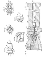
- a fiber optics lens terminal to be formed in accordance with the present invention is generally designated by the reference numeral 10 and shown as a unitary body 12 of light transmitting plastic material generally concentric throughout the length thereof with a central axis 14.
- An exterior flange 16 near the longitudinal center of the body 12 may be characterized as dividing the body into a lens portion 18 and a fiber receiving or ferrule portion 20.
- the periphery of the flange 16, as shown in Figs. 1 and 2 is circular with the exception of a flat 22 on one side thereof.
- the exterior of the lens portion 18 is formed as a tapered section 24 extending from the flange 16 to a cylindrical end section 26 having a radial end face 28.
- a convex aspheric lens surface 30, precisely concentric with the axis 14, is located the base of a cylindrical bore 32 opening through the radial end face 28.
- the focal length of the lens is designated by the dimension f in Fig. 3.
- the ferrule portion 20 is defined by a tapered exterior surface 34 and a generally cylindrical, open-ended fiber receiving socket 36.
- the internal end or bottom of the socket 36 is shown most clearly in Fig. 5 to include an annular floor surface 38 in which a frustoconical recess 40 is formed.
- the recess 40 is precisely centered on the axis 14 and tapers to a circular bottom 42 of a diameter smaller than the outside diameter of an optical fiber (not shown) to be received in the socket 36.
- the diameter of the recess floor 42 will approximate 76 to 127 pm (.0030-.0050 inches) to accommodate a single optical fiber (not shown) having a core size approximating 50 pm or .002 inches and an outside diameter of cladding ranging from about 76 to 127 pm (.003 inches up to .005 inches).
- the recess 40 is dimensioned so that the end of the fiber to be received therein does not touch the bottom 42 of the recess.
- one of two optical fibers to be joined or connected is inserted into the recess 36 and the end thereof guided to a position of precise concentricity with the axis 14 by the frustoconical recess 40.
- the fiber is retained permanently in the ferrule by an appropriate mastic orfiller having an index of refraction preferably substantially identical to that of the optical fiber and of the plastic from which the body 12 is formed.
- the end of the fiber When so received in the socket 36, the end of the fiber will be located precisely at the focal point of the lens 30 so that light emanating from the end of the fiber positioned in the ferrule 20 will be presented as an enlarged collimated image on exiting from the lens surface 30.
- Molding die components of the present invention for shaping the terminal 10 by injection molding of appropriate plastic materials are shown most clearly in Fig. 6 of the drawings.
- such components include a first mold part or "receiver” 50, a second mold part or “lens form” assembly 52 and a third mold part or “socket form” assembly 54.
- the receiver 50 is in the nature of an annular body having a generally cylindrical exterior surface 56 with a radially-projecting mounting flange 58.
- a central mold cavity 60 is defined in a radial wall section 62 located approximately midway along the length of the receiver 50.
- the receiver 50 defines the precise location of the longitudinal axis 14 with which the mold cavity 60 is concentric. More significantly in the context of defining the axis 14, the receiver 50 is provided with precision formed, oppositely diverging frustoconical reference surfaces 64 and 66, respectively. Because the only surfaces of the terminal 10 directly shaped by the receiver cavity 60 are the relatively low tolerance exterior surfaces of the ferrule 20 and the flange 16, precision machining in the receiver 50 is concentrated primarily in the frustoconical reference surfaces 64 and 66.
- the lens form assembly 52 includes a plunger-like body 68, a lens die pin 70, and an end cap 72.
- the body 68 is formed with an enlarged end flange 73 at its outboard end and a frustoconical locating surface 74 at the other or inboard end thereof.
- Critically precision surfaces on the lens form body 68 include the frustoconical locating surface 74 complementing the reference surface 64, peripheral locating and radial end surfaces 76 and 78, respectively, on a circular axially projecting boss 80, and a lens die pin locating bore 82.
- the end cap 72 is secured to the body 68 releasably by screw bolts 84 (only one shown) and defines a central cavity 86 made concentric with the frustoconical locating surface 64 by the peripheral surface 76 on the boss 80.
- the central pin locating bore 82 assures precise concentricity of the pin 70 with the frustoconical locating surface 74.
- An enlarged counterbore 85 extends partially along the length of the pin 70 to facilitate a soldered connection of the pin 70 to the body 68 after final positioning. Removability of the cap 72 is important to facilitate precision machining of the end surface 78 on the boss 80 which defines the radial end face 28 on the terminal 10.
- the die pin 70 projects from a cylindrical body 87, the axial position of which is adjustable by the provision of means to be described in more detail below with reference to Fig. 10 of the drawings.
- the socket form 54 is an assembly of a plunger-like body 88 having a central socket pin die locating bore 90, a gauge block counterbore 92 and an enlarged end flange 93.
- a socket pin die 94 projects through the bore 90 so that the terminal end thereof extends within the receiver cavity 60.
- the body 88 is also formed with a precision machined frustoconical locating surface 96 which complements the reference surface 66 in the receiver 50 in a manner similar to that described above in connection with the lens form assembly 52.
- the terminal end of the pin 94 is provided with molding die surface formations complementing the bottom of the socket 36 described above with reference to Fig. 5 of the drawings.
- the socket die pin 94 is adjustably positionable axially by means which will be described in more detail below.
- the three mold parts 50, 52 and 54 are match machined so that when the three parts are brought together to the position shown in Fig. 6, the axis of the lens die pin 70 and of the socket die pin 94 are concentric within 0.51 pm (.000020 inches).
- Each set of the three mold parts is appropriately marked as a matched set to assure retention of the critical tolerances originally achieved by match machining.
- end clearances C 1 and C 2 are allowed for at the end faces of the end cap 72 and the plunger 88, respectively. While these clearances may result in mold flashing on the flange 16 and the ferrule 20 of the connector terminal 10, slight flashing at these locations is tolerable.
- the clearances C 1 and C 2 may be on the order of 63 to 127 ⁇ m (.0025 inches to .0050 inches).
- the clearance C 1 is near the lower limit of this range whereas the clearance C 2 may be larger.
- the lens form assembly 52 and the socket form assembly 54 are supported in practice for movement on the axis 14 between a closed position with respect to the receiver 50 and an open position which, though not shown in the drawings, involves a sufficient degree of movement of both the lens form assembly 52 and the socket form assembly 54 so that all parts carried by these two assemblies on the axis 14 will clear the receiver 50 to allow movement of the receiver 50 in a direction perpendicular to the axis 14.
- the cavity defining the connector terminal 10 is established whereas in the open condition, the receiver may be moved to a different position for ejection of the molded terminal 10 in a manner which will become apparent from the apparatus to be described.
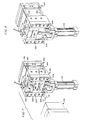
- FIGs. 7 and 8 The general organization of apparatus for supporting and using the mold parts 50, 52 and 54 is shown in Figs. 7 and 8 to include a central frame 100, a reciprocal rear frame 102 and a retractable front frame 104.
- the central frame 100 is provided on its front face, which is visible in Figs. 7, 8 and 9, with a pair of fixed guideways 106 and 108 to support a shuttle 110 for movement between a lower molding position shown in Fig. 7 and an upper ejection position as shown in Fig. 8.
- a reversible piston/cylinder unit 112 is supported from the central frame for advancing the shuttle 110 between the two positions thus depicted respectively in Figs. 7 and 8.
- the overall apparatus defines two molding axes 14 and 14'.
- the plane defined by these parallel axes 14 and 14' is, moreover, a horizontal plane containing the longitudinal center line of the three frames 100, 102 and 104.
- the frames carry a full complement of working components on each of the two axes including a full set of the three mold part assemblies described above with reference to Fig. 6.
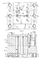
- a longitudinal cross section throughout the three frame members 100, 102 and 104 on the plane containing the two axes 14 and 14' is partially illustrated to show all components on the axis 14, such components being duplicated in practice on the axis 14'.
- the receiver 50 is shown supported in the shuttle 110 and retained in place by a shuttle backplate 114 in abutment with the mounting flange 58 on the receiver 50.
- the passageway for introducing plastic material under injection pressures into the mold cavity 60 is illustrated as including a central sprue 116 extending from a concavity 118 at the outboard end face of the front frame 104 to a shuttle runner 120 in communication with a receiver runner 122 which opens to the mold cavity 60, specifically at the flat 22 on the circular flange 116 of the connector terminal. 10 to be formed.
- the opening of the receiver runner 122 into the cavity 60 thus constitutes the only non- molding portion of internal surfaces defined by the cavity 60.
- the lens form assembly 52 is shown in Fig. 10 to be carried by the front frame 104.
- the body 68 of the assembly 52 is located in a face plate 123 and secured by an apertured inset plate 124 positioned to be in abutment with the end flange 73.
- the assembly 52 is shown more completely than in Fig. 6 as described above.
- the cylindrical mounting body 87, from which the lens die pin 70 projects, is captured by abutment against the face of a micrometer screw 126 under force developed by a screw bolt 128.
- the micrometer screw 126 is threadably received within an internally threaded end bore 130 in the plunger body 68 and is capable of being secured in a finally adjusted position by a set screw 132.
- a dowel pin 134 rides in an axial slot 136 in the faceplate 123 forming part of the front frame 104 to retain the angular orientation of the assembly 52.
- This arrangement enables adjustment of the precise axial position of the pin 70 relative to the body 68 and, in particular, the conical locating surface 74 thereon. Once the position is established using the micrometer screw 126, the location of the pin is secured by soldering, given the facility of the counterbore 85 described above with reference to Fig. 6. It is contemplated that a system of abutment gauge blocks and shims may be used with equal or greater accuracy to axially position the lens die pin 70 in the body 68.
- a drive plunger 140 Situated behind the lens form assembly 52 in the context of its movement toward the closed position in the receiver 50, is a drive plunger 140 in abutment at an inboard end 142 with the body 68 and engaged at its other or outboard end 144 exclusively by a ball 146 positioned on the axis 14 by a spring plunger 148.
- the drive plunger 140 is formed with a head 150 at its outboard end adapted to mount an 0-ring 152.
- the head 150 of the drive plunger 140 and the spring plunger 148 are slidably received within a cup-like receptacle 154 to be retained therein by an annular cap 156 through which the body of the drive plunger 140 projects.
- the receptacle is captured in the front frame member 104 between the face plate 123 thereof and an outboard end plate 158.
- a Belleville spring washer set 160 is included in the receptacle 154 and effective between the bottom or outboard end thereof and the spring plunger 148.
- the spring washer 160 imposes an axial bias through the spring plunger 148, the ball 146, the drive plunger 140 to the body 68 of the lens form assembly 52 so that these parts are seized axially between the spring washer 160 and the inset plate 124 of the front frame member 104.
- the spring washer set 160 functions to limit the axial force by which the frustoconical reference surfaces on the assembly 52 may be advanced against the frustoconical abutment surface 64 on the receiver 50 as the frame member 104 is moved against the central frame 100.
- each of the plunger-like body 68 of the lens form assembly 52, the drive plunger 140, and the spring plunger 148 are supported in the frame 104 with radial clearance in a manner such that the axial location of the lens form assembly 52 is not affected in any way by precise axial alignment of the frame 104 with the axis 14, the location and orientation of which is established exclusively by the receiver 50.
- movement of the locating surface 74 on the lens form assembly 52 into the frustoconical reference surface 64 of the receiver 50 is exclusively under an axial closing force limited in its magnitude by the Belleville washer set 160.
- the socket form assembly 54 is carried by the rearframe 102 in a manner substantially the same as the lens form assembly 52 is carried by the front frame 104.
- the body 88 of the assembly 54 projects through a bore 162 in a body plate 164 of the frame 102 with the end flange 93 of the body 88 in abutment with the base of a first counterbore 166 having a radial slot 168 to receive a dowel pin 170 to maintain the angular orientation of the assembly 54 on the axis 14.
- a cup-like receptacle 172 identical to the receptacle 154, is received in a second counterbore 174 closed by an outboard end plate 176 forming part of the rear frame 102.
- a drive plunger 178, a ball 180, a spring plunger 182 and a Belleville washer set 184 are contained within the receptacle 172 in the same manner as the corresponding components are supported in the receptacle 152. Also, the body 88, plunger 178, and spring plunger 182 are again supported with radial clearance so that forces ultimately advancing the frustoconical locating surface 96 at the inboard end of the body 88 are isolated exclusively to axial forces transmitted by the Belleville washer spring set 184 and the ball 180.
- the socket die pin 94 like the lens die pin 70, projects from a cylindrical body 186 received in the counterbore 92. Axial positioning of the socket die pin 94 is established by a cylindrical gauge block 188 extending between the outboard end of the cylindrical body 186 and the inboard end or face of the drive plunger 178. Such an arrangement facilitates the use of shims or precisely dimensioned gauge blocks of .varying specific lengths to enable accurate axial positioning of the socket die pin 94 in relation to the locating surface 96 on the body 88. As in the case of the lens die pin 70, the socket die pin 94 may be soldered to the body 88 once its precise final position has been established.
- the rear frame 102 is supported from the central frame 100 by four guide rods 190 anchored in a bed plate 192 of the central frame 100.
- the rear frame 102 is reciprocable on the guide rods 190 between an advanced working position as shown in Fig. 7 and a retracted position shown in Fig. 8.
- the advanced working position is established by abutment of the inboard face of the body plate 164 with the rear face of the bed plate 192 on the central frame 100.
- the retracted position is established by four shoulder bolts 194 secured in the bed plate 192, each having a head 196 operative in a counterbore 198 to allow movement represented by the double-sided arrow 200 in Fig. 11.
- the rear frame 102 supports a plurality of locating and ejection pins for cooperation with the shuttle 110 both in its molding position as shown in Fig. 7 and in its ejection position as shown in Fig. 8. Specifically, a pair of part ejection pins 202 and 204 are supported from the rear frame 102 in a position to project into the receiver mold cavity 60 to eject the part 10 from the receiver 50 when the shuttle 110 is positioned in its upper position. A sprue ejection pin 206 is similarly supported from the rear frame 102.
- the final positioning of the shuttle 110 in both the molding position and in the elevated ejection position is effected by a pair of locator pins 208 and 210 adapted to project into one of two pairs of vertically spaced locator bores 212 and 214 in the shuttle 110.
- the center-to-center spacing of the pairs of bores 212 and 214 is equal to the distance of shuttle travel between the molding position of Fig. 7 and the ejection position of Fig. 8.
- the front frame 104 is supported for axial movement against the front face of the center frame 100.
- the front face of the guide rails 106 and 108 are each provided with two essentially cylindrical sockets 216 and 218 as well as with a frustoconical pocket 220.
- Complementary projections on the inboard face 222 of the front frame 104 engage in the recesses 216, 218 and 220 to establish the final position of the front frame 104 against the center frame 100.
- the projections on the front face which engage the cylindrical recesses 216 and 218 are not shown in the drawings, one of the frustoconical recesses 220 is shown in Fig. 10 together with a complementing projection 224 on' the front frame 104.
- the front and rear frames are retracted away from the shuttle 110, and the piston/cylinder unit 112 actuated to move the shuttle upwardly to the injection position shown in Fig. 8.
- the rear frame 102 is advanced again toward the central frame 100 so that the ejection pins 204 and 206 engage the rear of the mold cavity 60 as well as portions of plastic formed by the sprue 116 and the runners 120 and 122.
- the rear frame 102 is again retracted, the shuttle 110 lowered, and the cylce repeated.
Landscapes
- Physics & Mathematics (AREA)
- Engineering & Computer Science (AREA)
- Manufacturing & Machinery (AREA)
- Mechanical Engineering (AREA)
- General Physics & Mathematics (AREA)
- Optics & Photonics (AREA)
- Health & Medical Sciences (AREA)
- Ophthalmology & Optometry (AREA)
- Moulds For Moulding Plastics Or The Like (AREA)
- Mechanical Coupling Of Light Guides (AREA)
- Injection Moulding Of Plastics Or The Like (AREA)
- Optical Couplings Of Light Guides (AREA)
Claims (22)
Priority Applications (1)
| Application Number | Priority Date | Filing Date | Title |
|---|---|---|---|
| AT83110732T ATE29236T1 (de) | 1982-11-02 | 1983-10-27 | Verfahren und vorrichtung zur herstellung eines optischen verbindungsstueckes. |
Applications Claiming Priority (2)
| Application Number | Priority Date | Filing Date | Title |
|---|---|---|---|
| US06/438,586 US4531702A (en) | 1982-11-02 | 1982-11-02 | Injection mold for forming optical fiber connector |
| US438586 | 1995-05-08 |
Publications (2)
| Publication Number | Publication Date |
|---|---|
| EP0110140A1 EP0110140A1 (de) | 1984-06-13 |
| EP0110140B1 true EP0110140B1 (de) | 1987-09-02 |
Family
ID=23741212
Family Applications (1)
| Application Number | Title | Priority Date | Filing Date |
|---|---|---|---|
| EP83110732A Expired EP0110140B1 (de) | 1982-11-02 | 1983-10-27 | Verfahren und Vorrichtung zur Herstellung eines optischen Verbindungsstückes |
Country Status (8)
| Country | Link |
|---|---|
| US (1) | US4531702A (de) |
| EP (1) | EP0110140B1 (de) |
| JP (1) | JPH0639114B2 (de) |
| AT (1) | ATE29236T1 (de) |
| AU (1) | AU567517B2 (de) |
| CA (1) | CA1220908A (de) |
| DE (1) | DE3373290D1 (de) |
| IE (1) | IE54692B1 (de) |
Families Citing this family (32)
| Publication number | Priority date | Publication date | Assignee | Title |
|---|---|---|---|---|
| US4689005A (en) * | 1982-11-02 | 1987-08-25 | Polaroid Corporation | Molding apparatus |
| US5074771A (en) * | 1982-12-27 | 1991-12-24 | Amp Incorporated | Dual injection molding apparatus |
| US4659173A (en) * | 1983-12-15 | 1987-04-21 | Rmc, Inc. | Microtomy specimen block having a fiber optic transmission medium therein and method of forming the same |
| CA1245818A (en) * | 1984-05-03 | 1988-12-06 | Polaroid Corporation | Molding apparatus |
| US4655274A (en) * | 1984-10-26 | 1987-04-07 | Ube Industries, Ltd. | Horizontal mold clamping and vertical injection type die cast machine |
| US4953938A (en) * | 1985-10-28 | 1990-09-04 | Gte Laboratories Incorporated | Optical fiber expanded beam connector |
| US4790971A (en) * | 1986-07-09 | 1988-12-13 | Trantek Inc. | Shuttle transfer system |
| US4732726A (en) * | 1986-09-18 | 1988-03-22 | E. W. Mold & Tool Co., Inc. | Injection mold with insert transfer means and method |
| DE3734118A1 (de) * | 1987-10-09 | 1989-04-20 | Festo Kg | Aus zwei voneinander trennbaren formhaelften bestehende negativform |
| US5127820A (en) * | 1989-11-07 | 1992-07-07 | Bell Communications Research, Inc. | High-precision adjustable injection molding of single-mode fiber optic connectors |
| US5034170A (en) * | 1989-11-07 | 1991-07-23 | Bell Communications Research, Inc. | High-precision adjustable injection molding of single-mode fiber optic connectors |
| JP3088779B2 (ja) * | 1991-05-24 | 2000-09-18 | 古河電気工業株式会社 | 光コネクタ用フェルールの成形金型 |
| US5542255A (en) * | 1994-05-04 | 1996-08-06 | Minnesota Valley Engineering, Inc. | High temperature resistant thermal insulation for cryogenic tanks |
| TW260753B (de) * | 1992-12-03 | 1995-10-21 | Du Pont | |
| US5352398A (en) * | 1993-05-06 | 1994-10-04 | Eastman Kodak Company | Apparatus and method for attaching a cap to a mold core |
| US6039553A (en) | 1998-12-02 | 2000-03-21 | 3M Innovative Properties Company | Apparatus for molding light extraction structures onto a light guide |
| US6494706B2 (en) * | 2001-04-18 | 2002-12-17 | L. L. Culmat, Lp | Optical attenuator mold |
| US6895654B2 (en) * | 2001-07-06 | 2005-05-24 | Ksaria Corporation | Apparatus and method for attaching a component to a fiber |
| US20030062637A1 (en) * | 2001-10-02 | 2003-04-03 | Alden John C. | Method and apparatus for recoating optical fiber |
| US20030062122A1 (en) * | 2001-10-02 | 2003-04-03 | Keane Richard J. | Optical fiber processing system and method |
| US20060145369A1 (en) * | 2004-12-30 | 2006-07-06 | Lawton Bruce E | Non-optical multi-piece core assembly for rapid tool change |
| CN100498398C (zh) * | 2005-07-21 | 2009-06-10 | 中国科学院半导体研究所 | 光纤转接器结构 |
| US20070200673A1 (en) * | 2006-02-13 | 2007-08-30 | Godwin Bryan W | Apparatus and Method for Controlling and Monitoring Access to a Storage Container |
| US7686224B2 (en) * | 2006-08-30 | 2010-03-30 | Coherent, Inc. | Lensed dual diode-laser bar package |
| US7809230B2 (en) * | 2007-09-25 | 2010-10-05 | Ksaria Corporation | Apparatus for shaping the end of an optical fiber |
| CN101468501A (zh) * | 2007-12-27 | 2009-07-01 | 鸿富锦精密工业(深圳)有限公司 | 模仁高度可调整的模具 |
| CN101468870A (zh) * | 2007-12-29 | 2009-07-01 | 鸿富锦精密工业(深圳)有限公司 | 模造玻璃镜片的模具及模造玻璃镜片的方法 |
| TW201136744A (en) * | 2010-04-20 | 2011-11-01 | Hon Hai Prec Ind Co Ltd | Mold for making optical fiber connector and method of making same |
| US8254738B2 (en) | 2010-08-27 | 2012-08-28 | Ksaria Corporation | Methods and systems for efficient installation of cables in watercraft |
| US9239428B2 (en) | 2011-09-28 | 2016-01-19 | Ksaria Corporation | Epoxy dispensing system and dispensing tip used therewith |
| HUP1800439A2 (hu) * | 2018-12-20 | 2020-06-29 | Equip Test Kft | Csatlakozószerkezet optikai vezetékek csatlakoztatására, valamint krimpelõ eszköz és kinyomó eszköz ahhoz |
| CN121123721B (zh) * | 2025-11-14 | 2026-01-16 | 深圳市天麟精密模具有限公司 | 一种压接式接口连接器的结构控制件及制造工艺 |
Citations (1)
| Publication number | Priority date | Publication date | Assignee | Title |
|---|---|---|---|---|
| US3942755A (en) * | 1974-10-09 | 1976-03-09 | Pioneer Plastic Containers Limited | Moulds for use on injection moulding machines |
Family Cites Families (13)
| Publication number | Priority date | Publication date | Assignee | Title |
|---|---|---|---|---|
| US3647337A (en) * | 1969-06-17 | 1972-03-07 | Gen Motors Corp | Precision molding apparatus |
| US3999841A (en) * | 1974-08-19 | 1976-12-28 | Gte Laboratories Incorporated | Method for forming an optical fiber connector |
| CA1094369A (en) * | 1975-11-11 | 1981-01-27 | Peter K. Runge | Optical fiber connector and method of making |
| GB1499359A (en) * | 1975-12-23 | 1978-02-01 | Standard Telephones Cables Ltd | Optical fibre connectors |
| US4087158A (en) * | 1976-12-06 | 1978-05-02 | The United States Of America As Represented By The Secretary Of The Navy | Low-loss single filament fiber optic connector with three concentric tapered members for each filaments |
| US4173389A (en) * | 1977-09-28 | 1979-11-06 | Bell Telephone Laboratories, Incorporated | Molded optical fiber connector |
| JPS5561351A (en) * | 1978-10-30 | 1980-05-09 | Toyota Motor Corp | Casting mold device |
| US4254065A (en) * | 1979-04-04 | 1981-03-03 | Ratkowski Donald J | Injection molding of contact lenses |
| US4327964A (en) * | 1979-12-20 | 1982-05-04 | Texas Instruments Incorporated | Snap-action fiber optic connector |
| CA1144794A (en) * | 1980-01-17 | 1983-04-19 | W. John Carlsen | Optical fiber connectors |
| US4291941A (en) * | 1980-02-04 | 1981-09-29 | The Deutsch Company Electronic Components Division | Optical fiber connector |
| JPS56155911A (en) * | 1980-05-02 | 1981-12-02 | Nec Corp | Manufacture of optical mold connector |
| EP0053483B1 (de) * | 1980-11-28 | 1985-10-02 | Kabushiki Kaisha Toshiba | Verfahren zur Herstellung eines Moduls für ein fiberoptisches Nachrichtensystem |
-
1982
- 1982-11-02 US US06/438,586 patent/US4531702A/en not_active Expired - Lifetime
-
1983
- 1983-10-27 DE DE8383110732T patent/DE3373290D1/de not_active Expired
- 1983-10-27 AT AT83110732T patent/ATE29236T1/de not_active IP Right Cessation
- 1983-10-27 EP EP83110732A patent/EP0110140B1/de not_active Expired
- 1983-10-31 CA CA000440080A patent/CA1220908A/en not_active Expired
- 1983-11-01 JP JP58203794A patent/JPH0639114B2/ja not_active Expired - Lifetime
- 1983-11-01 AU AU20874/83A patent/AU567517B2/en not_active Ceased
- 1983-11-01 IE IE2554/83A patent/IE54692B1/en not_active IP Right Cessation
Patent Citations (1)
| Publication number | Priority date | Publication date | Assignee | Title |
|---|---|---|---|---|
| US3942755A (en) * | 1974-10-09 | 1976-03-09 | Pioneer Plastic Containers Limited | Moulds for use on injection moulding machines |
Also Published As
| Publication number | Publication date |
|---|---|
| JPH0639114B2 (ja) | 1994-05-25 |
| IE832554L (en) | 1984-05-02 |
| EP0110140A1 (de) | 1984-06-13 |
| CA1220908A (en) | 1987-04-28 |
| DE3373290D1 (en) | 1987-10-08 |
| ATE29236T1 (de) | 1987-09-15 |
| AU2087483A (en) | 1984-05-10 |
| US4531702A (en) | 1985-07-30 |
| IE54692B1 (en) | 1990-01-03 |
| JPS5997111A (ja) | 1984-06-04 |
| AU567517B2 (en) | 1987-11-26 |
Similar Documents
| Publication | Publication Date | Title |
|---|---|---|
| US4531702A (en) | Injection mold for forming optical fiber connector | |
| US4925267A (en) | Structure and fabrication of components for connecting optical fibers | |
| US5560939A (en) | Mold assembly comprising a sliding mold insert adapted for automated insertion and removal | |
| US4330171A (en) | Optical-fiber connector, centering device and method of manufacture of said connector | |
| US5587116A (en) | Process for injection molding optical ferrules | |
| EP0393183A1 (de) | Optischer stecker mit einem justiersteckteil aus kunststoff. | |
| US5034170A (en) | High-precision adjustable injection molding of single-mode fiber optic connectors | |
| US5862281A (en) | Optical fiber connectors | |
| EP0672264B1 (de) | Spritzgegossener optischer steckerstift sowie vorrichtung und herstellungsverfahren dafür | |
| US4689005A (en) | Molding apparatus | |
| HU188789B (en) | Switching device for the optical fibers and method for making this switching device | |
| US4814118A (en) | Method of molding a connector for optical fibers | |
| US4689184A (en) | Method for forming an optical connector | |
| EP1146370A2 (de) | Verfahren zur Herstellung eines Steckerstifts aus Kunststoff für eine optische Steckverbindung | |
| EP0160312A2 (de) | Präzisionsformgerät zum Formen eines Kunststoffbauteils | |
| US5127820A (en) | High-precision adjustable injection molding of single-mode fiber optic connectors | |
| JPH06278141A (ja) | プラスチック成形装置 | |
| JP3706169B2 (ja) | 射出成形用金型 | |
| JPH0415606A (ja) | 光コネクタ用セラミックフェルールの射出成形用金型 | |
| JP3152601B2 (ja) | ディスク射出成形金型の固定側と可動側の円盤キャビティプレートの整列案内装置 | |
| US20060093704A1 (en) | Optical component molding apparatus | |
| US7402032B2 (en) | Mold apparatus and manufacturing method for the mold apparatus | |
| JPH0530608B2 (de) | ||
| CN215575864U (zh) | 一种镜头模组 | |
| JPH0416303A (ja) | セラミック製品の射出成形用金型装置 |
Legal Events
| Date | Code | Title | Description |
|---|---|---|---|
| PUAI | Public reference made under article 153(3) epc to a published international application that has entered the european phase |
Free format text: ORIGINAL CODE: 0009012 |
|
| AK | Designated contracting states |
Designated state(s): AT BE CH DE FR GB IT LI NL |
|
| 17P | Request for examination filed |
Effective date: 19840710 |
|
| GRAA | (expected) grant |
Free format text: ORIGINAL CODE: 0009210 |
|
| AK | Designated contracting states |
Kind code of ref document: B1 Designated state(s): AT BE CH DE FR GB IT LI NL |
|
| REF | Corresponds to: |
Ref document number: 29236 Country of ref document: AT Date of ref document: 19870915 Kind code of ref document: T |
|
| REF | Corresponds to: |
Ref document number: 3373290 Country of ref document: DE Date of ref document: 19871008 |
|
| ET | Fr: translation filed | ||
| ITF | It: translation for a ep patent filed | ||
| PLBE | No opposition filed within time limit |
Free format text: ORIGINAL CODE: 0009261 |
|
| STAA | Information on the status of an ep patent application or granted ep patent |
Free format text: STATUS: NO OPPOSITION FILED WITHIN TIME LIMIT |
|
| 26N | No opposition filed | ||
| ITTA | It: last paid annual fee | ||
| PGFP | Annual fee paid to national office [announced via postgrant information from national office to epo] |
Ref country code: FR Payment date: 19970910 Year of fee payment: 15 |
|
| PGFP | Annual fee paid to national office [announced via postgrant information from national office to epo] |
Ref country code: BE Payment date: 19970916 Year of fee payment: 15 Ref country code: AT Payment date: 19970916 Year of fee payment: 15 |
|
| PGFP | Annual fee paid to national office [announced via postgrant information from national office to epo] |
Ref country code: GB Payment date: 19970918 Year of fee payment: 15 |
|
| PGFP | Annual fee paid to national office [announced via postgrant information from national office to epo] |
Ref country code: DE Payment date: 19970922 Year of fee payment: 15 |
|
| PGFP | Annual fee paid to national office [announced via postgrant information from national office to epo] |
Ref country code: NL Payment date: 19970923 Year of fee payment: 15 |
|
| PGFP | Annual fee paid to national office [announced via postgrant information from national office to epo] |
Ref country code: CH Payment date: 19971002 Year of fee payment: 15 |
|
| PG25 | Lapsed in a contracting state [announced via postgrant information from national office to epo] |
Ref country code: GB Free format text: LAPSE BECAUSE OF NON-PAYMENT OF DUE FEES Effective date: 19981027 Ref country code: AT Free format text: LAPSE BECAUSE OF NON-PAYMENT OF DUE FEES Effective date: 19981027 |
|
| PG25 | Lapsed in a contracting state [announced via postgrant information from national office to epo] |
Ref country code: LI Free format text: LAPSE BECAUSE OF NON-PAYMENT OF DUE FEES Effective date: 19981031 Ref country code: CH Free format text: LAPSE BECAUSE OF NON-PAYMENT OF DUE FEES Effective date: 19981031 Ref country code: BE Free format text: LAPSE BECAUSE OF NON-PAYMENT OF DUE FEES Effective date: 19981031 |
|
| BERE | Be: lapsed |
Owner name: POLAROID CORP. Effective date: 19981031 |
|
| PG25 | Lapsed in a contracting state [announced via postgrant information from national office to epo] |
Ref country code: NL Free format text: LAPSE BECAUSE OF NON-PAYMENT OF DUE FEES Effective date: 19990501 |
|
| REG | Reference to a national code |
Ref country code: CH Ref legal event code: PL |
|
| GBPC | Gb: european patent ceased through non-payment of renewal fee |
Effective date: 19981027 |
|
| PG25 | Lapsed in a contracting state [announced via postgrant information from national office to epo] |
Ref country code: FR Free format text: LAPSE BECAUSE OF NON-PAYMENT OF DUE FEES Effective date: 19990630 |
|
| NLV4 | Nl: lapsed or anulled due to non-payment of the annual fee |
Effective date: 19990501 |
|
| REG | Reference to a national code |
Ref country code: FR Ref legal event code: ST |
|
| PG25 | Lapsed in a contracting state [announced via postgrant information from national office to epo] |
Ref country code: DE Free format text: LAPSE BECAUSE OF NON-PAYMENT OF DUE FEES Effective date: 19990803 |