EP0110185A1 - Verfahren und Vorrichtung zur Erzeugung einer Gradationskorrekturfunktion - Google Patents
Verfahren und Vorrichtung zur Erzeugung einer Gradationskorrekturfunktion Download PDFInfo
- Publication number
- EP0110185A1 EP0110185A1 EP83110988A EP83110988A EP0110185A1 EP 0110185 A1 EP0110185 A1 EP 0110185A1 EP 83110988 A EP83110988 A EP 83110988A EP 83110988 A EP83110988 A EP 83110988A EP 0110185 A1 EP0110185 A1 EP 0110185A1
- Authority
- EP
- European Patent Office
- Prior art keywords
- curve
- gradation correction
- radiation image
- electric signal
- radiation
- Prior art date
- Legal status (The legal status is an assumption and is not a legal conclusion. Google has not performed a legal analysis and makes no representation as to the accuracy of the status listed.)
- Granted
Links
- 238000012937 correction Methods 0.000 title claims abstract description 52
- 238000000034 method Methods 0.000 title claims description 23
- 230000005855 radiation Effects 0.000 claims abstract description 54
- OAICVXFJPJFONN-UHFFFAOYSA-N Phosphorus Chemical compound [P] OAICVXFJPJFONN-UHFFFAOYSA-N 0.000 claims abstract description 41
- 230000004936 stimulating effect Effects 0.000 claims abstract description 14
- 239000000463 material Substances 0.000 claims description 14
- 238000012545 processing Methods 0.000 claims description 13
- 230000003287 optical effect Effects 0.000 claims description 12
- 230000000638 stimulation Effects 0.000 claims description 2
- 238000009826 distribution Methods 0.000 description 13
- 238000006243 chemical reaction Methods 0.000 description 7
- 229910052771 Terbium Inorganic materials 0.000 description 3
- 229910052788 barium Inorganic materials 0.000 description 3
- DSAJWYNOEDNPEQ-UHFFFAOYSA-N barium atom Chemical compound [Ba] DSAJWYNOEDNPEQ-UHFFFAOYSA-N 0.000 description 3
- 238000013500 data storage Methods 0.000 description 3
- 230000003247 decreasing effect Effects 0.000 description 3
- 238000003672 processing method Methods 0.000 description 3
- 238000002601 radiography Methods 0.000 description 3
- 229910052684 Cerium Inorganic materials 0.000 description 2
- 229910052693 Europium Inorganic materials 0.000 description 2
- 229910052784 alkaline earth metal Inorganic materials 0.000 description 2
- 150000001342 alkaline earth metals Chemical class 0.000 description 2
- 229910052793 cadmium Inorganic materials 0.000 description 2
- 229910052791 calcium Inorganic materials 0.000 description 2
- 239000000975 dye Substances 0.000 description 2
- 229910052749 magnesium Inorganic materials 0.000 description 2
- 229910052761 rare earth metal Inorganic materials 0.000 description 2
- 229910052712 strontium Inorganic materials 0.000 description 2
- 229910052725 zinc Inorganic materials 0.000 description 2
- 229910052691 Erbium Inorganic materials 0.000 description 1
- 229910052688 Gadolinium Inorganic materials 0.000 description 1
- 229910052689 Holmium Inorganic materials 0.000 description 1
- 229910052779 Neodymium Inorganic materials 0.000 description 1
- 229910052775 Thulium Inorganic materials 0.000 description 1
- 229910052769 Ytterbium Inorganic materials 0.000 description 1
- AEEAZFQPYUMBPY-UHFFFAOYSA-N [I].[W] Chemical compound [I].[W] AEEAZFQPYUMBPY-UHFFFAOYSA-N 0.000 description 1
- 238000013459 approach Methods 0.000 description 1
- 229910052797 bismuth Inorganic materials 0.000 description 1
- 238000007796 conventional method Methods 0.000 description 1
- 238000010586 diagram Methods 0.000 description 1
- 230000008030 elimination Effects 0.000 description 1
- 238000003379 elimination reaction Methods 0.000 description 1
- 229910052740 iodine Inorganic materials 0.000 description 1
- 229910052746 lanthanum Inorganic materials 0.000 description 1
- 229910052745 lead Inorganic materials 0.000 description 1
- 210000004072 lung Anatomy 0.000 description 1
- 229910052748 manganese Inorganic materials 0.000 description 1
- 229910001509 metal bromide Inorganic materials 0.000 description 1
- 229910001510 metal chloride Inorganic materials 0.000 description 1
- 229910001512 metal fluoride Inorganic materials 0.000 description 1
- 229910001511 metal iodide Inorganic materials 0.000 description 1
- 239000000049 pigment Substances 0.000 description 1
- 150000002910 rare earth metals Chemical class 0.000 description 1
- PYWVYCXTNDRMGF-UHFFFAOYSA-N rhodamine B Chemical compound [Cl-].C=12C=CC(=[N+](CC)CC)C=C2OC2=CC(N(CC)CC)=CC=C2C=1C1=CC=CC=C1C(O)=O PYWVYCXTNDRMGF-UHFFFAOYSA-N 0.000 description 1
- 229940043267 rhodamine b Drugs 0.000 description 1
- 229910052709 silver Inorganic materials 0.000 description 1
- 239000004332 silver Substances 0.000 description 1
- -1 silver halide Chemical class 0.000 description 1
- 229910052716 thallium Inorganic materials 0.000 description 1
- 229910052727 yttrium Inorganic materials 0.000 description 1
Images
Classifications
-
- H—ELECTRICITY
- H04—ELECTRIC COMMUNICATION TECHNIQUE
- H04N—PICTORIAL COMMUNICATION, e.g. TELEVISION
- H04N1/00—Scanning, transmission or reproduction of documents or the like, e.g. facsimile transmission; Details thereof
- H04N1/40—Picture signal circuits
- H04N1/407—Control or modification of tonal gradation or of extreme levels, e.g. background level
- H04N1/4072—Control or modification of tonal gradation or of extreme levels, e.g. background level dependent on the contents of the original
-
- G—PHYSICS
- G01—MEASURING; TESTING
- G01T—MEASUREMENT OF NUCLEAR OR X-RADIATION
- G01T1/00—Measuring X-radiation, gamma radiation, corpuscular radiation, or cosmic radiation
- G01T1/16—Measuring radiation intensity
- G01T1/20—Measuring radiation intensity with scintillation detectors
- G01T1/2012—Measuring radiation intensity with scintillation detectors using stimulable phosphors, e.g. stimulable phosphor sheets
- G01T1/2014—Reading out of stimulable sheets, e.g. latent image
-
- G—PHYSICS
- G03—PHOTOGRAPHY; CINEMATOGRAPHY; ANALOGOUS TECHNIQUES USING WAVES OTHER THAN OPTICAL WAVES; ELECTROGRAPHY; HOLOGRAPHY
- G03B—APPARATUS OR ARRANGEMENTS FOR TAKING PHOTOGRAPHS OR FOR PROJECTING OR VIEWING THEM; APPARATUS OR ARRANGEMENTS EMPLOYING ANALOGOUS TECHNIQUES USING WAVES OTHER THAN OPTICAL WAVES; ACCESSORIES THEREFOR
- G03B42/00—Obtaining records using waves other than optical waves; Visualisation of such records by using optical means
- G03B42/02—Obtaining records using waves other than optical waves; Visualisation of such records by using optical means using X-rays
-
- H—ELECTRICITY
- H04—ELECTRIC COMMUNICATION TECHNIQUE
- H04N—PICTORIAL COMMUNICATION, e.g. TELEVISION
- H04N1/00—Scanning, transmission or reproduction of documents or the like, e.g. facsimile transmission; Details thereof
- H04N1/40—Picture signal circuits
- H04N1/407—Control or modification of tonal gradation or of extreme levels, e.g. background level
Definitions
- This invention relates to a method of creating a curve for correcting the gradation of a radiation image used for viewing, particularly for diagnostic purposes, and an apparatus for carrying out the method.
- This invention particularly relates to a method of creating a gradation correction curve used for conducting intermediate processing in a radiation image system wherein a radiation image is read out from a stimulable phosphor carrying the radiation image stored therein and reproduced into a visible image, and an apparatus for carrying out the method.
- a novel radiation image system for recording a radiation image in a stimulable phosphor, reading out the radiation image from the stimulable phosphor, and reproducing a visible radiation image on a recording material such as a photographic film is disclosed, for example, in U.S. Patent No. 4,258,264.
- This system comprises the steps of having a radiation passing through an object absorbed by a stimulable phosphor, stimulating the phosphor by light energy to cause the phosphor to emit the radiation energy stored therein as light, detecting the emitted light and converting it to an electric signal used for reproducing a visible image.
- This radiation image system using the stimulable phosphor is advantageous over the conventional radiography using a silver halide photographic material in that the image can be recorded over a very wide range of radiation exposure. This is very advantageous in practical use.
- radiographs should preferably have both a wide exposure latitude and high image quality suitable for viewing, particularly for diagnostic purposes.
- the conventional radiography is designed so as to satisfy all the required conditions to some extent, the range of recording density or the ability to record various levels of information is insufficient (one approach to the elimination of this problem is the aforesaid radiation image system using the stimulable phosphor), and the image quality is not sufficient for viewing, particularly for diagnostic purposes.
- neither of these requirements is completely satisfied.
- a density-to-electric signal conversion pattern i.e. the gradation correction pattern
- a signal conversion processing is conducted on an electric signal obtained by reading out the radiation image from a stimulable phosphor and converting it photoelectrically, thereby to conduct the gradation processing.
- the aforesaid gradation correction pattern is normably called the gradation correction curve.
- the primary object of the present invention is to provide a method of creating a gradation correction curve, which creates many gradation correction curves according to various objects and various purposes by converting a basic gradation correction pattern.
- Another object of the present invention is to provide a method of creating a gradation correction curve, which quickly creates many desired gradation correction curves by use of a data storage means having a small storage capacity.
- the specific object of the present invention is to provide an apparatus for carrying out the method.
- the present invention provides a-method of creating a curve for correcting the gradation of a radiation image recorded in a stimulable phosphor in a pattern of radiation energy stored therein wherein said stimulable phosphor is scanned with stimulating rays to cause it to emit light in an amount proportional to the level of the radiation energy stored, the emitted light is detected and converted to an electric signal having a level corresponding to the emitted amount of the light, and a visible image corresponding to said radiation image is reproduced on a recording material by use of the electric signal, the method of creating a curve for correcting the gradation of the radiation image comprising the steps of:
- many desired gradation correction curves can be obtained from one of several (about ten) basic gradation correction curves by rotating and/or parallel-shifting the basic gradation correction curve according to the object, the radiation source voltage, the purpose, or the like. Since it is sufficient that only the data on the basic gradation correction curves be stored in a data storage means such as an electronic computer, the method of the present invention is advantageous in that the size of the required data storage means can be reduced. The method is advantageous also in that processing can be conducted quickly.
- gradation correction curve is meant a curve representing the relationship between the optical density of a reproduced visible image and the level of the electric signal obtained by photoelectrically converting the brightness of the object.
- the gradation correction curve is of the type usually used in the field image processing.
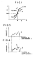
- Figure 1 is an explanatory graph showing the rotation of a gradation correction curve conducted according to the method of the present invention.
- rotation is meant that, as shown in Figure 1, a new curve is created from a reference curve by shifting the points on the reference curve in the x coordinate axis direction or in the y coordinate axis direction by a distance proportional to the distance from the center of rotation (O) on the reference curve to the x coordinates or to the y coordinates of the respective points.
- the rotation or the parallel-shift also embraces the case wherein the amount of the rotation or the parallel-shift is zero.
- the stimulable phosphor referred to in this invention means a phosphor which is able to store radiation energy upon exposure thereof to a high energy radiation and then emits light according to the stored energy upon optical stimulation.
- the high energy radiation referred to here includes X-rays, a-rays, S-rays, y-rays, neutron rays, ultraviolet rays and the like.
- a light beam having high directivity like a laser beam is used as the light beam.
- a light beam having a wavelength within the range of 500 to 800nm, preferably within the range of 600 to 700nm is preferred. If a cut filter which cuts the light having a wavelength beyond the above range is used together with a stimulating ray source, a stimulating ray source having a wavelength distribution beyond said range can be used.
- the stimulating ray source which emits the light having the above mentioned wavelength region
- a Kr-laser (647nm), a He-Ne laser (633nm), various kinds of light emitting diodes, a rhodamine B dye laser or the like
- a tungsten iodine lamp having a wide wavelength distribution covering near ultraviolet rays, visible light and infrared rays can be used if combined with a cut filter which only transmits light of the wavelength within the range of 500 to 800nm or 600-700nm.
- the S-N ratio would be markedly lowered if the stimulating rays should enter the photodetector. Therefore, in order to prevent the lowering of the S/N ratio, it is desirable to make the wavelength distribution of the stimulating rays different from and far apart from the wavelength distribution of the light emitted from the stimulable phosphor.
- the stimulable phosphor is desired to emit light having a wavelength within the range of 300 to 500nm.
- rare earth element activated alkaline earth metal fluorohalide phosphor is preferred.
- This phosphor is, as shown in DE-OS No. 29 28 245, a phosphor represented by the formula (Ba 1-x-y , Mg x , Ca y ) FX:aEu 2+ wherein X is at least one of Cl and Br, x and y are numbers satisfying 0 ⁇ x+y ⁇ 0.6 and xy ⁇ 0, and a is a number satisfying 10 ⁇ a ⁇ 5 ⁇ 10 -2 .
- Another example of this phosphor is, as shown in U.S.
- Patent No. 4,239,968 a phosphor represented by the formula (Ba 1-x , M II x ) FX:yA wherein M II is at least one of Mg, Ca, Sr, Zn and Cd, X is at least one of Cl, Br and I, A is at least one of Eu, Tb, Ce, Tm, Dy, Pr, Ho, Nd, Yb and Er, x is a number satisfying 0 ⁇ x ⁇ 0.6, and y is a number satisfying 0 ⁇ y ⁇ 0.2.
- M II is at least one of Mg, Ca, Sr, Zn and Cd
- X is at least one of Cl, Br and I
- A is at least one of Eu, Tb, Ce, Tm, Dy, Pr, Ho, Nd, Yb and Er
- x is a number satisfying 0 ⁇ x ⁇ 0.6
- y is a number satisfying 0 ⁇ y ⁇ 0.2.
- the stimulable phosphor to be used in this invention can be used ZnS : Cu,Pb; BaO ⁇ xAl 2 O 3 : Eu wherein 0.8 ⁇ x ⁇ 10; and M II O ⁇ xSiO 2 : A wherein M II is M g, C a, Sr, Zn, Cd or Ba, A is Ce, Tb, Eu, Tm, Pb, Tl, Bi or Mn, and x is number satisfying 0.5 ⁇ x ⁇ 2.5, as shown in U.S. Patent No. 4,236,078.
- the stimulable phosphor can be used LnOX : xA wherein Ln is at least one of La, Y, Gd and Lu, X is at least one of Cl and Br, A is at least one of Ce and Tb, x is a number satisfying 0 ⁇ x ⁇ 0.1, as shown in U.S. Patent No. 4,236,078.
- the rare earth activated alkaline earth metal fluorohalide phosphor is the most preferable, among which barium fluorohalides are the most preferable in view of the high intensity of emission of light.
- barium fluorohalide phosphors added with a metal fluoride as disclosed in Japanese Unexamined Patent Publication Nos. 56(1981)-2385 and 56(1981)-2386, or barium fluorohalide phosphors containing at least one of a metal chloride, a metal bromide and a metal iodide as disclosed in European Patent Publication No. 29,963 are also preferable because of their improved light emitting characteristics.
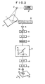
- a stimulable phosphor sheet 1 carrying a radiation image stored therein is scanned with a laser beam emitted from a laser beam source 3 via a scanning mirror 2 to cause the phosphor sheet 1 to emit light in proportion to the radiation energy stored therein.
- the emitted light is received by a photomultiplier 4 to read out the radiation image stored in the phosphor sheet 1.
- the output of the photomultiplier 4 is amplified by an amplifier 5, logarithmically converted by a logarithmic conversion circuit 6, and then converted to a digital signal by an A/D conversion circuit 7.
- the digital signal thus obtained is once stored in a memory 8 such as a magnetic disk.
- a desired gradation correction curve is created according to the object and the purpose by rotating and/or parallel-shifting a reference gradation correction curve, which has been selected from several reference curves memorized in advance in an electronic computer, on the signal level-optical density coordinate system.
- the digital signal stored in the memory 8 is processed. This processing is conducted in a digital operation circuit.
- the digital signal obtained by the A/D conversion circuit 7 may be directly sent to the gradation correction circuit 9 for conducting the gradation correction.
- the output signal obtained by the processing in the digital operation circuit is then converted to an analog signal by a D/A conversion circuit 10.
- the analog signal is then converted to a light signal by an E/O modulator (light modulator), thereby to emit light of an amount corresponding to the light signal from a light source 12 for image reproducing.
- the light emitted from the light source 12 is condensed onto a recording material 14 such as a photographic film by a condenser lens 13. While the light impinges upon the recording material 14, the recording material 14 is two-dimensionally moved in the directions of the arrows. In this manner, a visible image is reproduced on the recording material 14.
- the stimulable phosphor sheet 1 is scanned with the laser beam while the phosphor sheet 1 is moved perpendicularly to the scanning direction.
- the recording material 14 is two-dimensionally moved while it is exposed to the light the optical axis of which is stationary.
- a desired gradation correction curve is obtained by rotating and/or parallel-shifting a reference gradation correction curve,- which is selected from about ten reference gradation correction curves, according to the object and the purpose. Therefore, many (for example, several hundreds of) desired gradation correction curves can be created easily by use of a smaller amount of information than the amount of information required in the conventional method. Accordingly, it is possible to reduce the size of the electronic computer used for the correction of gradation. Further, in this embodiment, since many gradation correction patterns are coordinated to a few reference patterns and the information is automatically arranged, it becomes easy to select a necessary gradation correction pattern and to quickly conduct the image processing.
- Figures 3 and 4 show the distribution of the amount of a radiation passing through the frontal chest of the human body.
- a curve 15 indicates the aforesaid distribution obtained when the radiation tube voltage is set to 100kVp.
- a curve 17 indicates the aforesaid distribution obtained when the radiation tube voltage is adjusted to 80kVp to record the radiation image of the same object as in Figure 3
- a curve 16 indicates the distribution obtained when the radiation tube voltage is adjusted to 120kVp to record the radiation image of the same object as in Figure 3.
- the x coordinate axis indicates the intensity of light emission
- the y coordinate axis indicates the frequency.
- the width of the distribution obtained when the radiation tube voltage is adjusted to 80kVp is larger than when it is adjusted to 100kVp, and the width of the distribution obtained when it is adjusted to 120kVp is smaller than when it is adjusted to l00kVp.
- Such a difference in the width of the distribution is generated since the output contrast is changed by a change in the radiation tube voltage.
- gradation correction curves adapted to the distributions at the tube voltages of 80kVp and 120kVp are obtained by rotating the gradation correction curve for the tube voltage of 100kVp, and gradation processing is conducted based on the gradation correction curves thus obtained.
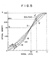
- Figure 5 shows the aforesaid three gradation correction curves 18, 19 and 20.
- the x coordinate axis indicates the electric signal level
- the y coordinate axis indicates the optical density of the reproduced visible image.
- the movement amount is calculated by multiplying the distance along the y coordinate axis between the point 21 and an arbitrary point Q on the curve 18 by the rotation coefficient (a), and the calculated movement amount is added to the y coordinate value of the center of rotation (i.e. the point 21), thereby to determine the y coordinate value of a point Q' on the curve obtained after the rotation, which corresponds to the point Q.
- the coordinates of the point Q' on the gradation correction curve 19 for the tube voltage of 80kVp which corresponds to the point Q and the coordinates of the point Q" on the gradation correction curve 20 for the tube voltage of l20kVp which corresponds to the point Q are represented by the following formulae:
- the output contrast is corrected by rotating the reference gradation correction curve and creating a desired gradation correction curve. Also when the object is changed or when the output contrast should partially be changed, an image of an appropriate image quality can be obtained in the same manner as described above.
Landscapes
- Engineering & Computer Science (AREA)
- Multimedia (AREA)
- Signal Processing (AREA)
- Physics & Mathematics (AREA)
- General Physics & Mathematics (AREA)
- Health & Medical Sciences (AREA)
- Life Sciences & Earth Sciences (AREA)
- High Energy & Nuclear Physics (AREA)
- Molecular Biology (AREA)
- Spectroscopy & Molecular Physics (AREA)
- Image Processing (AREA)
- Facsimile Image Signal Circuits (AREA)
- Image Analysis (AREA)
- Analysing Materials By The Use Of Radiation (AREA)
- Radiography Using Non-Light Waves (AREA)
- Control Of Exposure In Printing And Copying (AREA)
- Apparatus For Radiation Diagnosis (AREA)
Applications Claiming Priority (2)
| Application Number | Priority Date | Filing Date | Title |
|---|---|---|---|
| JP193770/82 | 1982-11-04 | ||
| JP57193770A JPS5983149A (ja) | 1982-11-04 | 1982-11-04 | 階調補正曲線の作成方法 |
Publications (2)
| Publication Number | Publication Date |
|---|---|
| EP0110185A1 true EP0110185A1 (de) | 1984-06-13 |
| EP0110185B1 EP0110185B1 (de) | 1987-02-04 |
Family
ID=16313512
Family Applications (1)
| Application Number | Title | Priority Date | Filing Date |
|---|---|---|---|
| EP83110988A Expired EP0110185B1 (de) | 1982-11-04 | 1983-11-03 | Verfahren und Vorrichtung zur Erzeugung einer Gradationskorrekturfunktion |
Country Status (4)
| Country | Link |
|---|---|
| US (1) | US4641267A (de) |
| EP (1) | EP0110185B1 (de) |
| JP (1) | JPS5983149A (de) |
| DE (2) | DE3369733D1 (de) |
Cited By (8)
| Publication number | Priority date | Publication date | Assignee | Title |
|---|---|---|---|---|
| GB2207023A (en) * | 1987-06-11 | 1989-01-18 | Seikosha Kk | Video printer |
| EP0376595A3 (de) * | 1988-12-28 | 1991-09-04 | Hewlett-Packard Company | Verfahren und Dokumentenabtaster zur Kontrast/Intensitäts-Steuerung |
| EP0488082A3 (en) * | 1990-11-24 | 1992-10-21 | Dainippon Screen Mfg. Co., Ltd. | Image processing method and apparatus |
| EP0538901A3 (en) * | 1991-10-25 | 1993-09-15 | Eastman Kodak Company | An adaptive technique for providing accurate tone reproduction control in an imaging system |
| EP0579186A1 (de) * | 1992-07-13 | 1994-01-19 | Mita Industrial Co., Ltd. | Bilderzeugungsgerät |
| FR2695282A1 (fr) * | 1992-09-01 | 1994-03-04 | Gen Electric Cgr | Procédé de réglage de contraste. |
| EP0691627A1 (de) * | 1994-07-04 | 1996-01-10 | Fuji Photo Film Co., Ltd. | Verfahren und Vorrichtung zur Gradationsumsetzung |
| EP0816929A3 (de) * | 1996-06-28 | 1998-09-30 | Kabushiki Kaisha Toshiba | Bilderzeugungsgerät |
Families Citing this family (20)
| Publication number | Priority date | Publication date | Assignee | Title |
|---|---|---|---|---|
| JPS6171035A (ja) * | 1984-09-13 | 1986-04-11 | 富士写真フイルム株式会社 | 放射線画像情報再生処理条件指示装置 |
| US4796086A (en) * | 1984-11-30 | 1989-01-03 | Fuji Photo Film Co., Ltd. | Method for converting color picture signals |
| JPH065919B2 (ja) * | 1985-02-15 | 1994-01-19 | コニカ株式会社 | 放射線画像の階調処理方法 |
| JPS6217875A (ja) * | 1985-07-15 | 1987-01-26 | Konishiroku Photo Ind Co Ltd | X線画像の画像処理装置 |
| US4807045A (en) * | 1986-07-18 | 1989-02-21 | Dainippon Screen Mfg. Co., Ltd. | Image data processing method and apparatus therefor |
| JPS6376077A (ja) * | 1986-09-19 | 1988-04-06 | Fujitsu Ltd | 画像処理装置における画像濃度変換方式 |
| US4786968A (en) * | 1987-07-16 | 1988-11-22 | Sony Corporation | Gamma correction of digital video data by calculating linearly interpolated gamma correction values |
| US5046118A (en) * | 1990-02-06 | 1991-09-03 | Eastman Kodak Company | Tone-scale generation method and apparatus for digital x-ray images |
| EP0557099B1 (de) * | 1992-02-21 | 1999-07-07 | Canon Kabushiki Kaisha | Gerät und Verfahren zur Bildverarbeitung |
| JPH06175452A (ja) * | 1992-12-11 | 1994-06-24 | Matsushita Electric Ind Co Ltd | 電子写真装置 |
| IL106691A (en) * | 1993-08-13 | 1998-02-08 | Sophis View Tech Ltd | System and method for diagnosis of living tissue diseases |
| EP0811205B1 (de) * | 1994-11-25 | 2003-09-10 | Sophisview Technologies, Ltd | System und verfahren zur diagnose von krankheiten an lebendem gewebe |
| US5761333A (en) * | 1995-01-31 | 1998-06-02 | General Electric Company | Contrast enhancement for CT systems |
| US5633511A (en) * | 1995-12-22 | 1997-05-27 | Eastman Kodak Company | Automatic tone scale adjustment using image activity measures |
| JP3075247B2 (ja) * | 1998-01-09 | 2000-08-14 | 日本電気株式会社 | カラー電子写真印刷装置 |
| US6370265B1 (en) | 1999-11-24 | 2002-04-09 | Direct Radiography Corp. | Method for generating gray scale transfer functions for use in displaying a digital radiogram |
| DE10213284B4 (de) * | 2002-03-25 | 2007-11-08 | Siemens Ag | Verfahren zur Bilddarstellung in der medizinischen Bildgebung |
| JP4323770B2 (ja) * | 2002-10-18 | 2009-09-02 | キヤノン株式会社 | 画像処理装置、画像処理方法、プログラム及び記録媒体 |
| US8559750B2 (en) * | 2010-11-08 | 2013-10-15 | Lg Innotek Co., Ltd. | Method of performing adaptive contrast enhancement using hyperbolic tangent curve and image histogram |
| JP6125656B2 (ja) * | 2012-11-29 | 2017-05-10 | コントローラッド システムズ、インコーポレイテッドControlrad Systems,Inc. | X線低減システム |
Citations (4)
| Publication number | Priority date | Publication date | Assignee | Title |
|---|---|---|---|---|
| US4149076A (en) * | 1976-04-05 | 1979-04-10 | Albert Richard D | Method and apparatus producing plural images of different contrast range by X-ray scanning |
| US4276473A (en) * | 1979-02-28 | 1981-06-30 | Fuji Photo Film Co., Ltd. | Gradation processing method and apparatus for radiation image recording system |
| GB2070885A (en) * | 1980-02-27 | 1981-09-09 | Dainippon Screen Mfg | Method and apparatus for setting up data for a photo-electric scanner |
| US4310886A (en) * | 1978-12-26 | 1982-01-12 | Fuji Photo Film, Co. Ltd. | Image gradation processing method and apparatus for radiation image recording system |
Family Cites Families (9)
| Publication number | Priority date | Publication date | Assignee | Title |
|---|---|---|---|---|
| DE2816462A1 (de) * | 1978-04-15 | 1979-10-25 | Philips Patentverwaltung | Verfahren zur erzeugung verbesserter rekonstruktionsbilder in computer-tomographiegeraeten |
| US4315318A (en) * | 1978-12-26 | 1982-02-09 | Fuji Photo Film Co., Ltd. | Method and apparatus for processing a radiation image |
| FR2461279B1 (fr) * | 1979-07-11 | 1987-01-02 | Fuji Photo Film Co Ltd | Procede de traitement d'une image radiographique |
| JPS5691735A (en) * | 1979-12-25 | 1981-07-24 | Fuji Photo Film Co Ltd | Method and apparatus for treating xxray image |
| JPS56104645A (en) * | 1979-12-25 | 1981-08-20 | Fuji Photo Film Co Ltd | Radiation picture treating method and its device |
| US4405920A (en) * | 1980-12-31 | 1983-09-20 | Naomi Weisstein | Enhancing the perceptibility of barely perceptible images |
| JPS57168579A (en) * | 1981-04-08 | 1982-10-16 | Fuji Photo Film Co Ltd | Method and device for reading of picture information |
| JPS5814270A (ja) * | 1981-07-17 | 1983-01-27 | Fuji Photo Film Co Ltd | 画像走査記録方法 |
| US4450478A (en) * | 1981-09-09 | 1984-05-22 | Georgetown University | Digital fluorographic method and system |
-
1982
- 1982-11-04 JP JP57193770A patent/JPS5983149A/ja active Granted
-
1983
- 1983-11-01 US US06/547,620 patent/US4641267A/en not_active Expired - Lifetime
- 1983-11-03 DE DE8383110988T patent/DE3369733D1/de not_active Expired
- 1983-11-03 DE DE198383110988T patent/DE110185T1/de active Pending
- 1983-11-03 EP EP83110988A patent/EP0110185B1/de not_active Expired
Patent Citations (4)
| Publication number | Priority date | Publication date | Assignee | Title |
|---|---|---|---|---|
| US4149076A (en) * | 1976-04-05 | 1979-04-10 | Albert Richard D | Method and apparatus producing plural images of different contrast range by X-ray scanning |
| US4310886A (en) * | 1978-12-26 | 1982-01-12 | Fuji Photo Film, Co. Ltd. | Image gradation processing method and apparatus for radiation image recording system |
| US4276473A (en) * | 1979-02-28 | 1981-06-30 | Fuji Photo Film Co., Ltd. | Gradation processing method and apparatus for radiation image recording system |
| GB2070885A (en) * | 1980-02-27 | 1981-09-09 | Dainippon Screen Mfg | Method and apparatus for setting up data for a photo-electric scanner |
Cited By (13)
| Publication number | Priority date | Publication date | Assignee | Title |
|---|---|---|---|---|
| GB2207023A (en) * | 1987-06-11 | 1989-01-18 | Seikosha Kk | Video printer |
| GB2207023B (en) * | 1987-06-11 | 1991-07-17 | Seikosha Kk | Video printer |
| EP0376595A3 (de) * | 1988-12-28 | 1991-09-04 | Hewlett-Packard Company | Verfahren und Dokumentenabtaster zur Kontrast/Intensitäts-Steuerung |
| EP0488082A3 (en) * | 1990-11-24 | 1992-10-21 | Dainippon Screen Mfg. Co., Ltd. | Image processing method and apparatus |
| EP0538901A3 (en) * | 1991-10-25 | 1993-09-15 | Eastman Kodak Company | An adaptive technique for providing accurate tone reproduction control in an imaging system |
| EP0579186A1 (de) * | 1992-07-13 | 1994-01-19 | Mita Industrial Co., Ltd. | Bilderzeugungsgerät |
| FR2695282A1 (fr) * | 1992-09-01 | 1994-03-04 | Gen Electric Cgr | Procédé de réglage de contraste. |
| US5426582A (en) * | 1992-09-01 | 1995-06-20 | Ge Medical Systems S.A. | Display and gradation correction curve setting method for operation thereof |
| EP0691627A1 (de) * | 1994-07-04 | 1996-01-10 | Fuji Photo Film Co., Ltd. | Verfahren und Vorrichtung zur Gradationsumsetzung |
| US5796865A (en) * | 1994-07-04 | 1998-08-18 | Fuji Photo Film Co., Ltd. | Gradation correcting method and apparatus |
| EP0816929A3 (de) * | 1996-06-28 | 1998-09-30 | Kabushiki Kaisha Toshiba | Bilderzeugungsgerät |
| US6078401A (en) * | 1996-06-28 | 2000-06-20 | Kabushiki Kaisha Toshiba | Image forming apparatus |
| US6188489B1 (en) | 1996-06-28 | 2001-02-13 | Kabushiki Kaisha Toshiba | Image forming apparatus |
Also Published As
| Publication number | Publication date |
|---|---|
| JPH0526138B2 (de) | 1993-04-15 |
| DE3369733D1 (en) | 1987-03-12 |
| US4641267A (en) | 1987-02-03 |
| DE110185T1 (de) | 1984-10-11 |
| JPS5983149A (ja) | 1984-05-14 |
| EP0110185B1 (de) | 1987-02-04 |
Similar Documents
| Publication | Publication Date | Title |
|---|---|---|
| US4641267A (en) | Gradation correction curve creating method and apparatus | |
| EP0112469B2 (de) | Anwendung eines Energiedifferenzverfahrens zur Erzeugung von Strahlungsbildern unter Verwendung von Phosphorschichten sowie Phosphorschichten zusammen mit Filtern | |
| US4496973A (en) | Radiation image read-out method and apparatus | |
| US4302672A (en) | Image gradation processing method and apparatus for radiation image recording system | |
| US4310886A (en) | Image gradation processing method and apparatus for radiation image recording system | |
| US4527060A (en) | Radiation image read-out method and apparatus | |
| US4276473A (en) | Gradation processing method and apparatus for radiation image recording system | |
| US4590517A (en) | Subtraction processing method for radiation images | |
| US4320296A (en) | Method of and apparatus for recording image processing data in radiation image recording system | |
| US4498006A (en) | Radiation image read-out method and apparatus | |
| US4564861A (en) | Subtraction processing method and apparatus for radiation images | |
| US4527061A (en) | Radiation image read-out method and apparatus | |
| US4584482A (en) | Noise erasing method and apparatus for stimulable phosphor sheet | |
| US4439866A (en) | Arbitrary layer tomographic method and apparatus | |
| US4581535A (en) | Method of recording X-ray image | |
| EP0089665A1 (de) | System und Anordnung zum Subtrahieren von Röntgenbildern | |
| US4683377A (en) | Subtraction processing method and apparatus for radiation images | |
| EP0094678B1 (de) | Rauschunterdrückung in einem Verfahren zum Aufzeichnen und Wiedergeben eines Strahlungsbildes | |
| EP0145982B1 (de) | Skalenfaktoreinstellverfahren für Strahlungsbilder | |
| US4568832A (en) | Radiation image read-out method and apparatus | |
| US5665976A (en) | Radiation image read-out and erasing method and apparatus | |
| EP0152563B1 (de) | Verfahren und Vorrichtung zur Aufzeichnung und zum Auslesen eines Strahlungsbildes | |
| US4485481A (en) | Computed tomographic method | |
| EP0151717B1 (de) | Verfahren und Vorrichtung zur Aufzeichnung und zum Auslesen eines Strahlungsbildes | |
| EP0166922A1 (de) | Verfahren und Vorrichtung zum Auslesen eines Strahlungsbildes |
Legal Events
| Date | Code | Title | Description |
|---|---|---|---|
| PUAI | Public reference made under article 153(3) epc to a published international application that has entered the european phase |
Free format text: ORIGINAL CODE: 0009012 |
|
| AK | Designated contracting states |
Designated state(s): DE FR NL |
|
| TCNL | Nl: translation of patent claims filed | ||
| 17P | Request for examination filed |
Effective date: 19840629 |
|
| EL | Fr: translation of claims filed | ||
| DET | De: translation of patent claims | ||
| GRAA | (expected) grant |
Free format text: ORIGINAL CODE: 0009210 |
|
| AK | Designated contracting states |
Kind code of ref document: B1 Designated state(s): DE FR NL |
|
| REF | Corresponds to: |
Ref document number: 3369733 Country of ref document: DE Date of ref document: 19870312 |
|
| ET | Fr: translation filed | ||
| PLBE | No opposition filed within time limit |
Free format text: ORIGINAL CODE: 0009261 |
|
| STAA | Information on the status of an ep patent application or granted ep patent |
Free format text: STATUS: NO OPPOSITION FILED WITHIN TIME LIMIT |
|
| 26N | No opposition filed | ||
| PGFP | Annual fee paid to national office [announced via postgrant information from national office to epo] |
Ref country code: FR Payment date: 20021119 Year of fee payment: 20 |
|
| PGFP | Annual fee paid to national office [announced via postgrant information from national office to epo] |
Ref country code: NL Payment date: 20021125 Year of fee payment: 20 |
|
| PGFP | Annual fee paid to national office [announced via postgrant information from national office to epo] |
Ref country code: DE Payment date: 20021227 Year of fee payment: 20 |
|
| PG25 | Lapsed in a contracting state [announced via postgrant information from national office to epo] |
Ref country code: NL Free format text: LAPSE BECAUSE OF EXPIRATION OF PROTECTION Effective date: 20031103 |
|
| NLV7 | Nl: ceased due to reaching the maximum lifetime of a patent |
Effective date: 20031103 |