EP0110398A2 - Elektrostatisches Kopiergerät - Google Patents
Elektrostatisches Kopiergerät Download PDFInfo
- Publication number
- EP0110398A2 EP0110398A2 EP83112018A EP83112018A EP0110398A2 EP 0110398 A2 EP0110398 A2 EP 0110398A2 EP 83112018 A EP83112018 A EP 83112018A EP 83112018 A EP83112018 A EP 83112018A EP 0110398 A2 EP0110398 A2 EP 0110398A2
- Authority
- EP
- European Patent Office
- Prior art keywords
- gear
- interlocking
- shaft
- rotating
- supporting frame
- Prior art date
- Legal status (The legal status is an assumption and is not a legal conclusion. Google has not performed a legal analysis and makes no representation as to the accuracy of the status listed.)
- Granted
Links
- 230000005540 biological transmission Effects 0.000 claims abstract description 29
- 239000000463 material Substances 0.000 claims description 122
- 230000007246 mechanism Effects 0.000 claims description 76
- 238000010438 heat treatment Methods 0.000 claims description 59
- 230000009471 action Effects 0.000 claims description 56
- 230000002093 peripheral effect Effects 0.000 claims description 52
- 238000004140 cleaning Methods 0.000 claims description 28
- 230000001788 irregular Effects 0.000 claims description 23
- 230000000994 depressogenic effect Effects 0.000 claims description 7
- 230000000452 restraining effect Effects 0.000 claims description 7
- 239000004033 plastic Substances 0.000 claims description 4
- 230000004044 response Effects 0.000 claims description 4
- 230000036961 partial effect Effects 0.000 description 14
- 238000010276 construction Methods 0.000 description 10
- 239000000470 constituent Substances 0.000 description 9
- 230000002411 adverse Effects 0.000 description 8
- 210000000078 claw Anatomy 0.000 description 8
- 230000006835 compression Effects 0.000 description 8
- 238000007906 compression Methods 0.000 description 8
- 230000003287 optical effect Effects 0.000 description 8
- 238000000034 method Methods 0.000 description 6
- XEEYBQQBJWHFJM-UHFFFAOYSA-N Iron Chemical group [Fe] XEEYBQQBJWHFJM-UHFFFAOYSA-N 0.000 description 5
- 102100029469 WD repeat and HMG-box DNA-binding protein 1 Human genes 0.000 description 5
- 101710097421 WD repeat and HMG-box DNA-binding protein 1 Proteins 0.000 description 5
- 230000001276 controlling effect Effects 0.000 description 5
- 230000000875 corresponding effect Effects 0.000 description 5
- 230000002079 cooperative effect Effects 0.000 description 3
- 239000013256 coordination polymer Substances 0.000 description 3
- 229920003051 synthetic elastomer Polymers 0.000 description 3
- 239000005061 synthetic rubber Substances 0.000 description 3
- 238000011144 upstream manufacturing Methods 0.000 description 3
- 230000006399 behavior Effects 0.000 description 2
- 239000011248 coating agent Substances 0.000 description 2
- 238000000576 coating method Methods 0.000 description 2
- 230000007547 defect Effects 0.000 description 2
- 238000010586 diagram Methods 0.000 description 2
- 230000000694 effects Effects 0.000 description 2
- 239000002783 friction material Substances 0.000 description 2
- 230000008439 repair process Effects 0.000 description 2
- 239000007779 soft material Substances 0.000 description 2
- 229920006362 Teflon® Polymers 0.000 description 1
- 239000000956 alloy Substances 0.000 description 1
- 229910045601 alloy Inorganic materials 0.000 description 1
- 238000005452 bending Methods 0.000 description 1
- 230000008901 benefit Effects 0.000 description 1
- 230000003139 buffering effect Effects 0.000 description 1
- 230000003247 decreasing effect Effects 0.000 description 1
- 238000007599 discharging Methods 0.000 description 1
- 238000006073 displacement reaction Methods 0.000 description 1
- 230000005484 gravity Effects 0.000 description 1
- 238000003780 insertion Methods 0.000 description 1
- 230000037431 insertion Effects 0.000 description 1
- 239000002184 metal Substances 0.000 description 1
- 229910052751 metal Inorganic materials 0.000 description 1
- 238000012986 modification Methods 0.000 description 1
- 230000004048 modification Effects 0.000 description 1
- 239000004745 nonwoven fabric Substances 0.000 description 1
- 230000008569 process Effects 0.000 description 1
- 230000001105 regulatory effect Effects 0.000 description 1
- 230000002441 reversible effect Effects 0.000 description 1
- 230000000630 rising effect Effects 0.000 description 1
- 238000007665 sagging Methods 0.000 description 1
- 239000007787 solid Substances 0.000 description 1
- 230000003068 static effect Effects 0.000 description 1
Images


Classifications
-
- G—PHYSICS
- G03—PHOTOGRAPHY; CINEMATOGRAPHY; ANALOGOUS TECHNIQUES USING WAVES OTHER THAN OPTICAL WAVES; ELECTROGRAPHY; HOLOGRAPHY
- G03G—ELECTROGRAPHY; ELECTROPHOTOGRAPHY; MAGNETOGRAPHY
- G03G21/00—Arrangements not provided for by groups G03G13/00 - G03G19/00, e.g. cleaning, elimination of residual charge
- G03G21/16—Mechanical means for facilitating the maintenance of the apparatus, e.g. modular arrangements
- G03G21/18—Mechanical means for facilitating the maintenance of the apparatus, e.g. modular arrangements using a processing cartridge, whereby the process cartridge comprises at least two image processing means in a single unit
- G03G21/1839—Means for handling the process cartridge in the apparatus body
- G03G21/1857—Means for handling the process cartridge in the apparatus body for transmitting mechanical drive power to the process cartridge, drive mechanisms, gears, couplings, braking mechanisms
-
- G—PHYSICS
- G03—PHOTOGRAPHY; CINEMATOGRAPHY; ANALOGOUS TECHNIQUES USING WAVES OTHER THAN OPTICAL WAVES; ELECTROGRAPHY; HOLOGRAPHY
- G03G—ELECTROGRAPHY; ELECTROPHOTOGRAPHY; MAGNETOGRAPHY
- G03G15/00—Apparatus for electrographic processes using a charge pattern
- G03G15/20—Apparatus for electrographic processes using a charge pattern for fixing, e.g. by using heat
- G03G15/2003—Apparatus for electrographic processes using a charge pattern for fixing, e.g. by using heat using heat
- G03G15/2014—Apparatus for electrographic processes using a charge pattern for fixing, e.g. by using heat using heat using contact heat
- G03G15/2017—Structural details of the fixing unit in general, e.g. cooling means, heat shielding means
- G03G15/2032—Retractable heating or pressure unit
-
- G—PHYSICS
- G03—PHOTOGRAPHY; CINEMATOGRAPHY; ANALOGOUS TECHNIQUES USING WAVES OTHER THAN OPTICAL WAVES; ELECTROGRAPHY; HOLOGRAPHY
- G03G—ELECTROGRAPHY; ELECTROPHOTOGRAPHY; MAGNETOGRAPHY
- G03G15/00—Apparatus for electrographic processes using a charge pattern
- G03G15/20—Apparatus for electrographic processes using a charge pattern for fixing, e.g. by using heat
- G03G15/2003—Apparatus for electrographic processes using a charge pattern for fixing, e.g. by using heat using heat
- G03G15/2014—Apparatus for electrographic processes using a charge pattern for fixing, e.g. by using heat using heat using contact heat
- G03G15/2039—Apparatus for electrographic processes using a charge pattern for fixing, e.g. by using heat using heat using contact heat with means for controlling the fixing temperature
-
- G—PHYSICS
- G03—PHOTOGRAPHY; CINEMATOGRAPHY; ANALOGOUS TECHNIQUES USING WAVES OTHER THAN OPTICAL WAVES; ELECTROGRAPHY; HOLOGRAPHY
- G03G—ELECTROGRAPHY; ELECTROPHOTOGRAPHY; MAGNETOGRAPHY
- G03G15/00—Apparatus for electrographic processes using a charge pattern
- G03G15/65—Apparatus which relate to the handling of copy material
- G03G15/6502—Supplying of sheet copy material; Cassettes therefor
-
- G—PHYSICS
- G03—PHOTOGRAPHY; CINEMATOGRAPHY; ANALOGOUS TECHNIQUES USING WAVES OTHER THAN OPTICAL WAVES; ELECTROGRAPHY; HOLOGRAPHY
- G03G—ELECTROGRAPHY; ELECTROPHOTOGRAPHY; MAGNETOGRAPHY
- G03G15/00—Apparatus for electrographic processes using a charge pattern
- G03G15/65—Apparatus which relate to the handling of copy material
- G03G15/6529—Transporting
-
- G—PHYSICS
- G03—PHOTOGRAPHY; CINEMATOGRAPHY; ANALOGOUS TECHNIQUES USING WAVES OTHER THAN OPTICAL WAVES; ELECTROGRAPHY; HOLOGRAPHY
- G03G—ELECTROGRAPHY; ELECTROPHOTOGRAPHY; MAGNETOGRAPHY
- G03G15/00—Apparatus for electrographic processes using a charge pattern
- G03G15/75—Details relating to xerographic drum, band or plate, e.g. replacing, testing
- G03G15/757—Drive mechanisms for photosensitive medium, e.g. gears
-
- G—PHYSICS
- G03—PHOTOGRAPHY; CINEMATOGRAPHY; ANALOGOUS TECHNIQUES USING WAVES OTHER THAN OPTICAL WAVES; ELECTROGRAPHY; HOLOGRAPHY
- G03G—ELECTROGRAPHY; ELECTROPHOTOGRAPHY; MAGNETOGRAPHY
- G03G21/00—Arrangements not provided for by groups G03G13/00 - G03G19/00, e.g. cleaning, elimination of residual charge
- G03G21/16—Mechanical means for facilitating the maintenance of the apparatus, e.g. modular arrangements
- G03G21/1604—Arrangement or disposition of the entire apparatus
- G03G21/1623—Means to access the interior of the apparatus
- G03G21/1628—Clamshell type
-
- G—PHYSICS
- G03—PHOTOGRAPHY; CINEMATOGRAPHY; ANALOGOUS TECHNIQUES USING WAVES OTHER THAN OPTICAL WAVES; ELECTROGRAPHY; HOLOGRAPHY
- G03G—ELECTROGRAPHY; ELECTROPHOTOGRAPHY; MAGNETOGRAPHY
- G03G21/00—Arrangements not provided for by groups G03G13/00 - G03G19/00, e.g. cleaning, elimination of residual charge
- G03G21/16—Mechanical means for facilitating the maintenance of the apparatus, e.g. modular arrangements
- G03G21/1642—Mechanical means for facilitating the maintenance of the apparatus, e.g. modular arrangements for connecting the different parts of the apparatus
- G03G21/1647—Mechanical connection means
-
- G—PHYSICS
- G03—PHOTOGRAPHY; CINEMATOGRAPHY; ANALOGOUS TECHNIQUES USING WAVES OTHER THAN OPTICAL WAVES; ELECTROGRAPHY; HOLOGRAPHY
- G03G—ELECTROGRAPHY; ELECTROPHOTOGRAPHY; MAGNETOGRAPHY
- G03G2215/00—Apparatus for electrophotographic processes
- G03G2215/20—Details of the fixing device or porcess
-
- G—PHYSICS
- G03—PHOTOGRAPHY; CINEMATOGRAPHY; ANALOGOUS TECHNIQUES USING WAVES OTHER THAN OPTICAL WAVES; ELECTROGRAPHY; HOLOGRAPHY
- G03G—ELECTROGRAPHY; ELECTROPHOTOGRAPHY; MAGNETOGRAPHY
- G03G2221/00—Processes not provided for by group G03G2215/00, e.g. cleaning or residual charge elimination
- G03G2221/16—Mechanical means for facilitating the maintenance of the apparatus, e.g. modular arrangements and complete machine concepts
- G03G2221/1651—Mechanical means for facilitating the maintenance of the apparatus, e.g. modular arrangements and complete machine concepts for connecting the different parts
- G03G2221/1654—Locks and means for positioning or alignment
-
- G—PHYSICS
- G03—PHOTOGRAPHY; CINEMATOGRAPHY; ANALOGOUS TECHNIQUES USING WAVES OTHER THAN OPTICAL WAVES; ELECTROGRAPHY; HOLOGRAPHY
- G03G—ELECTROGRAPHY; ELECTROPHOTOGRAPHY; MAGNETOGRAPHY
- G03G2221/00—Processes not provided for by group G03G2215/00, e.g. cleaning or residual charge elimination
- G03G2221/16—Mechanical means for facilitating the maintenance of the apparatus, e.g. modular arrangements and complete machine concepts
- G03G2221/1651—Mechanical means for facilitating the maintenance of the apparatus, e.g. modular arrangements and complete machine concepts for connecting the different parts
- G03G2221/1657—Mechanical means for facilitating the maintenance of the apparatus, e.g. modular arrangements and complete machine concepts for connecting the different parts transmitting mechanical drive power
-
- G—PHYSICS
- G03—PHOTOGRAPHY; CINEMATOGRAPHY; ANALOGOUS TECHNIQUES USING WAVES OTHER THAN OPTICAL WAVES; ELECTROGRAPHY; HOLOGRAPHY
- G03G—ELECTROGRAPHY; ELECTROPHOTOGRAPHY; MAGNETOGRAPHY
- G03G2221/00—Processes not provided for by group G03G2215/00, e.g. cleaning or residual charge elimination
- G03G2221/16—Mechanical means for facilitating the maintenance of the apparatus, e.g. modular arrangements and complete machine concepts
- G03G2221/1672—Paper handling
- G03G2221/1675—Paper handling jam treatment
-
- G—PHYSICS
- G03—PHOTOGRAPHY; CINEMATOGRAPHY; ANALOGOUS TECHNIQUES USING WAVES OTHER THAN OPTICAL WAVES; ELECTROGRAPHY; HOLOGRAPHY
- G03G—ELECTROGRAPHY; ELECTROPHOTOGRAPHY; MAGNETOGRAPHY
- G03G2221/00—Processes not provided for by group G03G2215/00, e.g. cleaning or residual charge elimination
- G03G2221/16—Mechanical means for facilitating the maintenance of the apparatus, e.g. modular arrangements and complete machine concepts
- G03G2221/1678—Frame structures
- G03G2221/1687—Frame structures using opening shell type machines, e.g. pivoting assemblies
-
- G—PHYSICS
- G03—PHOTOGRAPHY; CINEMATOGRAPHY; ANALOGOUS TECHNIQUES USING WAVES OTHER THAN OPTICAL WAVES; ELECTROGRAPHY; HOLOGRAPHY
- G03G—ELECTROGRAPHY; ELECTROPHOTOGRAPHY; MAGNETOGRAPHY
- G03G2221/00—Processes not provided for by group G03G2215/00, e.g. cleaning or residual charge elimination
- G03G2221/16—Mechanical means for facilitating the maintenance of the apparatus, e.g. modular arrangements and complete machine concepts
- G03G2221/18—Cartridge systems
- G03G2221/183—Process cartridge
- G03G2221/1853—Process cartridge having a submodular arrangement
Definitions
- This invention relates to some improvements in an electrostatic copying apparatus, particularly a shell-type electrostatic copying apparatus.
- electrostatic copying apparatuses of the so-called shell-type which have a first and a second supporting frames connected to each other so that they can pivot relative to each other between an open position and a closed position (usually, a lower supporting frame disposed at a predetermined position and an upper supporting frame mounted on the lower supporting frame for pivotal movement between an open position and a closed position) have already been proposed and come into commercial acceptance.
- a shell-type electrostatic copying apparatus at least a considerable portion of a conveying passage for a sheet material such as a copying paper on which to form a copied image is opened by relatively pivoting the first and second supporting framesto bring them to the open position.
- this offers the advantage that in the event that jamming occurs in the conveying passage, the sheet material can be easily taken out from it.
- the conventional shell-type electrostatic copying apparatuses still have problems to be solved, among which are:
- electrostatic copying apparatuses not limited to those of the shell-type described above, include a fixing device for fixing a toner image on the surface of a sheet material such as a copying paper, a mechanism for conveying the sheet material as required, and a paper feeding device of the cassette type.
- a fixing device for fixing a toner image on the surface of a sheet material such as a copying paper
- a mechanism for conveying the sheet material as required and a paper feeding device of the cassette type.
- Conventional electrostatic copying apparatuses also have problems to be solved with regard to these devices. The following are typical of these problems.
- a second object of this invention is to provide an improved electrostatic copying apparatus of the aforesaid shell-type in which mounting and detaching of a rotating drum on an upper supporting frame mounted for free pivotal movement between an open position and a closed position on a lower supporting frame disposed at a predetermined position, and mounting and detaching of a cleaning device, a charging corona discharge device and a developing device located around the rotating drum are achieved fully easily and rapidly.
- a third object of this invention is to provide an improved fixing device in which a pair of fixing rollers are maintained in press contact with each other upon energization of a drive power source, and are at least partly moved away from each other upon deenergization of the drive power source.
- a fifth object of this invention is to provide an improved copying paper feed device in which at the time of loading and removing a copying paper cassette, the uppermost sheet of a layer of copying paper sheets in the cassette is prevented from being adversely affected by feed rollers.
- a sixth object of this invention is to provide an improved electrostatic copying apparatus in which excessive consumprtion of power by an electrical heating element in a fixing device is inhibited and fixing rollers are prevented from being adversely affected by a toner which remains adhering to the fixing rollers.
- an electrostatic copying apparatus having a first and a second supporting frames connected to each other for relative pivotal movement between an open position and a closed position, wherein
- an electrostatic copying apparatus including a lower supporting frame and an upper supporting frame mounted on the lower supporting frame for free pivotal movement about the central axis of pivoting extending in the front-rear direction between an open position and a closed position, the upper supporting frame having a rotating drum with a photosensitive material on its peripheral surface mounted thereon for free rotation about the central axis of rotation extending in the front-rear direction, and further including a cleaning device, a charging corona discharge device and a developing device mounted around the rotating drum in this order viewed in the rotating direction of the rotating drum; wherein the rotating drum and the developing device are mounted on a first unit frame and constitute a first unit, the cleaning device and the charging corona device are mounted on a second unit frame and constitute a second unit, and the first unit frame and the second unit frame are each mounted detachably on the upper supporting frame.
- a fixing device for fixing a toner image on the surface of a sheet material comprising a rotatably mounted driven fixing roller drivingly connected to a drive source and a rotatably mounted follower fixing roller;
- a sheet material conveying mechanism comprising a rotatably mounted driven shaft drivingly connected to a drive source, a plurality of conveying rollers mounted on the driven shaft in spaced-apart relationship in the longitudinal direction of the driven shaft, and a plurality of stationary guide members each located opposite to the driven shaft and between the adjacent conveying rollers, the distance between the lower edge of each guide member and the peripheral surface of the driven shaft being slightly shorter than the distance between the peripheral surface of the driven shaft and the peripheral surface of each conveying roller.
- a copying paper feed device in an electrostatic copying apparatus comprising a combination of a copying paper cassette and a copying paper cassette receiving section permitting loading of the cassette therein by inserting at least the front end portion of the cassette, the paper cassette including a box-like cassette case opened at least at the front end portion of its upper surface, a bottom plate disposed within the cassette case and on which to place a layer of copying paper sheets, and a spring means for elastically biasing the front end portion of the bottom plate upwardly, the cassette receiving section having provided therein a rotatably mounted rotating shaft drivingly connected to a drive source and a feed roller mounted on the rotating shaft, and said device being of the type in which when the copying paper cassette is loaded in position into the cassette receiving section, the front end portion of the uppermost copying paper in the sheet-like copying paper layer is brought into press contact with the feed roller by the elastic biasing action of the spring member;
- an electrostatic copying apparatus equipped with a heat fixing device having a pair of fixing rollers for cooperatively fixing a toner image to the surface of a sheet material, one of the fixing rollers being drivingly connected to a drive source and at least one of the fixing rollers including an electrical heating element;
- a sheet material conveying device generally shown at 38 is disposed in the lower section of the housing 2. At one end (the right end in Figure 1) of the sheet material conveying device 38, a cassette-type copying paper feed device 40 and a manual sheet feeding device 42 located above it are provided.
- the paper feed device 40 is comprised of a combination of a paper cassette receiving section 46 having a feed roller 44 provided therein and a copying paper cassette 50 to be loaded in the cassette receiving section 46 through an opening 48 formed in the right wall of the housing 2, and copying paper sheets are fed one by one from a layer 52 of copying paper cassette 50 by the action of the feed roller 44 (the paper feed device 40 will be described in greater detail hereinafter).
- the manual feeding device 42 includes a horizontal guide plate 56 projecting outwardly through an opening 54 formed in the right wall of the housing 2, a guide plate 58 located above the guide plate 56 and a pair of feed rollers 60 and 62 located downstream (left in Figure 1) of these guide plates 56 and 58.
- a suitable sheet material such as a copying paper sheet is positioned on the horizontal guide plate 56 and advanced to the nipping position of the pair of feed rollers 60 and 62, the feed rollers 60 and 62 nip the sheet material and feed it.
- the sheet material is conveyed by the action of a suitable conveyor belt mechanism 78 to a fixing device 80 (which will be described in greater detail hereinafter). Thereafter, it is discharged onto a receiving tray 84 through an opening 82 formed in the left wall of the housing 2.
- the optical unit 86 includes a document illuminating lamp 88 for illuminating the document on the transparent plate 4, and a first reflecting mirror 90, a second reflecting mirror 92, a third reflecting mirror 94, a lens assembly 96 and a fourth reflecting mirror 98 for projecting the light reflected from the document onto the photosensitive material.
- the document illuminating lamp 88 and the first reflecting mirror 90 are moved from a scanning exposure start position shown by a solid line substantially horizontally to a required position (for example, a maximum scanning exposure end position shown by a two-dot chain line) at a required velocity V
- the second reflecting mirror 92 and the third reflecting mirror 94 are moved from a scanning exposure start position shown by a solid line to a required position (for example, a maximum scanning exposure end position shown by a two-dot chain line) at a velocity half of the aforesaid required velocity V (i.e., at 1V).
- the light reflected from the document illuminated by the document illuminating lamp 88 is successively reflected by the first reflecting mirror 90, the second reflecting mirror 92 and the third reflecting mirror 94, and reaches the lens assembly 96.
- the light is reflected by the fourth reflecting mirror 98 and reaches the photosensitive material in the exposure zone 18 through an opening 100 formed in the horizontal plate 8.
- the document illuminating lamp 88, the first reflecting mirror 90, the second reflecting mirror 92 and the third reflecting mirror 94 are returned to the scanning exposure start position shown by the solid line.
- the charging corona discharge device 28 charges the photosensitive material to a specified polarity substantially uniformly in the charging zone 16. Then, in the exposure zone 18, the optical unit 86 projects an image of the document to form a latent electrostatic image corresponding to the document on the charged photosensitive material. In the developing zone 20, the developing device 30 applies a toner to the latent electrostatic image on the photosensitive material to develop the latent electrostatic image to a toner image.
- a sheet material such as a copying paper fed from the paper feed device 40 or the manual feeding device 42 is contacted with the photosensitive material, and by the action of the transfer corona discharge device 32, the toner image on the photosensitive material is transferred to the sheet material.
- the sheet material is peeled from the photosensitive material by the action of the peeling corona discharge device 34.
- the sheet material having the toner image transferred thereto is then conveyed to the fixing device 80 to fix the toner image, and then discharged into the receiving tray 84.
- the rotating drum continues to rotate, and in the cleaning zone 26, the toner and the static charge remaining on the photosensitive material after transfer are removed by the action of the cleaning device 36.
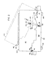
- the illustrated copying apparatus constructed in accordance with this invention is equipped with a so-called shell-type supporting structure constructed of a first supporting frame, or a lower supporting frame, 102 and a second supporting frame, or an upper supporting frame, 104 which are connected to each other for relative pivotal movement.
- a supporting protruding portion 112 projecting upwardly is formed, and a pivotal supporting shaft 114 extending in the front-rear direction is mounted on the supporting protruding portion 112 (also see Figure 3).
- the front end and the rear end of the supporting shaft 114 project somewhat forwardly and rearwardly of the supporting protruding portions 112 of the vertical front base plate 108 and the vertical rear base plate 110, respectively.
- the upper supporting frame 104 also includes a vertical front base plate 116 and a vertical rear base plate 118 which are disposed in spaced-apart relationship in the front-rear direction (a direction perpendicular to the sheet surface in Figure 2) ( Figure 2 shows only the vertical front base plate 116, and for the vertical rear base plate 118, see Figures 3 and 7).
- the distance in the front-rear direction between the vertical front base plate 116 and the vertical rear base plate 118 of the supporting frame 104 is slightly larger than the distance in the front-rear direction between the vertical front base plate 108 and the vertical rear base plate 110 of the lower supporting frame 102.
- the vertical front base plate 116 and the vertical rear base plate 118 of the upper supporting frame 104 are located slightly forwardly and rearwardly of the vertical front base plate 108 and the vertical rear base plate 110 of the lower supporting frame 102, respectively.
- a downwardly projecting protruding support portion 120 is formed in the right end portion of each of the vertical front base plate 116 and the vertical rear base plate 118 of the upper supporting frame 104, and a nearly semicircular cut 122 is formed at the lower edge of protruding support portion 120.
- the cuts 122 formed in the lower edges of the protruding support portions 120 are engaged with the opposite end portions of the supporting shaft 114 (i.e., its front end portion and rear end portion projecting beyond the vertical front base plate 108 and the vertical rear base plate 110 of the lower supporting frame 102 forwardly and rearwardly, respectively), and as a result, the supporting frame 104 is mounted on the lower supporting frame 102 for free pivotal movement about the support shaft 114.
- a restraining member (not shown) having a hole through which the supporting shaft 114 passes is fixed to each of the protruding support portion 120 of the supporting frame 104 thereby to prevent surely the upward movement of the protruding support portions 120.
- the linking piece 128 of one compression coil spring 126 is privotally connected to a pin 132 set firmly in the front surface of the vertical front base plate 108 of the lower supporting frame 102, and the linking piece 130 is connected pivotally to a pin 134 set firmly in the vertical front base plate 116 of the upper supporting frame 104.
- the linking piece 128 of the other compression coil spring 126 is connected pivotally to a pin 132 set firmly in the rear surface of the vertical rear base plate 110 of the lower supporting frame 102, and the linking piece 130 is connected pivotally to a pin 134 firmly set in the rear surface of the vertical rear base plate 118 of the upper supporting frame 104 ( Figure 7).
- the lower supporting frame 102 and the upper supporting frame 104 also have provided therein a locking mechanism for locking the upper supporting frame 104 at the closed position shown in Figure 2 against the elastic biasing action of the spring means 124.
- An engaging pin 136 is set firmly in the upper portion of the left end of the front surface of the vertical front base plate 108 of the lower supporting frame 102, and a supporting pin 138 is set firmly in the lower portion of the left end of the front surface of the vertical front base plate 116 of the upper supporting frame 104.
- a hook 140 to be engaged with the engaging pin 136 is mounted on the supporting pin 138.
- the hook 140 is mounted on the supporting pin 138 so that it can freely pivot clockwise in Figure 2 from the angular position shown in the drawing, and is elastically biased counterclockwise in Figure 2 and elastically held at the angular position shown in the drawing by spring means (not shown).
- the lower end of the hook 140 is inclined upwardly to the right in the drawing.
- an operating piece 142 protruding outwardly beyond the left edge of the upper supporting frame 104 is provided in the hook 140.
- an engaging pin 136 and a hook 140 are likewise provided in the top left end of the rear surface of the vertical rear base plate 110 of the lower supporting frame 102 and the left end bottom of the rear surface of the vertical rear base plate 118 of the supporting frame 104 (see Figure 7).
- the operating piece 142 of the hook 140 provided on the front surface may be linked with the operating piece 142 of the hook 140 provided on the rear surface by a suitable member extending in the front-rear direction (i.e., a direction perpendicular to the sheet surface in Figure 2) to interlock the two hooks 140.
- the supporting frame 104 is surely locked at the closed position shown by the solid line in Figure 2 against the elastic biasing action of the spring means 124.
- the operating piece 142 of the hook 140 is manually operated to pivot the hook 140 clockwise about the supporting pin 138 as a center and to disengage it from the engaging pin 136, the upper supporting frame 104 is pivoted about the supporting shaft 114 as a center, to the open position shown by the two-dot chain line in Figure 2 by the elastic biasing action of the spring means 124.
- any sheet material which has jammed up in this portion can be easily taken out (it will be easily understood from Figure 1 that by only bringing the upper supporting frame 104 to the open position shown by the two-dot chain line in Figure 2, the sheet material conveying passage in the fixing device 80 is not opened, and to completely open the sheet material conveying passage, an additional operation is required; this will be described in detail hereinafter).
- a front cover and a rear cover are also mounted on the lower supporting frame 102 and the upper supporting frame 104 (if further required, a right end cover for covering the right end surface thereof and a left end cover for covering the left end surface thereof may also be mounted).
- These covers are suitably divided into a lower section and an upper section.
- the lower sections are mounted on the lower supporting frame 102, and the upper sections are mounted on the upper supporting frame 104 and pivoted between the closed position and the open position together with the upper supporting frame 104.
- the second unit shown generally at 146 has a second unit frame 148, and the cleaning device 36 including a cleaning blade 150 and a charge eliminating lamp 152 and the charging corona discharge device 28 are mounted on the second unit frame 148.
- the second unit frame 148 has a front wall 154 and a rear wall 156 spaced from each other in the front-rear direction, and side members 158 and 160 are fixed to, and between, the front wall 154 and the rear wall 156.
- a blade supporting mechanism 162 is mounted on the side member 158.
- a blade holding member 164 is provided at one end portion of the blade supporting mechanism 162.
- the blade supporting mechanism 162 itself includes an electromagnetic solenoid (not shown) for controlling a half-rotating spring clutch means (not shown) and a suitable spring means (not shown).
- an electromagnetic solenoid for controlling a half-rotating spring clutch means (not shown) and a suitable spring means (not shown).
- the electromagnetic solenoid is energized (or deenergized)
- the cleaning blade 150 is held at an operating position shown by a solid line in Figure 4 (at which position the free end of the cleaning blade 150 is pressed against the photosensitive material on the rotating drum 12) by the elastic biasing action of the spring means.
- the cleaning blade 150 When the electromagnetic solinoid is deenergized (or energized), the cleaning blade 150 is held at a non-operating position shown by a two-dot chain line in Figure 4 (at which the free end of the cleaning blade 150 is moved away from the photosensitive material on the rotating drum 12).
- the construction of the blade supporting mechanism 162 itself does not constitute a novel characteristic in the illustrated copying apparatus improved in accordance with this invention, and may be substantially the same as the construction disclosed in the specification and drawings of Japanese Patent Application No. 191276/1981 filed November 27, 1981 (entitled "CLEANING DEVICE OF ELECTROSTATIC COPYING APPARATUS"). Accordingly, a description of the construction of the blade supporting mechanism 162 itself is omitted in the present specification.
- a supporting member 166 is fixed to the lower surface of the left end portion of the side member 158, and the base portion of a shielding material 168 formed of a flexible material is fixed to the supporting member 166.
- the free end of the shielding member 168 projecting from the base portion fixed to the supporting member 166 contacts the photosensitive material on the rotating drum 12 relatively weakly to prevent the toner removed from the photosensitive material by the action of the cleaning blade 150 from being dissipated in the direction shown by an arrow 170.
- Downwardly directed openings 176 are formed respectively in the front wall 154 and the rear wall 156 of the second unit frame 148 immediately downstream of the charge eliminating lamp 152 viewed in the rotating direction 14 of the rotating drum l2.
- a supporting rail 178 extends across the front wall 154 and the rear wall 156 and is fixed to the upper end edge portions of these openings 176.
- guide rails 182 and 184 are fixed to the opposite end portions of the upper wall of a shield case 180 for the charging corona discharge device 28.
- the charging corona discharge device 28 are mounted detachably at a required position by engaging the guide rails 182 and 184 with the supporting rail 178 and moving them in the direction perpendicular to the sheet surface in Figure 4.
- charge eliminating lamps 190 (only one is shown in Figure 4) having a light emitting source 186 and a case 188 are fixed respectively to the front end portion and the rear end portion of the under surface of the upper surface portion of the side member 160.
- the light emitting source 186 of the charge eliminating lamp 190 is selectively energized when the width of a sheet material conveyed to the transfer zone 22 is smaller than the width of the photosensitive material on the rotating drum 12 and therefore it is desired to form a latent electrostatic image only on a part of the photosensitive member in the widthwise direction.
- the light emitting source 186 illuminates both side portions of the photosensitive material through an opening 192 formed in the case 188 and selectively removes a charge from both sides of the photosensitive material which is charged substantially uniformly by the charging corona discharge device 28 over substantially the entire width of the photosensitive material.
- engaging hooks 202 are pivotally mounted by supporting pins 200 set firmly in the rear surface of the front wall 154 and the front surface of the rear wall 156 respectively.
- the front engaging hook 202 and the rear engaging hook 202 are connected to each other by a nearly L-shaped linking member 204 extending therebetween.
- Projecting pieces 206 projecting forwardly and rearwardly are formed respectively on the upper portions of the front engaging hook 202 and the rear engaging hook 202.
- a spring member 208 constructed of a torsion coil spring.
- One end of the spring means 208 abuts against the upper surface of the left end portion of the side member 158 fixed to, and between, the front wall 154 and the rear wall 156 of the second unit frame 148, and its other end abuts against the projecting piece 206.
- the spring member 208 elastically biases the engaging hooks 202 counterclockwise in Figure 4.
- the engaging hooks 202 are held at their operating position shown in Figures 3 to 5
- the projecting pieces 206 of the engaging hooks 202 abut against the upwardly extending protruding portions,210 formed in the other end portions (the left edge portions in Figure 4) of the front wall 154 and the rear wall 156 of the second unit frame 148.
- each engaging hook 202 is prevented from pivoting further clockwise in Figure 4. It will be clear therefore that the engaging hooks 202 are elastically held at the operating position shown in Figures 3 to 5 by the spring means 208.
- the upper end edge 203 of each engaging hook 202 is inclined downwardly to the left in Figure 4.
- the second unit 146 in mounting the second unit 146 on the upper supporting frame 104, the second unit 146 is inserted between the vertical front base plate 116 and the vertical rear base plate 118 of the upper supporting frame 104 from below the upper supporting frame 104 positioned at the open position shown by the two-dot chain line in Figure 3, and the slots 198 formed in the front wall 154 and the rear wall 156 of the second unit 146 both at one edge portion are engaged with the supporting rod 194. Then, the second unit 146 is pivoted clockwise about the supporting rod 194 as a center as viewed from ahead of the unit 146 thereby to raise the other edge portion of the second unit 146.
- each of the engaging hooks 202 abuts against, and interferes with, the supporting rod 196, whereby the engaging hooks 202 are pivoted clockwise as viewed from ahead of the engaging hooks 202 against the elastic biasing action of the spring means 208.
- the inclined upper end edge 203 of each engaging hook 202 goes past the supporting rod 196.
- the engaging hooks 202 are returned to the operating position shown in Figures 3 to 5 by the elastic biasing action of the spring means 208 and engaged with the supporting rod 196.
- the second unit 146 is mounted at a required position by the supporting rods 194 and 196.
- the illustrated developing device 30 is constructed of a developing mechanism 222 and a toner supply mechanism 224.
- the developing mechanism 222 has a developer container 226 for accommodating a developer composed of a carrier and a toner, an agitating means 232 including an agitating plate 228 and a plurality of agitating blades 230 disposed on both surfaces of the agitating plate 228, and a magnetic brush means 238 comprised of a cylindrical sleeve 234 and a roll-like stationary permanent magnet 236 disposed within the cylindrical sleeve 234.
- the agitating means 232 is rotated counterclockwise in Figure 1 to agitate the developer in the developer container 226 and to charge the toner triboelectorically.
- the sleeve 234 of the magnetic brush means 238 is rotated clockwise in Figure 1.
- the sleeve 234 holds the developer onto its surface by the magnetic attracting force of the permanent magnet 236 disposed therein, applies the developer to the photosensitive material on the rotating drum.12 and thus selectively causes the toner to adhere to the photosensitive material according to a latent electrostatic image formed on the photosensitive material.
- the toner supply mechanism 224 is comprised of a toner container 240 for holding a toner therein, a hollow cylindrical toner cartridge 242 to be mounted above one end portion of the toner container 240, a toner conveying means 244 disposed in the toner container 240, and a toner supply means 246.
- the toner cartridge 242 has an openable discharge outlet 248 to be formed at a predetermined angular position of its perpheral side wall. After opening the discharge outlet 248, the cartridge 242 is inserted into the toner container 240 through a circular opening formed in the front surface of the toner container 240 while its discharge outlet 248 is positioned upwardly.
- the cartridge 242 is turned to assume the state shown in Figure 1 in which the discharge outlet 248 is located downwardly.
- the toner accommodated in the toner cartridge 242 is discharged downwardly through the discharge outlet 248 and supplied to the toner container 240.
- the toner conveying means 244 of a suitable form located below the discharge outlet 248 of the toner cartridge 242 is driven by a motor (not shown) exclusively used for toner supplying and mounted on the rear surface of the toner container 240, and conveys the toner discharged from the discharge opening 248 of the toner cartridge 242 to the left in Figure 1.
- the toner supply means 246 of a suitable form disposed in the right end lower portion of the toner container 240 is driven by the aforesaid motor exclusively used for toner supplying (not shown), and supplies the toner conveyed by the toner conveying means 244 to the developer container 226 of the developing mechanism 222 through an opening 250 formed in the left end of the toner container 240.
- To the left end wall of the toner container 240 is fixed a cover 252 extending therefrom to the left and covering the upper portion of the developing mechanism 222.
- the developing device 30 itself composed of the developing mechanism 222 and the toner supply mechanism 224 does not constitute a novel characteristic of the copying apparatus constructed in accordance with this invention, and is merely one example of a developing device that can be used. A further detailed description of the developing device 30 will, therefore, be omitted in this specification.
- the developer container 226 of the developing mechanism 222 is fixed to, and between, the front wall 216 and the rear wall 218 of the first unit frame 220 by screwing a setscrew 258 in a screw hole 256 formed in the left edge portion of the developer container 226 through holes 254 formed in the front wall 216 and the rear wall 218 of the first unit frame 220 and screwing a setscrew 264 in a screw hole 262 formed in the right end portion of the developer container 226 through holes 260 formed in the front wall 216 and the rear wall 218 of the first unit frame 220.
- the agitating means 232 of the developing mechanism 222 has shaft supporting members 266 having a circular peripheral surface and mounted on its front end portion and rear end portion, and is mounted rotatably between the front wall 216 and the rear wall 218 of the first unit frame 220 by mounting the shaft supporting members 266 in holes 268 formed in the front wall 216 and the rear wall 218 of the first unit frame 220.
- the magnetic brush means 238 has shaft supporting members 270 having a circular peripheral surface and mounted on its front end portion and rear end portion, and is rotatably mounted between the front wall 216 and the rear wall 218 of the first unit frame 220 by fitting the shaft supporting member 270 in holes 272 formed in the front wall 216 and the rear wall 218 of the first unit frame 220.
- gears 274 and 276 are fixed respectively to the rear end of the agitating means 232 and the rear end of the magnetic brush means 238.
- these gears 274 and 276 are brought into engagement with each other.
- a drive source such as an electric motor constituting a main drive source for the copying apparatus through a suitable power transmission system.
- the toner supply mechanism 224 as an integral unit is fixed to the developer container 226 by screwing a setscrew 282 in a screw hole 280 formed in a protruding portion present in the right edge portion of the developer container 226 through holes 278 formed in protruding portions present in the front surface and rear surface of the toner container 240.
- restraining pieces 290 ( Figure 6 shows only a lower restraining piece by a two-dot chain line) conveniently having semi-circular cuts 288 at the lower ends thereof are fixed to the rear surface of the vertical front base plate 116 and the front surface of the vertical rear base plate 118 in the upper supporting frame 104 on which the first unit 214 is to be mounted.
- the cuts 288 of the restraining pieces 290 abut, immediately inwardly of the receiving sections 284, against the upper half surfaces of the shaft supporting members 286 mounted on the opposite ends of the rotating drum 12.
- the shaft supporting members 286 are surely prevented from moving upwardly from the receiving sections 284.
- the restraining pieces 290 may also be detachably mounted on the first unit frame 220.
- a gear 292 is fixed to the rear end portion of the rotating drum 12.
- the gear 292 is drivingly connected through a suitable power transmission system to a drive source such as an electric motor constituting a main drive source for the copying apparatus when the first unit,214 is mounted on the upper supporting frame 104 in the required manner.
- slots 294 extending upwardly from the lower edge thereof and then extending to the right are formed respectively in the vertical front base plate 116 and the vertical rear base plate l18 of the upper supporting frame 104. Furthermore, at positions spaced a predetermined distance to the left from the slots 294, a forwardly extending projecting piece 296 and a rearwardly extending projecting piece 296 are formed in the vertical front base plate 116 and the vertical rear base plate 118 of the upper supporting frame 104.
- an engaging rod 298 is mounted on the right edge portion of the front wall 216 and the right edge portion of the rear wall 218 in the first unit frame 220.
- the engaging rod 298 is mounted in the required manner on the first unit frame 220 by inserting its opposite end portions into holes 300 formed respectively in the right edge portion of the front wall 216 and the right edge portion of the rear wall 218 of the first unit frame 220.
- the opposite end portions of the engaging rod 298 mounted on the first unit frame 220 project forwardly and rearwardly beyond the front wall 216 and the rear wall 218, respectively.
- protrusions 302 extending forwardly and rear-wardly are formed respectively in the left edge portion of the front wall 216 and the left edge portion of the rear wall 218 of the first unit frame 220.
- the opposite end portions of the engaging rod 298 at one edge portion of the first unit 214 i.e., its opposite end portions projecting forwardly and rearwardly beyond the front wall 216 and the rear wall 218, are engaged with the slots 294 formed in the vertical front base plate 116 and the vertical rear base plate 118 of the upper supporting frame 104.
- the first unit 214 is pivoted clockwise as seen from ahead of it about the engaging rod 298 in the slots 294 as a center, thereby to raise the other end edge portion of the first unit 214.
- the protrusions 302 formed in the other edge portion of the front wall 216 and the other edge portion of the rear wall 218 in the first unit frame 220 are positioned immediately below the protruding pieces 296 formed in the vertical front base plate l16 and the vertical rear base plate 118 of the upper supporting frame 104. Thereafter, a setscrew 304 projecting upwardly through each protrusion 302 is manipulated and screwed in a screw hole 306 formed in each protruding piece 296.
- the first unit 214 is mounted in the required manner between the vertical front base plate 116 and the vertical rear base plate 118 of the upper supporting frame 1,04.
- the first unit 214 can be detached from the upper supporting frame 104 by manipulating the setscrew 304 to remove it from the screw hole 306 in the protruding piece 296, thus releasing the screwing of the protruding piece 296 and the protrusion 302, and then detaching the engaging rod 298 from the slots 294.
- the second unit 146 is located above the first unit 214. Accordingly, when the first unit 214 and the second unit 146 are to be mounted on the upper supporting frame 104, it is necessary first to mount the second unit 146 and then the first unit 214. To detach them from the upper supporting frame 104, it is necessary to detach the first unit 214 first and then detach the second unit 146.
- the second power transmission system 312 provided on the upper supporting frame 104 will first be described.
- an output shaft 314 of the drive source 308 projects rearwardly through the vertical rear base plate 118 of the upper supporting frame 104, and a sprocket wheel 316 is fixed to the projecting end portion of the output shaft 314.
- the second power transmission system 312 further includes sprocket wheels 318, 320, 322, 324 and 326.
- An endless chain 328 is wrapped about the sprocket wheels 316, 318, 320, 322, 324 and 326.
- the sprocket wheels 316, 318, 320, 322, 324 and 326 are rotated in the directions shown by arrows.
- the sprocket wheel 318 is connected through a clutch mechanism (not shown) for scanning movement to a known optical unit driving mechanism (not shown) for driving the document illuminating lamps 88, the first reflecting mirror 90, the second reflecting mirror 92 and the third reflecting mirror 94 of the optical unit 86.
- the sprocket wheel 320 is connected to the optical unit driving mechanism (not shown) through a clutch mechanism (not shown) for return movement.
- the document illuminating lamp 88, the first reflecting mirror 90, the second reflecting mirror 92 and the third reflecting mirror 94 of the optical unit 86 are moved for scanning to the right in Figure 1.
- the clutch mechanism for return movement is actuated, the document illuminating lamp 88, the first reflecting mirror 90, the second reflecting mirror 92 and the third reflecting mirror 94 of the optical unit 86 are caused to make a returning movement to the left in Figure 1.
- a gear 330 is connected to the sprocket wheel 322 so that it can rotate as a unit with the sprocket wheel 3,22.
- the gear 330 is in mesh with a gear 276 (see Figure 6 also) fixed to the magnetic brush means 238 of the developing device 30 and a gear 292 (see Figure 6 also) fixed to the rotating drum 12.
- the sprocket wheel 324 is connected to a half-rotating spring clutch means (not shown) utilized to hold the cleaning blade 150 ( Figure 4) at its operating position or a non-operating position. (For details about the half-rotating spring clutch means, see the specification and drawings of the above-cited Japanese Patent Application No. 191276/ 1981).
- the sprocket wheel 326 is an idle sprocket wheel for maintaining the endless chain 328 taut.
- the interlocking linking gear 334 comes into engagement with the interlocking input gear 336.
- the interlocking input gear 336 is drivingly connected to the drive source 308 through the interlocking output gear 332 and the interlocking linking gear 334 (the interlocking output gear 332, the interlocking linking gear 334 and the interlocking input gear 336 will be described in more detail hereinafter).
- the first power transmission system 310 provided in the lower supporting frame 102 includes a gear 338 which is rotatably mounted on the vertical rear base plate 110 of the lower supporting frame lQ2 and is in mesh with the interlocking input gear 336.
- a gear 341 is in mesh with the gear 338.
- the gear 314 is connected to the driven belt wheel (the belt wheel in the left of Figure 1) of the conveying blet mechanism 78 ( Figure 1) so that it rotates as a unit with the belt wheel.
- a sprocket wheel 340 is connected to the gear 338 so that it can rotate as a unit with the gear 338.
- the first power transmission system 310 further includes sprocket wheels 342, 344, 346 and 348, and an endless chain 350 is wrapped about the sprocket wheels 340, 342, 344, 346 and 348.
- the sprocket wheels 342 and 348 are idle sprocket wheels for maintaining the endless chain 350 taut.
- the sprocket wheel 344 is connected to the conveying rollers70 and 72 ( Figure 1) so that it can rotate as a unit with the roller 70.
- the sprocket wheel 346 is connected to the feed roller 44 ( Figure 1) of the copying paper feed device 40 through a clutch means (this clutch means will be described in more detail hereinafter).
- the sprocket wheel 346 is also connected to a gear 352 so that it can rotate as a unit with the gear 352.
- a gear 354 is in mesh with the gear 352.
- the gear 354 is connected to the feed roller 62 so that it can rotate as a unit with the roller 62.
- the first power transmission system 310 further includes a gear train composed of gears 356, 358, 360 and 362. These gears 356, 358, 360 and 362 will be described in detail hereinafter with regard to the fixing device 80.
- the interlocking linking gear 334 In order for the interlocking linking gear 334 to come smoothly into and out of engagement with.the interlocking input gear 336 by its movement in a circular arcuate track irrespective of the rotating angular positions which the interlocking linking gear 334 and the interlocking input gear 336 assume upon stopping of their rotation by the deenergization of the drive source 308, it is important that one of the gears 334 and 336 should be properly rotated over some angular range at the time of their engagement and disengagement.
- the illustrated copying apparatus constructed in accordance with this invention is improved in the following respect with regard to its interlocking mechanism comprised of the interlocking output gear 332, the interlocking linking gear 334 and the interlocking input gear 336.
- This fixing is achieved by threadably fitting a setscrew 364, which abuts against, or is threadedly associated with, the output shaft 314, in a radial hole formed in the hub portion of the sprocket wheel 316.
- the sprocket wheel 316 has a small-diameter hub portion 366 at its right end portion in Figure 8, and the interlocking output gear 332 is mounted on the small-diameter hub portion 366.
- one or more (two in the drawing) fan-shaped raised portions 368 are formed on the peripheral surface of the small-diameter hub portion 366 of the sprocket wheel 316.
- one or more (two in the drawing) fan-shaped depressed portions 370 are formed on the inner circumferential surface of the interlocking output gear 332.
- the interlocking output gear 332 is mounted on the small-diameter hub portion 366.
- the angle of circumferential extension of each fan-shaped depressed portion 370 (angle a which is 90 degrees in the drawing) is slightly (by 6 degrees in the drawing) larger than the angle of the circumferential extension of the each fan-shaped raised portion 368 (angle ⁇ which is 84 degrees in the drawing).
- the interlocking output gear 332 is mounted on the small-diameter hub portion 366 of the sprocket wheel 316 in such a manner that it can freely rotate over some angular range (a - 8) corresponding to the difference (a - ⁇ ) between the angle a and the angle P with respect to the small-diameter hub portion 366 and the output shaft 314 to which the small-diameter hub portion 366 is fixed. Since the difference (a - S) between the angle a and the angle ⁇ , i.e.
- the above angular difference is desirably a value corresponding to one-half pitch of the interlocking output gear 332 (and the interlocking linking gear 334 in mesh therewith) or a slightly larger value.
- the interlocking output gear 332 is mounted on the small-diameter hub portion 366 of the sprocket wheel 316 fixed to the output shaft 314.'If desired, however, the interlocking output gear 332 can be directly mounted on the output shaft 314. Furthermore, in the illustrated embodiment, the fan-shaped raised portions 368 are formed on the peripheral surface of the small-diameter hub portion 366, and the fan-shaped depressed portions 370, on the inner circumferential surface of the interlocking output gear 332. Conversely, it is possible to form the fan-shaped depressed portions on the peripheral surface of the small diameter hub portion 366 and the fan-shaped raised portions on the inner circumferential surface of the interlocking output gear 332.
- annular member 372 having a small-diameter portion and a large-diameter portion is rotatably mounted on the output shaft 314 of the drive source 308.
- the movement of the annular member 372 in the right direction in Figure 8 is prevented by a stop plate 373 fixed to the output shaft 314.
- annular member 376 having a small-diameter portion and a large-diameter portion is rotatably mounted on a medium-diameter hub portion 374 of the sprocket wheel 316 adjacent to the small-diameter hub portion 366.
- a pivot member 378 is fixed to the small-diameter portions of the annular members 372 and 376, and consequently, is pivotally mounted on the output shaft 314.
- the pivot member 378 has a main portion 380, a supporting piece 382 projecting laterally from the upper edge of one end portion of the main portion 380 and then extending downwardly, and a guide piece 384 projecting laterally from the other end portion of the main portion 380 in a direction opposite to the supporting piece 382 and then extending downwardly.
- a protruding portion 386 is formed at one end of the guide piece 384.
- the lower end portion of the guide piece 384 is slightly curved in a direction away from the main portion 380, i.e. to the left in Figure 8.
- Corresponding circular openings 388 and 390 are formed in the main portion 380 and the supporting piece 382 of the pivot member 378.
- a shaft 400 projecting rearwardly (to the left in Figure 8) beyond the vertical rear base plate 110 is fixed to the lower supporting frame 102.
- the shaft 400 is rotatably mounted the interlocking input gear 336 by means of a shaft supporting member 402.
- the shaft 400 has an extension projecting rearwardly a predetermined distance beyond the interlocking input gear 336.
- the extension of the shaft 400 constitutes a stop member against which the free edge, i.e. lower edge, of the main portion 380 of the pivot member 378 abuts when the upper supporting frame 104 is held at its closed position and the interlocking linking gear 334 is brought into engagement with the interlocking input gear 336.
- the front end of the shaft 400 guides the front surface (the right surface in Figure 8) of the guide piece 384 of the pivot member 378 when the upper supporting frame 104 is brought to its closed position. Censequently, the free edge, i.e. lower edge, of the main portion 380 of the pivot member 378 is surely prevented from being displaced toward the base portion of the shaft 400 (to the right in Figure 8) and damaging the interlocking input gear 336 upon collision.
- the pivot member 378 can be pivoted slightly counterclockwise about the output shaft 314 as a center against the elastic biasing action of the spring means 398, and thus the abutting of the teeth of the interlocking linking gear 334 against the teeth of the interlocking input gear 336 is elastically buffered.
- the interlocking output gear 332 is mounted on the output shaft 314 so that it can freely rotate over some range, the interlocking linking gear 334 and the interlocking output gear 332 in mesh therewith are slightly rotated, as required, substantially simultaneously with the aforesaid elastic buffering, and thus the interlocking linking gear 334 is fully smoothly engaged with the interlocking input gear 336.
- the rotation of the interlocking linking gear 334 and the interlocking output gear 332 is also effected when the pivot member 378 is slightly pivoted countercloclwise about the output shaft 314 as a center against the elastic biasing action of the spring member 398 and thereby the linking gear 334 is slightly turned around the output gear 332. Accordingly, even when the teeth of the linking gear 334 abut against the teeth of the input gear 336 in alignment with each other, the linking gear 334 can be fully smoothly engaged with the input gear 336.
- pivot member 378 in the lower supporting frame 102 in relation to the interlocking input gear 336 and to mount the interlocking linking gear 334 on the pivot member 378 so provided. In this case, it is necessary to maintain the interlocking input gear 336 instead of the interlocking output gear 332 freely rotatable over some angular range with respect to the first power transmission system 310 provided in the lower supporting frame 102.
- the construction of the copying paper feed device 40 will be described in detail with reference to Figures 1 and 12-A together.
- the illustrated paper feed device 40 is composed of a combination of the paper cassette receiving section 46, and the paper cassette 50 loaded in the cassette receiving section 46 through the opening 48 formed in the right wall of the housing 2, as already mentioned hereinabove.
- a spring means 410 composed of a compression coil spring is interposed between the front end portion of the bottom plate 408 and the bottom wall of the cassette case 404.
- the spring means 410 elastically biases the front end portion of the bottom plate 408 upwardly.
- the copying paper sheet layer 52 is accommodated in the cassette case 404 while at least its front portion is placed on the bottom plate 408. Hence, the front end portion of the copying paper sheet layer 52 is also elastically biased upwardly by the spring means 410.
- Within the cassette case 404 are disposed a pair of separating claw members 412 (only one of the separating claw portions 412 is shown in Figures 1 and 12-A).
- Each separating claw member 412 has a supporting portion 414 located between the side wall of the cassette case 404 and the guide plate 406 and a separating claw portion 416 extending inwardly from the upper edge of the front end of the supporting portion 414 and adapted to be kept in stoppage on the front end corner portion of the upper surface of the copying paper sheet layer 52.
- the upper end portion of the rear portion of the supporting portion 414 is pivotally connected to the guide plate 406 (or the side wall of the cassette case 404) by a pin 418, and the separating claw members 412 are free to pivot about the pin 418 as a center.
- the clockwise pivoting of the separating claw members 412 in Figure 12-A is restricted by the abutting of the rear end edge of the supporting portion 414 against the bottom wall of the cassette case 404.
- the rotating input element 436 has formed integrally therewith the sprocket wheel 346 and the gear 352 which are constituent elements of the first power transmission system 310 described hereinabove.
- the sprocket wheel 346 is drivingly connected to the drive source 308 ( Figure 1), and the gear 352 is in mesh with the gear 354 connected to the feed roller 62 ( Figure 1) of the manual feed device 42 so that it rotates as a unit with the roller 62.
- a spring clutch means of a unique construction shown generally at 438 (which will be described in greater detail hereinafter) is disposed between the rotating shaft 428 and the rotating input element 436.
- Two supporting sleeves 440 spaced from each other a predetermined distance are fixed to the main portion of the rotating shaft 428, i.e. that portion which exists between the verical front base plate 108 and the vertical rear base plate 110 of the lower supporting frame 102.
- Auxiliary sleeves 442 are also fixed outwardly of the upporting sleeves 440 with some distance.
- the feed rollers 44 preferably formed of a material having a relatively high coefficient of friction such as a synthetic rubber are fixed to the peripheral surfaces of the two supporting sleeves 440, respectively.
- the irregular arcuate member 430 is rotatably mounted on the rotating shaft 428.
- the bottom plate 408 and the front end portion of the copying paper sheet layer 52 placed on it are lowered by the action of the irregular arcuate members 430 against the elastic biasing action of the spring means 410.
- the uppermost copying paper sheet in the copying paper sheet layer 52 is substantially prevented from contacting the peripheral surface of the feed roller 44 and thereby being adversely affected.
- the irregular arcuate members 430 performing the above-mentioned operation are rotatably mounted on the rotating shaft 428 to which the feed roller 44 is fixed, in the embodiment described above. If desired, however, it is possible to provide another shaft extending substantially parallel, and in proximity, to the rotating shaft 428 and mount them on this shaft.
- a spring clutch means which does not permit free rotation of the rotating shaft 428 but hampers its rotation when it is not operating (i.e. when the rotation of the rotation input element 436 is not transmitted to the rotatint shaft 428) is used as a clutch means for choosing between the rotating input element 436 and the rotating shaft 428.
- the free rotation of the rotating shaft 428 is not permitted, the following problem exists.
- the action of the irregular arcuate members 430 makes it possible to substantially prevent the uppermost copying paper in the sheet-like copying paper layer 52 from contacting the peripheral surface of the feed roller 44 and being adversely affected.
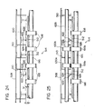
- the spring clutch means 438 includes a tubular rotating element 454 idly fitted in the hub portion 450 formed in the rotation input element 436 and the small-diameter portion of a tubular member 452 fixed to the rotating shaft 428, and a coil spring 456 disposed inwardly of the rotating element 454.
- One end of the coil spring 456 is fixed to the hub portion 450 of the rotating input element 436, and its other end is fixed to the rotating element 454.
- the wrapping direction of the coil spring 456 wrapped about the hub portion 450 of the rotating input element 436 and the small-diameter portion of the tubular member 452 is anticlockwise when viewed from ritht in Figure 13.
- the spring clutch means 438 further comprises a friction member 460 mounted pivotally on a supporting pin 458 projecting to the right in Figure 13 and fixed firmly in the vertical rear base plate 110 of the lower supporting frame 102 and a control means for selectively holding the friction member 460 at a non-operating position shown by a solid line in Figure 14 and an operating position shown by a two-dot chain line in Figure 14.
- the main portion of the control means is constructed of a solenoid 462 fixed to the vertical rear base plate 110.
- the solenoid 462 has an iron core 466 having an enlarged head portion 464 and a compression coil spring 468 received about the axial portion of the iron core 466.
- One end of the friction member 460 is bifurcated to receive the axial portion of the iron core 466 of the solenoid 462.
- the solenoid 462 is deenergized and the iron core 466 is at its projecting position shown by a solid line in Figure 14 by the elastic biasing action of the spring 468, the friction member 460 is held at its non-operating position shown.by the solid line in Figure 14.
- the solenoid 462 is energized and the iron core 466 is held at its retracted position shown by a two-dot chain line in Figure 14 against the elastic biasing action of the spring 468, the friction member 460 is held at its operating position shown by the two-dot chain line in Figure 14.
- the coil spring 456 having one end fixed to the rotating input element 436 and the other end to the rotating element 454 does not shrink since it is not restrained whatsoever by the rotating element 454 and freely rotate incident to the rotation of the rotating input element 436.
- the tubular member 452 and the rotating shaft 428 fixed to it are permitted to rotate freely in both directions without any restraining.
- the solenoid 426 is energized and the friction member 460 is held at its operating position shown by the two-dot chain line in Figure 14, the free end of the friction member 460 is pressed against the peripheral surface of the rotating element 454 and thereby a frictional resistance is exerted on the rotation of the rotating element 454.
- the coil spring 456 wrapped from one end fixed to the rotation input element 436 to the other end fixed to the rotating element 454 anticlockwise as viewed from right in Figure 13 is shrunken and wrapped tightly about the hub portion 450 of the rotation input element 436 and the small-diameter portion of the tubular member 452 fixed to the rotating shaft 428 because its one end is forcibly rotated counterclockwise as viewed from right in Figure 13 by the rotating input element 436 whereas the other end undergoes a resistance force by the frictional resistance exerted on the rotating element 454.
- the rotating input element 436, the tubular member 452 and the rotating shaft 428 to which the tubular member 452 is fixed are connected by the coil spring 456, and therefore, the rotating shaft 428 is rotated counterclockwise, i.e. in the feeding direction, as viewed from right in Figure 13 incident to the rotation of the rotation input element 436.
- the shrunken coil spring 456 and the rotating element 454 to which the aforesaid other end of the coil spring 456 is fixed are rotated counterclockwise as viewed from right in Figure 13 against the frictional resistance and incident to the rotation of the rotating input element 436 while it continues to undergo a frictional resistance by the friction member 460 pressed against the peripheral surface of the rotating element 454 (and therefore, while the coil spring 456 continues to be maintained shrunken).
- the rotating shaft 428 and the feed rollers 44 fixed thereto are allowed to rotate.freely during the non-operating period of the spring clutch means 438, namely during the deenergization of the solenoid 462. Accordingly, even when the uppermost copying paper sheet in the copying paper sheet layer 52 in the cassette case 404 contines to be in contact with the feed roller 44 at the time of removing the cassette 50 from the cassette receiving section 46, the feed roller 44 is properly rotated in a direction opposite to the feeding direction in response to the movement of the uppermost copying paper, and therefore, the aforesaid problem does not arise.
- the rotating shaft 428 and the feed roller 44 fixed thereto are allowed to rotate freely during the non-operating period of the spring clutch means 438, namely during the deenergization of the solenoid 462.
- the uppermost copying paper sheet in the copying paper sheet layer in the cassette case 404 is prevented from being adversely affected by the feed roller 44 upon contact therewith.
- the aforesaid irregular arcuate members 430 may be omitted.
- the irregular arcuate members 430 are omitted, the following undesirable tendency arises.
- the leading edge of the uppermost copying paper sheet in the copying paper sheet layer 52 accommodated in the cassette case 404 abuts directly against the peripheral surface of the feed roller 44 not tangent, but nearly normal thereto.
- the feed roller 44 is generally formed of a material having a relatively high coefficient of friction in order to perform surely its inherent function of feeding copying paper.
- a stationary guide plate 470 of the form illustrated in Figure 15 may be used instead of the irregular arcuate member 430. It is important that the stationary guide plate 470 conveniently fixed in a required position with regard to each of the feed rollers 44 fixed to the rotating shaft 428 should have a guiding lower edge 472 extending inclinedly downwardly in the inserting direction (in the left direction in Figure 15) of the cassette 50 ( Figure 12-A, for example). The guiding lower edge 472 extends inclinedly downwardly in the inserting direction of the cassette 50 and further extends substantially horizontally.
- the front end portion of the guiding lower edge 472 should be located slightly above the lower end of the peripheral surface of the feed roller 44 (if the front end portion of the guiding lower edge 472 projects downwardly beyond the lower end of the peripheral surface of the feed roller 44, the upper most copying paper in the sheet-like copying paper layer 52 in the loaded cassette 50 is prevented from contacting the peripheral surface of the feed roller 44, and therefore, the action of the feed rollers 44 to feed the copying paper is hampered).
- At least the guiding lower edge 472 of the stationary guide plate 470 is desirably formed of a suitable plastic material or the like having a low coefficient of friction.
- the uppermost copying paper sheet in the sheet-like copying paper layer 52 abuts against the guiding lower edge 472 of the stationary guide plate 470 at the time of inserting the cassette 50 into the cassette-receiving section 46 and advances along the guiding lower edge 472 (at this time, the bottom plate 408 and the front end portion of the copying paper sheet layer 52 placed thereon are gradually lowered against the elastic biasing action of the spring means 410 by the action of the guiding lower edge 472). Then, the uppermost copying paper sheet leaves the guiding lower edge 472 at its front end portion and comes into contact with the peripheral surface of the feed rollers 44.
- the illustrated fixing device 80 includes a driven fixing roller 474 and a follower fixing roller 476.
- the driven fixing roller 474 is composed of a hollow cylindrical member 478 rotatably mounted and adapted to rotate in the direction shown by an arrow and an electrical heating element 480 disposed within the hollow cylindrical member 478.
- the hollow cylindrical member 478 can be made of a suitable metal such as an aluminum-base alloy having a suitable surface coating, such as a Teflon (trademark) coating, which effectively prevents adhesion of a toner.
- the electrical heating element 480 may be a resistance heater extending longitudinally of, and within, the hollow cylindrical member 478.
- the follower fixing roller 476 rotatably supported and adapted to be in press contact with the driving fixing roller 474 is conveniently formed of a suitable flexible material such as a synthetic rubber.
- the fixing device 80 is entirely mounted on the lower supporting frame 102. Hence, even when the upper supporting frame 104 is held at its open position, the conveying passage for a sheet material such as copying paper which passes through the fixing device 80 is not opened (see Figures 1 and 2 also). Thus, the illustrated embodiment is constructed such that after the upper supporting frame 104 is held at its open position, the conveying passage for a sheet material passing through the fixing device 80 can also be opened as required. This construction will be described in detail.
- the illustrated fixing device 80 has a movable supporting frame 484 mounted on the shaft 400 so that it can pivot freely between a closed position shown by a solid line in Figure 16 and an open position shown by a two-dot chain line in Figure 16.
- the shaft 400 itself is fixed to the vertical front base plate 108 and the vertical rear base plate 110 ( Figure 3) of the lower supporting frame 102. As already described with reference to Figure 8, the rear end portion of the shaft 400 projects rearwardly beyond the vertical rear base plate 110, and the interlocking input gear 336 is rotatably mounted on the shaft 400.
- the movable supporting frame 484 has a pair of end walls 486 (one of which is shown in Figure 16) spaced from each other a predetermined distance in the front-rear direction, and an upper wall 488.
- a shaft 490 extending across the two end walls 486, and hooks 492 are respectively mounted pivotally on the opposite end portions of the shaft 490 (Figure 16 shows only the hook 492 mounted on the rear end portion of the shaft 490).
- a projecting portion 496 projecting upwardly through an opening 494 formed in the upper wall 488 of the movable supporting frame 484 is formed integrally in the hook 492.
- the hooks 492 mounted on the front and rear end portions of the shaft 490 respectively are connected to each other by a lateral member 498 extending across the projecting portions 496 so that they are interlocked with each other.
- a spring means 500 composed of a torsion coil spring one end of which is engaged with the shaft 490 and the other end of which is engaged with the hook 492.
- the spring means 500 elastically biases the hook 492 counterclockwise in Figure 16.
- the engaging end 502 of the hook 492 abuts against the edge of the end wall 486 of the movable supporting frame 484 thereby preventing the hook 492 from further pivoting counterclockwise, and the hook 492 is elastically held at this angular position by the spring means 500.
- an engaged member 504 is fixed between the vertical front base plate 108 and the vertical rear base plate 110 ( Figure 3) of the lower supporting frame 102.
- the movable supporting frame 484 is pivoted counterclockwise from the open position shown by the two-dot chain line in Figure 16 to a point near the closed position shown by the solid line in Figure 16, the inclined lower edge 506 of the hook 492 abuts against the engaged member 504, and after that, the hook 492 is privoted clockwise against the elastic biasing action of the spring means 500 in response to the counterclockwise pivoting of the movable supporting frame 484.
- the projecting portion 496 of the hook 492 or the laterial member 498 is operated to pivot the hook 492 clockwise against the elastic biasing action of the spring means 500 and to detach it from the engaged member 504 and thereafter, the movable supporting frame 484 is pivoted counterclockwise.
- a stationary stop piece (not shown) against which the upper wall 488 or the end wall 486 abuts is fixed to the vertical front base plate 108 and/or the vertical rear base plate 110 ( Figure 3) of the lower supporting frame 102, whereby the movable supporting frame 484 is prevented from pivoting further beyond the open position.
- the driven fixing roller 474 in the fixing device 80 is mounted on the movable supporting frame 484 described above. More specifically, shaft portions 506 (see Figure 17) formed on the opposite ends of the hollow cylindrical member 478 of the driven fixed roller 474 are respectively mounted rotatably on the two end walls 486 of the movable supporting frame 484.
- the shaft portion 506 formed at the rear end of the hollow cylindrical member 478 of the driven fixing roller 474 projects rearwardly beyond the vertical rear base plate 110 of the lower supporting frame 102 together with the rear end wall 486 of the movable supporting frame 484 (therefore, the vertical rear base plate 110 has formed therein a cut which permits the movement of the shaft portion 506 when the movable supporting frame 484 is pivoted between the closed position and the open position, although the cut is not shown in the drawings).
- the hollow cylindrical member 478 of the driven fixing roller 474 is drivingly connected to the output shaft 314 of the drive source 308 ( Figure 1) through the interlocking input gear 336, the interlocking linking gear 334 and the interlocking output gear 332, and is rotated in the direction shown by an arrow when the drive source 308 is energized.
- the movable supporting frame 484 further has a supporting plate 508 fixed to, and between the two end walls 486, and a plurality of suspending guide plates 510 (see Figure 24 also) are fixed to the lower surface of the supporting plate 508 at intervals in the front-rear direction (a direction perpendicular to the sheet surface in Figure 16).
- a guide plate 512 located below the suspending guide plate 510 is mounted between the vertical front base plate 108 and the vertical base plate 110 of the lower supporting frame 102 (see Figure 24 also).
- the upper supporting frame 104 is held at its open position (see Figure 2)and then the movable supporting frame 484 is moved from its closed position shown by the solid line in Figure 16 to its open position shown by the two-dot chain line in Figure 16.
- the driven fixing roller 474 and the follower fixing roller 476 to be brought into press contact with it are rotated in the direction of an arrow, and stopped upon deenergization of the drive source 308.
- the follower fixing roller 476 is desirably made of a flexible and soft material such as a synthetic rubber. If the follower fixing roller 476 made of such a flexible and soft material contines to be in press contact with the driven fixing roller 474 when the driven fixing roller 474 and the follower fixing roller 476 are stopped by the deenergization of the drive source 308, the following problem arises.
- short shafts 516 are set firmly in the front surface of the vertical front base plate 108 and the vertical rear base plate 110 of the lower supporting frame 102 ( Figures 16 to 18 only show the short shaft 516 at the rear surface of the vertical rear base plate 110), respectively.
- a movable supporting member 518 is pivotally mounted on each of the short shafts 516 ( Figures 16 to 18 show the movable supporting member 518 mounted on the short shaft 516 set firmly in the rear surface of the vertical rear base plate 110).
- the movable supporting member 518 is pivoted about the short shaft 516 as a center between its press-contacting position shown by a solid line in Figures 16 and 18 and its isolated position shown by a two-dot chain line in Figures 16 and 18, and selectively held at the press-contacting position or the isolated position.
- An upwardly opened cut 520 with a semicircular shape at its lower end is formed in the movable supporting member 518.
- Each end portion of the supporting shaft 521 of the follower fixing roller 476 is rotatably supported by inserting it into each cut 520 of the movable supporting member 518.
- a shaft 522 is rotatably mounted on the vertical front base plate 108 and the vertical rear base plate 110 of the lower supporting frame 102 extending through the base plates 108 and 110 in the front-rear direction (a direction perpendicular to the sheet surface in Figure 18).
- Positioning members 524 are fixed respectively to the opposite end portions of the shaft 522 ( Figures 17 and 18 show only the positioning member 524 fixed to the rear end portion of the shaft 522).
- a pin 526 is firmly set in the lower end portion of each positioning member 524.
- a suspending piece 528 is formed integrally in the lower end of the movable supporting member 518.
- the positioning member 524 fixed to the shaft 522 is moved betwen its operating position shown by a solid line in Figure 18 and its non-operating position shown by a two-dot chain line in Figure 18 and selectively held at either the operating or non-operating position.
- this movement is transmitted to the movable supporting member 518 via the tension spring member 534 to move the movable supporting member 518 from the isolated position shown by the two-dot chain line in Figures 16 and 18 to the press-contacting position shown by the solid line in Figures 16 and 18.
- the follower fixing roller 476 is brought into press contact with the driven fixing roller 474 by the required press-contacting force defined by the tension spring member 534.
- the press-contacting force can be properly adjusted by operating the nut member 532.
- the positioning member 524 is moved from the operating position to the non-operating position, this movement is transmitted to the movable supporting member 518 via the tension spring member 534 to move the movable supporting member 518 from the press-contacting position shown by the solid line in Figures 16 and 18 to the isolated position shown by the two-dot chain line in Figures 16 to 18.
- the follower fixing roller 476 over its entirety is completely separated from, or maintained out of press contact with, the driven fixing roller 474.
- the positioning member 524 fixed to the shaft 522 is held at the aforesaid operating position by a moving mechanism shown generally at 536 upon energization of the drive source 308 ( Figure 1), and at the aforesaid non-operating position upon deenergization of the drive source 308.
- the moving mechanism 536 constitutes a selective press-contacting mechanism for selectively bringing the follower fixing roller 476 into press contact with the driven fixing roller 474 in cooperation with the positioning member 524.
- An upstanding supporting member 538 is fixed to the upper surface of the bottom wall of the housing 2 at the back of the vertical rear base plate 110 of the lower supporting frame 102 (see Figures 1 to 3 also).
- a shaft 540 is fixed to, and between, the upstanding supporting member 538 and the vertical rear base plate 110.
- a rotating input element composed of gear 360.
- the gear 360 is drivingly connected to the interlocking input gear 336 via the gear 358 mounted rotatably on the short shaft 542 set firmly in the vertical rear base plate 110 and the gear 356 fixed to the shaft portion of the driven fixing roller 474.
- the shaft 540 further has a cam plate 546 mounted thereon rotatably.
- the cam plate 546 has a first actuating portion 548 having a relatively large diameter and a second acuating portion 550 having a relatively small diameter.
- a cam follower member 554 having a roller 552 rotatably mounted on its free end portion is fixed to the rear end of the shaft 522 fixed to the positioning member 524.
- the roller 522 of the cam follower member 554 is elastically pressed against the peripheral surface of the cam plate 546 by the action of the tension spring member 534 which is stretched between the positioning member 524 and the movable supporting member 518 and exerts an action of elastically biasing the shaft 522 clockwise as viewed from the right bottom in Figure 17.
- An energy storing means composed of a coil spring 556 is also annexed to the cam plate 546. As clearly shown in Figure 20, the coil spring 556 received about the shaft 540 is wound anticlockwise as viewed from the right bottom in Figure 20.
- a double spring clutch means 564 is interposed between the gear 360 constituting a rotating input element and the cam plate 546.
- the double spring clutch means 564 comprises a first rotating element composed of a gear 566, a second rotating element composed of a disc 568 having a hub portion on both sides, a third rotating element composed of a cylindrical member 574 having two projections 570 and 572 ( Figure 21) formed on its peripheral surface, a first coil spring 576 and a second coil spring 578.
- the disc 568 is rotatably mounted on the shaft 540 between the gear 360 and the cam plate 546.
- the first coil spring 576 is fitted across the hub portions formed in the gear 360 and the hub portion formed on one side of the disc 568.
- the second coil spring 578 is fitted across the hub portion formed on the opposite side of the disc 568 and the hub portion formed in the cam plate 546.
- the gear 566 is received about the first coil spring 576
- the cylindrical member 574 is received about the coil spring 578.
- the first coil spring 576 is wound anticlockwise as viewed from the right bottom in Figure 20. Its one end 576a is fixed to the gear 566 by inserting it into a slit 580 formed in an annular portion annexed to the gear 566, and its other end 576b is fixed to the gear 360 by inserting it into a hole 582 formed in the gear 360.
- the second coil spring 578 is wound anticlockwise as viewed from the right bottom in Figure 20.
- the double spring clutch means 564 further includes a hampering means for hampering the rotation of the gear 566 in a direction opposite to the direction shown by an arrow, and a restricting means for restricting the rotation of the cylindrical member 574 in the direction of an arrow to a first predetermined angular position and its rotation in the direction opposite to the direction of arrow to a second predetermined angular position.
- the hampering means is constructed of a gear 588 mounted rotatably on the shaft 522 to which the positioning member 524 and the cam follower member 554 are fixed, and a coil spring 592 received about the hub portion of the gear 588 and the hub portion of a tubular member 590 fixed to the shaft 522.
- the gear 588 is in mesh with the gear 566.
- the coil spring 592 is wound clockwise as viewed from the right bottom in Figure 20. Its one end 592a is not restrained, but its other end 592b is fixed to the tubular member 590 by inserting it into a hole 594 formed in the tubular member 590.
- the restricting means is constructed of the two projections 570 and 572 formed on the peripheral surface of the cylindrical member 574 and a stationary stop member 596 ( Figuresl7, 19 and 21) fixed to the vertical rear base plate 110.
- the stationary stop member 596 has a projecting portion 598 which is located in proximity to the peripheral surface of the cylindrical member 574 and interferes with the projections 570 and 572.
- the hub portion of the gear 360 is connected to the hub portion of the disc 568 by the first coil spring 576, and the disc 568 is also rotated in the direction of the arrow.
- the second coil spring 568 is shrunken by the force transmitted from the hub portion of the disc 568 to the second coil spring 578 wound about it.
- the hub portion of the disc 568 is connected to the hub portion of the cam plate 546 by the second coil spring 578, and the cam plate 546 is also rotated in the direction of the arrow.
- the cam plate 546 is rotated in the direction of the arrow, the cylindrical member 574 connected to the cam plate 546 by the second coil spring 578 is also rotated in the direction shown by the arrow.
- the energy stored in the coil spring 556 in the above-mentioned manner rotates the cam plate 546 and the cylindrical member 574 connected to the cam plate 546 by the second coil spring 578 in a direction opposite to the direction shown by the arrow.
- the cylindrical member 574 is rotated in the direction opposite to the direction of the arrow, the projecting portion 572 formed on the peripheral surface of thb cylindrical member 574 abuts against the upper surface of the projecting portion 598 of the stationary stop member 596 as shown by a two-dot chain line in Figure 21.
- the positioning member 524 fixed to the shaft 522 to which the cam follower member 554 is fixed is held at its non-operating position shown by the two-dot chain line in Figure 18.
- the movable supporting member 518 is held at its isolated position shown by the two-dot chain line in Figure 18, and the follower fixing roller 476 is moved away from the driven fixing roller 474.
- the second coil spring 578 is shrunken by the force exerted on it from the hub portion of the cam plate 546, and the hub portion of the cam plate 546 is connected to the hub portion of the disc 568. Accordingly, the disc 568 is also rotated in a direction opposite to the direction of the arrow. However, since the first coil spring 576 is extended, the hub portion of the disc 568 and the hub portion of the gear 360 are not connected to each other by the first coil spring 576.
- the gear 588 is rotated in the direction shown by the arrow incident to the rotation of the shaft 522.
- the rotation of the gear 588 in the direction of the arrow causes rotation of the gear 566 in the direction of the arrow.
- the first coil spring 576 is surely extended by the force exerted on it from the gear 566.
- the rotation of the gear 588 in a direction opposite to the direction shown by the arrow is exactly hampered by the shrinking of the coil spring 592 which causes connection of the hub portion of the gear 588 to the hub portion of the tubular member 590, and therefore, the rotation of the gear 566 in mesh with the gear 588 in a direction opposite to the direction shown by the arrow is also surely hampered.
- a control system shown in a simplified form in Figure 22 is provided in relation to the fixing device 80 ( Figure 16).
- the control system includes a starting means 600, a first temperature detector 602, a second temperature detector 604, a condition setting means 606, a heating control means 608, a drive control means 610, a display means 612 for indicating that the apparatus is ready for copying, and a pre-heated condition display means 614.
- the starting means 600 instantaneously produces a power supply closing signal "H" when a power supply switch (not shown) provided in the copying apparatus is closed.
- the first temperature detector 602 includes a thermistor TH located in contact with, or in proximity to, the surface of the driven fixing roller 474 ( Figure 16) in the fixing device 80 for detecting the temperature of the surface or its vicinity of the driven roller 474.
- the first temperature detector 602 produces a first temperature reaching signal "H" when the temperature detected by the thermistor has reached a first predetermined temperature T 1 .
- the second temperature detector 604 also includes a thermistor TH located in contact with, or in proximity to, the surface of the driven fixing roller 474 for detecting the temperature of the surface or its vicinity of the driven roller 474.
- the thermistor TH in the first temperature detector 602 and the thermistor TH in the second temperature detector 604 may be separate from each other, or one thermistor may be used as a common thermistor for the two temperature detectors.
- the second temperature detector 604 produces a second temperature reaching signal "H" when the temperature detected by the thermistor TH has reached a second predetermined temperature T 2 .
- the second predetermined temperature T 2 is higher than the first predetermined temperature T 1 (T2> T 1 ) and is set at a temperature (for example, 180°C) suitable for heat-fixing a toner image on a sheet material.
- the power supply closing signal produced by the starting means 600 is fed into the CL input of a flip-flop FF2 through an OR gate OR1, and also into the CL input of afLip-flop FF3 through an OR gate OR2, and thus, clears the flip-flop FF2 and the flip-flop FF3.
- the Q output of the flip-flop FF2 is "L”
- the display means 612 for indicating that the apparatus is ready for copying is not operated.
- the Q output of the flip-flop FF2 is also "L”
- the drive control means 610 does not energize the drive source 308.
- the heating control means 608 since the signal "H" is not fed into the heating control means 608, the heating control means 608 energizes the heating element 480 ( Figure 16) in the driven fixing roller 474.
- the first temperature detector 602 produces a first temperature reaching signal "H".
- This signal "H” is fed into the PR input of the flip-flop FF3 to preset the flip-flop FF3.
- a signal "H” is fed into the drive control means 610.
- the drive source 308 is energized to rotate the driven fixing roller 474 and the follower fixing roller 476 in press contact with the driven fixing roller 474.
- the temperature of the surface of the driven fixing roller 474 is made sufficiently uniform over the entire peripheral surface and non-uniformity in temperature is removed. It may be possible to start energization of the drive source 308 at the time of closing the power supply switch. But this is likely to give rise to the following problem. Sometimes, the toner adhering to the previous cycle of heat fixing remains on the surface of the driven fixing roller 474. The remaining toner is not in the softened state but in the hardened state at the time of closing the power supply switch.
- the second temperature detector 604 produces a second temperature reaching signal "H".
- This signal "H” is fed into the PR input of the flip-flop FF2 to pre-set the flip-flop FF2.
- the signal "H” is fed into the display means 612 from the Q output of the flip-flop FF2, and the display means 612 indicates that the apparatus is ready for starting the copying cycle.
- the signal from the Q output of the flip-flop FF2 is also fed into the CL input of the flip-flop FF3 via the OR gate OR2, whereby the flip-flop FF3 is cleared and the signal of its Q output becomes "L". Accordingly, the drive control means 610 stops energizing the drive source 308.
- the surface temperature of the driven fixing roller 474 has attained the second predetermined temperature T 2
- the ambient temperature of the fixing device 80 has also risen sufficiently.
- no great uneveness in temperature occures on the surface of the driven fixing roller 474.
- a copying cycle start switch (not shown) is closed, the drive source 308 is energized irrespective of the drive control means 610.
- the second temperature reaching signal "H" produced by the second temperature detector 604 is also fed into the heating control means 608 via an OR gate OR3 to deenergize the heating element 480.
- the second temperature detector 604 no longer produces the second temperature reaching signal "H", and therefore, the heating control means 608 resumes energization of the heating element 480.
- the energization and deenergization of the heating element 480 are repeated on the basis of the second predetermined temperature T 2 , and the temperature of the driven fixing roller 474 is maintained substantially at the second predetermined temperature T 2 .
- the pre-heating switch S of the condition setting means 606 is instantaneously closed by manual operation.
- the output signal of an inverter INI becomes "H”
- this signal "H” is fed into the CP input of the flip-flop FF1 to set the flip-flop FF1.
- the signal at the Q output of the flip-flop FFl i.e. the output of the condition setting means 606, becomes a preheated condition signal "H”.
- the preheated condition signal "H” is fed into the preheated condition display means 614 which then indicates that a preheated condition has been attained.
- the preheated condition signal "H” is also fed into the CL input of the flip-flop FF3 through the OR gate OR2. Therefore, the first temperature detector 602 produces the first temperature reaching signal “H” and thus, even when this signal "H” is fed into the PR input of the flip-flop FF3, the flip-flop FF3 is prevented from being preset. Consequently, the drive control means 610 is prevented from energizing the drive source 308.
- the preheated condition signal "H” is also fed into one input terminal of an AND gate AND1. Into the other input terminal of the AND gate ANDl, the output signal of the first temperature detector 602 is fed.
- the output signal of the AND gate AND1 becomes “H” and this signal "H” is fed into the heating control means 608 via the OR gate OR3 to deenergize the heating element 480.
- the first temperature detector 602 fails to produce the first temperature reaching signal "H”. Hence, the output of the AND gate AND1 becomes "L”, and the energization of the heating element 480 is resumed.
- condition setting means 606 when the condition setting means 606 is producing the preheated condition signal "H", the energization and deenergization of the heating element 480 are repeated on the basis of the first predetermined temperature T , and the temperature of the driven fixing roller 474 is maintained substantially at the first predetermined temperature T l .
- the first predetermined temperature Tl is lower than the second predetermined temperature T 2 . Accordingly, when the condition setting means 606 is put in condition for producing the preheated condition signal "H", the power consumed by the energization of the heating element 480 is saved.
- the preheating switch S of the condition setting means 606 is again manually operated to close it instantaneously.
- the output signal of the inverter INI becomes "H”
- the signal "H” is fed into the CP input of the flip-flop FF1. Since at this time the flip-flop FF1 is set and the signal to be fed from its Q output into its D input is "L”, the flip-flop FF1 is reset by the feeding of the signal "H” into the CP input.
- the Q output of the flip-flop FFl i.e. the output of the condition setting means 606, is returned to a normal condition signal "L".
- the signal fed into the preheated condition display means 614 becomes “L”, and the operation of the preheated condition display means 614 is stopped. Furthermore, the signal fed into one input of the AND gate AND1 also becomes “L”. Thus, even when the first temperature detector 602 produces the first temperature arrival signal "H”, the output signal of the AND gate AND1 does not become “H”, and therefore, the heating element 480 is not deenergized. Furthermore, since the signal fed into the CL input of the flip-flop FF3 via the OR gate OR2 becomes “L”, when the first temperature detector 602 produces the first temperature arrival signal "H”, this signal "H” is fed into the PR input of the flip-flop FF3 to preset the flip-flop FF3.
- the drive control means 610 energized the drive source 308.
- the temperature of the driven fixing roller 474 rises as a result of the continued energization of the heating element 480 and the temperature detected by the thermistor TH becomes the second predetermined temperature T 2 and the second temperature detector 604 produces the second temperature reaching signal "H"
- the display means 612 for indicating the readiness of starting the copying cycle is operated as described above, and the drive source 308 is deenergized to deenergize the heating element 480.
- a suitable detecting means which, when the copying cycle is not performed for a period longer than a predetermined one while the output signal of the condition setting means 606 is a normal condition signal "L”, detects this condition and instantaneously closes the preheating switch S automatically, thus changes the condition of the condition setting means 606, and converting its output signal to a preheated condition signal "H".
- a sheet material conveying mechanism shown generally at 514 which is provided to convey a sheet material such ascopying paper fed from the fixing device 80 further downstream (to the left in Figure 16) and discharge it into the receiving tray 84 through the opening 82 formed in the left wall of the housing 2.
- a driven shaft 616 extending in the front-rear direction is rotatably mounted between the vertical front base plate 108 and the vertical rear base plate 110 (see Figure 3) of the lower supporting frame 102. The rear end portion of the driven shaft 616 projects rearwardly beyond the vertical rear base plate 110, and the gear 362 ( Figure 7) is fixed to this rear end portion.
- the gear 362 is drivingly connected to the interlocking input gear 336 through the gears 360, 358 and 356 already described hereinabove. Accordingly, the gear 362 is further drivingly connected to the output shaft 314 of the drive source 308 ( Figure 1) via the interlocking linking gear 334 and the interlocking output gear 332, and upon energization of the drive source 308, rotated in the direction shown by the arrow.
- a plurality of conveying rollers 618 spaced from each other longitudinally are fixed to the driven shaft 616.
- the sheet material conveying mechanism 514 further includes a supporting plate 620 fixed above the driven shaft 616 between the vertical front base plate 108 and the vertical rear base plate 110 of the lower supporting frame 102.
- a plurality of stationary guide members 622 spaced from each other in the front-rear direction (the left-right direction in Figure 24, i.e. the direction perpendicular to the sheet surface in Figure 16) are fixed to the lower surface of the supporting plate 620.
- Each of the stationary guide members 622 has a suspending portion 624 suspending from the lower surface of the supporting plate 620 and a guide portion 626 extending from the lower end of the suspending portion 624 in the sheet conveying direction (i.e., the left direction in Figure 16, or the direction perpendicular to the sheet surface in Figure 24).
- each stationary guide member 622 should not be positioned in vertical alignment with the conveying roller 618 fixed to the driven shaft 616, but should be positioned opposite to the driven shaft 616 between the adjacent conveying rollers 618.
- the lower end edge of the guide portion 626 of each stationary guide member 622 should be postioned projecting toward the driven shaft 616 beyond the peripheral surface of the conveying roller 618, and the distanced- between the lower end edge of the guide portion 626 and the peripheral surface of the driven shaft 616 should be slightly shorter than the length 1 2 from the peripheral surface of the driven shaft 616 to the peripheral surface of the conveying roller 618.
- the upper surface of the sheet material conveyed by the sheet material conveying mechanism 514 is brought into contact with the lower end edge of the guide portion 626 of each stationary guide member 622.
- at least the lower end edge of the guide portion 626 of each stationary guide member 622 is formed preferably of a plastic material having a low coefficient of friction.
- at least the lower end edge of the guide portion 626 of the stationary guide member 622 preferably has a smooth semicircular cross-sectional shape.
- a sheet material such as copying paper delivered from the fixing device 80 is introduced between the conveying rollers 618 and the guide portions 626 of the stationary guide members 622.
- the sheet material is made wavelike in the widthwise direction by the cooperative action of the peripheral surfaces of the conveying rollers 618 and the lower end edges of the guiding portions 626.
- the sheet material is delivered downstream by the conveying action of the conveying rollers 618 rotating in the direction shown by the arrow. Since the sheet material is delivered in a wave-like form in its widthwise direction, its stiffness in the conveying direction is considerably increased even when the sheet material itself has low stiffness.
- the leading edge of the sheet material is prevented from sagging downwardly immediately downstream of the sheet material conveying mechanism 514 and failing to be discharged as required, and the sheet material can be surely and stably discharged onto the receiving tray 84 while avoiding inconveniences such as the one mentioned above.
- a sheet material conveying mechanism including a driven shaft having a plurality of longitudinally spaced conveying rollers mounted thereon and a follower shaft having a plurality of longitudinally spaced guide rollers mounted thereon is used for discharging the sheet material delivered from the fixing device into the receiving tray.
- the guide rollers are not positioned in vertical alignment with the conveying rollers, and each guide roller is positioned between adjacent conveying rollers, and the peripheral surface of each guide roller projects toward the driven shaft beyond the peripheral surface of the conveying roller.
- the sheet material is delivered after it is made wavelike in the widthwise direction by the cooperative action of the the conveying rollers and the guide rollers, and is therefore discharged onto the receiving tray as required.
- the conventional sheet material conveying mechanism has the defect of being relatively expensive because of the presence of the follower shaft and a relatively large number of guide rollers mounted on it.
- the sheet material conveying mechanism 154 improved in accordance with this invention can fully perform its required function in spite of the fact that it is simpler and less costly than the conventional sheet conveying mechanism.
- Figure 25 shows a modified example of the sheet conveying mechanism improved in accordance with this invention.
- conveying of the sheet material relies only on the action of the conveying rollers 618 contacting the lower surface of the sheet material.
- conveying of the sheet materia is not always sure. If a sheet material detector such as a microswitch is provided downstream or upstream of the sheet material conveying mechanism 514, conveying of the sheet material may be hampered by the sheet material detector, or the sheet material may detour from the sheet material detector thus not actuating it.
- a shaft 628 is rotatably mounted above, and opposite to, the driven shaft 616.
- auxiliary conveying rollers 630a and 630b which are positioned to two specified conveying rollers 618a and 618b, preferably two adjacently positioned specified conveying rollers 618a and 618b, fixed to the driven shaft 616 and cooperating with these two specified conveying rollers 618a and 618b.
- the sheet material is made wavelike by the cooperative action of the peripheral surfaces of the conveying rollers 618 and the lower edges of the guide member portions 626 of the stationary guide members 622 in an area other than the two specified copying rollers 618a and 618b, as shown by a two-dot chain line in Figure 25, and therefore, the stiffness of the sheet material in the conveying direction is increased.
- the sheet material in the area of the two specified conveying rollers 618a and 618b, the sheet material is not made wavelike but is maintained flat, and it is conveyed while being nipped by the conveying rollers 618a and 618b and the auxiliary conveying rollers 630a and 630b.
- the conveying of the sheet material is ensured by the nipping of the conveying rollers 618a and 618b and the auxiliary conveying rollers 630a and 630b, and therefore, the sheet material is surely conveyed. Furthermore, in the area of the two specified conveying rollers 618a and 618b, the displacement or bending of the sheet material is prevented by the nipping of the conveying rollers 618a and 618b and the auxiliary conveying rollers 630a and 630b. Accordingly, if a detecting arm of a sheet material detector (not shown) or the like is provided downstream or upstream of the two specified conveying rollers 618a and 618b, the sheet detector can be operated surely by the sheet material.
Landscapes
- Physics & Mathematics (AREA)
- General Physics & Mathematics (AREA)
- Engineering & Computer Science (AREA)
- Computer Vision & Pattern Recognition (AREA)
- Electrophotography Configuration And Component (AREA)
- Fixing For Electrophotography (AREA)
- Sheets, Magazines, And Separation Thereof (AREA)
Priority Applications (1)
| Application Number | Priority Date | Filing Date | Title |
|---|---|---|---|
| DE8383112018T DE3374230D1 (en) | 1982-11-30 | 1983-11-30 | Electrostatic copying apparatus |
Applications Claiming Priority (2)
| Application Number | Priority Date | Filing Date | Title |
|---|---|---|---|
| JP57209849A JPH0623872B2 (ja) | 1982-11-30 | 1982-11-30 | 静電複写機 |
| JP209849/82 | 1982-11-30 |
Related Child Applications (2)
| Application Number | Title | Priority Date | Filing Date |
|---|---|---|---|
| EP86100284.8 Division-Into | 1983-11-30 | ||
| EP86100283.0 Division-Into | 1986-01-10 |
Publications (3)
| Publication Number | Publication Date |
|---|---|
| EP0110398A2 true EP0110398A2 (de) | 1984-06-13 |
| EP0110398A3 EP0110398A3 (en) | 1984-08-01 |
| EP0110398B1 EP0110398B1 (de) | 1987-10-28 |
Family
ID=16579635
Family Applications (3)
| Application Number | Title | Priority Date | Filing Date |
|---|---|---|---|
| EP86100283A Expired - Lifetime EP0195180B1 (de) | 1982-11-30 | 1983-11-30 | Fixiervorrichtung für ein elektrostatisches Kopiergerät |
| EP83112018A Expired EP0110398B1 (de) | 1982-11-30 | 1983-11-30 | Elektrostatisches Kopiergerät |
| EP86100284A Expired - Lifetime EP0195181B1 (de) | 1982-11-30 | 1983-11-30 | Elektrostatisches Kopiergerät |
Family Applications Before (1)
| Application Number | Title | Priority Date | Filing Date |
|---|---|---|---|
| EP86100283A Expired - Lifetime EP0195180B1 (de) | 1982-11-30 | 1983-11-30 | Fixiervorrichtung für ein elektrostatisches Kopiergerät |
Family Applications After (1)
| Application Number | Title | Priority Date | Filing Date |
|---|---|---|---|
| EP86100284A Expired - Lifetime EP0195181B1 (de) | 1982-11-30 | 1983-11-30 | Elektrostatisches Kopiergerät |
Country Status (4)
| Country | Link |
|---|---|
| US (4) | US4555173A (de) |
| EP (3) | EP0195180B1 (de) |
| JP (1) | JPH0623872B2 (de) |
| DE (3) | DE3381521D1 (de) |
Cited By (2)
| Publication number | Priority date | Publication date | Assignee | Title |
|---|---|---|---|---|
| EP0314175A3 (en) * | 1987-10-30 | 1989-10-11 | Mita Industrial Co. Ltd. | A cleaning unit of a copying apparatus |
| EP0361426A3 (de) * | 1988-09-27 | 1991-11-27 | Mita Industrial Co., Ltd. | Bildaufzeichnungsgerät |
Families Citing this family (47)
| Publication number | Priority date | Publication date | Assignee | Title |
|---|---|---|---|---|
| JPH0680468B2 (ja) * | 1984-07-03 | 1994-10-12 | 株式会社リコー | 画像形成装置 |
| EP0180215B1 (de) | 1984-10-30 | 1991-04-03 | Mita Industrial Co. Ltd. | Elektrostatisches Kopiergerät |
| JPS61157949U (de) * | 1985-03-22 | 1986-09-30 | ||
| JPH0658547B2 (ja) * | 1985-06-06 | 1994-08-03 | キヤノン株式会社 | 画像形成装置 |
| GB2184396B (en) * | 1985-11-15 | 1990-01-17 | Canon Kk | An image forming apparatus |
| JPS62156671A (ja) * | 1985-12-27 | 1987-07-11 | Sharp Corp | 画像形成装置のカ−トリツジ装置 |
| US4888620A (en) * | 1986-01-17 | 1989-12-19 | Canon Kabushiki Kaisha | Process cartridge and image forming apparatus using the same |
| KR920001973B1 (ko) * | 1986-01-24 | 1992-03-07 | 도오꾜오 덴끼 가부시끼가이샤 | 정전 사진장치 |
| JPH0425710Y2 (de) * | 1986-05-16 | 1992-06-19 | ||
| JPS6380564U (de) * | 1986-11-14 | 1988-05-27 | ||
| US4734741A (en) * | 1987-08-13 | 1988-03-29 | Eastman Kodak Company | Particulate material cleaning apparatus |
| US4926219A (en) * | 1987-09-30 | 1990-05-15 | Ricoh Company, Ltd. | Improved paper handling mechanism in conjunction with image forming apparatus such as laser printers |
| DE3842745A1 (de) * | 1987-12-19 | 1989-07-20 | Asahi Optical Co Ltd | Heizwalzenfixiereinheit in einer bildaufzeichnungsvorrichtung |
| JPH0232861A (ja) * | 1988-07-22 | 1990-02-02 | Eastman Kodatsuku Japan Kk | 昇華型サーマルプリンタ |
| US5253013A (en) * | 1988-10-17 | 1993-10-12 | Asahi Kogaku Kogyo Kabushiki Kaisha | Image recording apparatus having releasable fixing device |
| JP2755625B2 (ja) * | 1988-10-31 | 1998-05-20 | 株式会社東芝 | 画像形成装置 |
| US5028966A (en) * | 1988-11-10 | 1991-07-02 | Mita Industrial Co., Ltd. | Image-forming machine |
| EP0378177B1 (de) * | 1989-01-10 | 1995-08-30 | Canon Kabushiki Kaisha | Bilderzeugungsgerät |
| JPH03101751A (ja) * | 1989-09-16 | 1991-04-26 | Canon Inc | プロセスカートリッジ |
| JPH03229272A (ja) * | 1990-02-02 | 1991-10-11 | Ricoh Co Ltd | 電子写真記録装置 |
| JPH0452677A (ja) * | 1990-06-20 | 1992-02-20 | Fujitsu Ltd | 定着装置 |
| JPH0463465U (de) * | 1990-10-15 | 1992-05-29 | ||
| JPH04164752A (ja) * | 1990-10-25 | 1992-06-10 | Mitsubishi Electric Corp | 複写機 |
| EP0501497B1 (de) * | 1991-03-01 | 1996-01-03 | Canon Kabushiki Kaisha | Bilderzeugungssystem und eine in diesem eingesetzte entfernbare Arbeitseinheit |
| EP0503430A2 (de) * | 1991-03-08 | 1992-09-16 | Mita Industrial Co., Ltd. | Digitales Bilderzeugungsgerät |
| JP2670470B2 (ja) * | 1991-06-19 | 1997-10-29 | キヤノン株式会社 | 画像形成装置 |
| JP2556636B2 (ja) * | 1991-11-21 | 1996-11-20 | キヤノン株式会社 | プロセスカートリッジを装着可能な画像形成装置 |
| US5162846A (en) * | 1992-01-02 | 1992-11-10 | Eastman Kodak Company | Cover control mechanism |
| JP2769950B2 (ja) * | 1992-06-25 | 1998-06-25 | キヤノン株式会社 | 枠体ロック機構及び前記枠体ロック機構を用いた画像形成装置 |
| DE4235670C2 (de) * | 1992-10-22 | 1995-07-06 | Siemens Nixdorf Inf Syst | Wärme-Druckfixiervorrichtung für eine elektrofotografische Druckeinrichtung |
| KR950006755B1 (ko) * | 1992-11-19 | 1995-06-22 | 삼성전자주식회사 | 정전기록방식 화상형성장치 |
| JPH07172598A (ja) * | 1993-12-22 | 1995-07-11 | Minolta Co Ltd | 給紙装置 |
| JPH0933877A (ja) * | 1995-07-14 | 1997-02-07 | Tokyo Electron Ltd | 検査装置 |
| JPH0990801A (ja) * | 1995-09-20 | 1997-04-04 | Ricoh Co Ltd | 定着装置における駆動装置 |
| JP2001037141A (ja) * | 1999-07-15 | 2001-02-09 | Hitachi Ltd | ディスクモータ |
| US6631251B2 (en) * | 2001-02-01 | 2003-10-07 | Heidelberger Druckmaschinen Ag | Fuser web cleaning assembly for an electrophotographic machine |
| US7136609B2 (en) * | 2004-03-19 | 2006-11-14 | Lexmark International, Inc. | Movable subunit and two piece cartridge for use in an image forming device |
| US7162182B2 (en) * | 2004-03-19 | 2007-01-09 | Lexmark International, Inc. | Image forming device having a door assembly and method of use |
| US7349648B2 (en) * | 2005-09-21 | 2008-03-25 | Lexmark International, Inc. | Securing mechanism for an image forming device module |
| US8781367B2 (en) * | 2011-10-28 | 2014-07-15 | Kyocera Document Solutions Inc. | Image forming apparatus and processing apparatus with a rotatable cover unit that includes a clutch and transmission member |
| JP5645888B2 (ja) * | 2012-07-18 | 2014-12-24 | 京セラドキュメントソリューションズ株式会社 | 画像形成装置 |
| US9065946B2 (en) * | 2013-05-31 | 2015-06-23 | Kyocera Document Solutions Inc. | Image forming apparatus |
| JP6191912B2 (ja) * | 2013-09-17 | 2017-09-06 | 株式会社リコー | シート搬送機構、冷却装置、及び画像形成装置 |
| JP6064856B2 (ja) * | 2013-09-30 | 2017-01-25 | ブラザー工業株式会社 | 画像形成装置 |
| JP6210899B2 (ja) * | 2014-02-07 | 2017-10-11 | 株式会社沖データ | ギヤ係合機構及び画像形成装置 |
| JP6252789B2 (ja) * | 2014-12-09 | 2017-12-27 | 京セラドキュメントソリューションズ株式会社 | 画像形成装置 |
| JP6509019B2 (ja) * | 2015-04-27 | 2019-05-08 | 株式会社沖データ | 画像形成装置 |
Family Cites Families (31)
| Publication number | Priority date | Publication date | Assignee | Title |
|---|---|---|---|---|
| US3736053A (en) * | 1969-10-24 | 1973-05-29 | Statikon Copiers Ltd | Electrostatic apparatus |
| JPS4963441A (de) * | 1972-10-17 | 1974-06-19 | ||
| CH541499A (de) | 1972-12-08 | 1973-09-15 | Klopfer Albert | Vorrichtung zum Abziehen einzelner flächenhafter Gegenstände von einem Stapel |
| JPS5753595B2 (de) * | 1973-09-07 | 1982-11-13 | ||
| US4045135A (en) * | 1973-09-07 | 1977-08-30 | Minolta Camera Kabushiki Kaisha | Electrophotographic copying apparatus with retractable image transfer roller means |
| US3973844A (en) * | 1974-05-28 | 1976-08-10 | Xerox Corporation | Latching mechanism for the backup roll of a roll fuser employed in a copier apparatus |
| JPS5381245A (en) * | 1976-12-27 | 1978-07-18 | Konishiroku Photo Ind Co Ltd | Thermally fixing method for copying machine using heating roller |
| DE2860768D1 (en) * | 1977-07-29 | 1981-09-24 | Ibm | Hot roll fuser for a xerographic copier |
| US4162847A (en) * | 1977-10-06 | 1979-07-31 | International Business Machines Corporation | Hot roll fuser early closure inhibitor |
| JPS6022358Y2 (ja) * | 1978-06-01 | 1985-07-03 | オリンパス光学工業株式会社 | 電子写真装置 |
| JPS5942867B2 (ja) * | 1978-08-29 | 1984-10-18 | キヤノン株式会社 | シ−ト給送装置 |
| JPS5836339B2 (ja) * | 1978-09-19 | 1983-08-09 | ミノルタ株式会社 | 電子写真複写機における定着装置 |
| US4505571A (en) * | 1978-11-02 | 1985-03-19 | Mita Industrial Co. Ltd. | Copy paper supply system for a transfer type electrostatic copying apparatus |
| US4325626A (en) * | 1978-12-13 | 1982-04-20 | Mita Industrial Co., Ltd. | Electrostatic copying apparatus |
| JPS5911909B2 (ja) * | 1979-02-20 | 1984-03-19 | コニカ株式会社 | 電子写真複写装置 |
| JPS55164239U (de) * | 1979-05-14 | 1980-11-26 | ||
| JPS55153975A (en) * | 1979-05-17 | 1980-12-01 | Canon Inc | Picture image forming device |
| JPS5614248A (en) * | 1979-07-16 | 1981-02-12 | Canon Inc | Image forming apparatus |
| JPS56122049A (en) * | 1980-02-29 | 1981-09-25 | Toshiba Corp | Electronic copier |
| JPS56122047A (en) * | 1980-02-29 | 1981-09-25 | Toshiba Corp | Electronic copier |
| DE3171184D1 (en) * | 1980-03-26 | 1985-08-08 | Toshiba Kk | Electrostatic copying apparatus |
| JPS56140360A (en) * | 1980-04-04 | 1981-11-02 | Konishiroku Photo Ind Co Ltd | Image recorder |
| US4363549A (en) | 1980-04-30 | 1982-12-14 | International Business Machines Corporation | Electromechanically operated fuser roll closure |
| JPS56161562A (en) * | 1980-05-16 | 1981-12-11 | Canon Inc | Image recording device |
| JPS5777141A (en) * | 1980-10-30 | 1982-05-14 | Toshiba Corp | Paper feeder in picture forming device |
| JPS5778075A (en) * | 1980-10-31 | 1982-05-15 | Toshiba Corp | Photoreceptor holding device for picture forming equipment |
| JPS5788461A (en) * | 1980-11-22 | 1982-06-02 | Canon Inc | Picture formation device |
| US4378421A (en) * | 1980-12-22 | 1983-03-29 | International Business Machines Corp. | Cleaning method and apparatus for an electrographic system |
| JPS57179867A (en) * | 1981-04-28 | 1982-11-05 | Canon Inc | Image forming device |
| US4354759A (en) * | 1981-05-01 | 1982-10-19 | Pitney Bowes Inc. | Copy paper feed mechanism |
| JPS5814872A (ja) * | 1981-07-20 | 1983-01-27 | Fuji Xerox Co Ltd | 複写機のロ−ラ型定着装置 |
-
1982
- 1982-11-30 JP JP57209849A patent/JPH0623872B2/ja not_active Expired - Lifetime
-
1983
- 1983-11-15 US US06/551,794 patent/US4555173A/en not_active Expired - Lifetime
- 1983-11-30 DE DE8686100284T patent/DE3381521D1/de not_active Expired - Lifetime
- 1983-11-30 EP EP86100283A patent/EP0195180B1/de not_active Expired - Lifetime
- 1983-11-30 DE DE8686100283T patent/DE3381522D1/de not_active Expired - Lifetime
- 1983-11-30 EP EP83112018A patent/EP0110398B1/de not_active Expired
- 1983-11-30 DE DE89106149T patent/DE3382714T2/de not_active Expired - Lifetime
- 1983-11-30 EP EP86100284A patent/EP0195181B1/de not_active Expired - Lifetime
-
1985
- 1985-09-04 US US06/772,485 patent/US4674859A/en not_active Expired - Lifetime
- 1985-09-04 US US06/772,588 patent/US4668076A/en not_active Expired - Lifetime
- 1985-09-04 US US06/772,487 patent/US4685792A/en not_active Expired - Lifetime
Cited By (3)
| Publication number | Priority date | Publication date | Assignee | Title |
|---|---|---|---|---|
| EP0314175A3 (en) * | 1987-10-30 | 1989-10-11 | Mita Industrial Co. Ltd. | A cleaning unit of a copying apparatus |
| EP0361426A3 (de) * | 1988-09-27 | 1991-11-27 | Mita Industrial Co., Ltd. | Bildaufzeichnungsgerät |
| US5118093A (en) * | 1988-09-27 | 1992-06-02 | Mita Industrial Co., Ltd. | Image-forming machine |
Also Published As
| Publication number | Publication date |
|---|---|
| EP0110398B1 (de) | 1987-10-28 |
| US4685792A (en) | 1987-08-11 |
| EP0195181B1 (de) | 1990-05-02 |
| EP0195181A3 (en) | 1987-02-25 |
| DE3382714D1 (de) | 1993-10-21 |
| DE3381522D1 (de) | 1990-06-07 |
| EP0110398A3 (en) | 1984-08-01 |
| US4668076A (en) | 1987-05-26 |
| EP0195180A2 (de) | 1986-09-24 |
| JPH0623872B2 (ja) | 1994-03-30 |
| JPS59100459A (ja) | 1984-06-09 |
| EP0195180A3 (en) | 1986-12-30 |
| EP0195180B1 (de) | 1990-05-02 |
| DE3381521D1 (de) | 1990-06-07 |
| EP0195181A2 (de) | 1986-09-24 |
| US4674859A (en) | 1987-06-23 |
| DE3382714T2 (de) | 1994-03-10 |
| US4555173A (en) | 1985-11-26 |
Similar Documents
| Publication | Publication Date | Title |
|---|---|---|
| US4555173A (en) | Electrostatic copying apparatus | |
| US4908668A (en) | Image-forming machine | |
| US4585324A (en) | Shell-type electrostatic copying apparatus | |
| JPS59133145A (ja) | シ−ト搬送装置 | |
| US4621802A (en) | Sheet material conveying device | |
| US5623720A (en) | Method and apparatus for stripper bar rotation | |
| US4566780A (en) | Shell-type electrostatic copying apparatus | |
| JP3092696B2 (ja) | 画像形成装置 | |
| US4875077A (en) | Image-forming machine | |
| JP2005227455A (ja) | ベルト交換装置及び画像形成装置 | |
| JPS5843742B2 (ja) | 静電複写装置 | |
| US4629307A (en) | Image forming apparatus with jammed paper access opening | |
| JPH04329558A (ja) | 画像形成装置 | |
| EP0329197B1 (de) | Elektrostatisches Kopiergerät | |
| JPS6242267B2 (de) | ||
| JP2795914B2 (ja) | 静電記録装置 | |
| EP0351894A2 (de) | Bildaufzeichnungsmaschine | |
| EP0351893B1 (de) | Bildaufzeichnungsmaschine | |
| JPH0217114B2 (de) | ||
| JPS6261951B2 (de) | ||
| JPH0459536A (ja) | 画像形成装置の転写紙搬送装置 | |
| JPH03163462A (ja) | 静電記録装置 | |
| JPH11249529A (ja) | 画像形成装置 | |
| JPH05197303A (ja) | 定着装置 | |
| JPH03279966A (ja) | 静電記録装置 |
Legal Events
| Date | Code | Title | Description |
|---|---|---|---|
| PUAI | Public reference made under article 153(3) epc to a published international application that has entered the european phase |
Free format text: ORIGINAL CODE: 0009012 |
|
| PUAL | Search report despatched |
Free format text: ORIGINAL CODE: 0009013 |
|
| AK | Designated contracting states |
Designated state(s): DE FR GB NL |
|
| AK | Designated contracting states |
Designated state(s): DE FR GB NL |
|
| 17P | Request for examination filed |
Effective date: 19840904 |
|
| GRAA | (expected) grant |
Free format text: ORIGINAL CODE: 0009210 |
|
| AK | Designated contracting states |
Kind code of ref document: B1 Designated state(s): DE FR GB NL |
|
| REF | Corresponds to: |
Ref document number: 3374230 Country of ref document: DE Date of ref document: 19871203 |
|
| ET | Fr: translation filed | ||
| PLBE | No opposition filed within time limit |
Free format text: ORIGINAL CODE: 0009261 |
|
| STAA | Information on the status of an ep patent application or granted ep patent |
Free format text: STATUS: NO OPPOSITION FILED WITHIN TIME LIMIT |
|
| 26N | No opposition filed | ||
| PGFP | Annual fee paid to national office [announced via postgrant information from national office to epo] |
Ref country code: NL Payment date: 19971130 Year of fee payment: 15 |
|
| PG25 | Lapsed in a contracting state [announced via postgrant information from national office to epo] |
Ref country code: NL Free format text: LAPSE BECAUSE OF NON-PAYMENT OF DUE FEES Effective date: 19990601 |
|
| NLV4 | Nl: lapsed or anulled due to non-payment of the annual fee |
Effective date: 19990601 |
|
| PGFP | Annual fee paid to national office [announced via postgrant information from national office to epo] |
Ref country code: FR Payment date: 20001110 Year of fee payment: 18 |
|
| PGFP | Annual fee paid to national office [announced via postgrant information from national office to epo] |
Ref country code: GB Payment date: 20011128 Year of fee payment: 19 |
|
| PGFP | Annual fee paid to national office [announced via postgrant information from national office to epo] |
Ref country code: DE Payment date: 20011217 Year of fee payment: 19 |
|
| REG | Reference to a national code |
Ref country code: GB Ref legal event code: IF02 |
|
| PG25 | Lapsed in a contracting state [announced via postgrant information from national office to epo] |
Ref country code: FR Free format text: LAPSE BECAUSE OF NON-PAYMENT OF DUE FEES Effective date: 20020730 |
|
| REG | Reference to a national code |
Ref country code: FR Ref legal event code: ST |
|
| REG | Reference to a national code |
Ref country code: FR Ref legal event code: ST |
|
| PG25 | Lapsed in a contracting state [announced via postgrant information from national office to epo] |
Ref country code: GB Free format text: LAPSE BECAUSE OF NON-PAYMENT OF DUE FEES Effective date: 20021130 |
|
| PG25 | Lapsed in a contracting state [announced via postgrant information from national office to epo] |
Ref country code: DE Free format text: LAPSE BECAUSE OF NON-PAYMENT OF DUE FEES Effective date: 20030603 |
|
| GBPC | Gb: european patent ceased through non-payment of renewal fee |