EP0110520A2 - Hebelarm mit veränderbarer mechanischer Übersetzung - Google Patents
Hebelarm mit veränderbarer mechanischer Übersetzung Download PDFInfo
- Publication number
- EP0110520A2 EP0110520A2 EP83305932A EP83305932A EP0110520A2 EP 0110520 A2 EP0110520 A2 EP 0110520A2 EP 83305932 A EP83305932 A EP 83305932A EP 83305932 A EP83305932 A EP 83305932A EP 0110520 A2 EP0110520 A2 EP 0110520A2
- Authority
- EP
- European Patent Office
- Prior art keywords
- mounting means
- shift
- axis
- axial movement
- shift shaft
- Prior art date
- Legal status (The legal status is an assumption and is not a legal conclusion. Google has not performed a legal analysis and makes no representation as to the accuracy of the status listed.)
- Withdrawn
Links
Images

Classifications
-
- F—MECHANICAL ENGINEERING; LIGHTING; HEATING; WEAPONS; BLASTING
- F16—ENGINEERING ELEMENTS AND UNITS; GENERAL MEASURES FOR PRODUCING AND MAINTAINING EFFECTIVE FUNCTIONING OF MACHINES OR INSTALLATIONS; THERMAL INSULATION IN GENERAL
- F16H—GEARING
- F16H59/00—Control inputs to control units of change-speed- or reversing-gearings for conveying rotary motion
- F16H59/02—Selector apparatus
- F16H59/04—Ratio selector apparatus
- F16H59/042—Ratio selector apparatus comprising a final actuating mechanism
-
- F—MECHANICAL ENGINEERING; LIGHTING; HEATING; WEAPONS; BLASTING
- F16—ENGINEERING ELEMENTS AND UNITS; GENERAL MEASURES FOR PRODUCING AND MAINTAINING EFFECTIVE FUNCTIONING OF MACHINES OR INSTALLATIONS; THERMAL INSULATION IN GENERAL
- F16H—GEARING
- F16H63/00—Control outputs from the control unit to change-speed- or reversing-gearings for conveying rotary motion or to other devices than the final output mechanism
- F16H63/02—Final output mechanisms therefor; Actuating means for the final output mechanisms
- F16H63/30—Constructional features of the final output mechanisms
- F16H63/3016—Final output mechanisms varying the leverage or force ratio
-
- F—MECHANICAL ENGINEERING; LIGHTING; HEATING; WEAPONS; BLASTING
- F16—ENGINEERING ELEMENTS AND UNITS; GENERAL MEASURES FOR PRODUCING AND MAINTAINING EFFECTIVE FUNCTIONING OF MACHINES OR INSTALLATIONS; THERMAL INSULATION IN GENERAL
- F16H—GEARING
- F16H63/00—Control outputs from the control unit to change-speed- or reversing-gearings for conveying rotary motion or to other devices than the final output mechanism
- F16H63/02—Final output mechanisms therefor; Actuating means for the final output mechanisms
- F16H63/30—Constructional features of the final output mechanisms
- F16H2063/3089—Spring assisted shift, e.g. springs for accumulating energy of shift movement and release it when clutch teeth are aligned
-
- Y—GENERAL TAGGING OF NEW TECHNOLOGICAL DEVELOPMENTS; GENERAL TAGGING OF CROSS-SECTIONAL TECHNOLOGIES SPANNING OVER SEVERAL SECTIONS OF THE IPC; TECHNICAL SUBJECTS COVERED BY FORMER USPC CROSS-REFERENCE ART COLLECTIONS [XRACs] AND DIGESTS
- Y10—TECHNICAL SUBJECTS COVERED BY FORMER USPC
- Y10T—TECHNICAL SUBJECTS COVERED BY FORMER US CLASSIFICATION
- Y10T74/00—Machine element or mechanism
- Y10T74/19—Gearing
- Y10T74/19219—Interchangeably locked
- Y10T74/19284—Meshing assisters
-
- Y—GENERAL TAGGING OF NEW TECHNOLOGICAL DEVELOPMENTS; GENERAL TAGGING OF CROSS-SECTIONAL TECHNOLOGIES SPANNING OVER SEVERAL SECTIONS OF THE IPC; TECHNICAL SUBJECTS COVERED BY FORMER USPC CROSS-REFERENCE ART COLLECTIONS [XRACs] AND DIGESTS
- Y10—TECHNICAL SUBJECTS COVERED BY FORMER USPC
- Y10T—TECHNICAL SUBJECTS COVERED BY FORMER US CLASSIFICATION
- Y10T74/00—Machine element or mechanism
- Y10T74/20—Control lever and linkage systems
- Y10T74/20006—Resilient connections
-
- Y—GENERAL TAGGING OF NEW TECHNOLOGICAL DEVELOPMENTS; GENERAL TAGGING OF CROSS-SECTIONAL TECHNOLOGIES SPANNING OVER SEVERAL SECTIONS OF THE IPC; TECHNICAL SUBJECTS COVERED BY FORMER USPC CROSS-REFERENCE ART COLLECTIONS [XRACs] AND DIGESTS
- Y10—TECHNICAL SUBJECTS COVERED BY FORMER USPC
- Y10T—TECHNICAL SUBJECTS COVERED BY FORMER US CLASSIFICATION
- Y10T74/00—Machine element or mechanism
- Y10T74/20—Control lever and linkage systems
- Y10T74/20012—Multiple controlled elements
- Y10T74/20018—Transmission control
-
- Y—GENERAL TAGGING OF NEW TECHNOLOGICAL DEVELOPMENTS; GENERAL TAGGING OF CROSS-SECTIONAL TECHNOLOGIES SPANNING OVER SEVERAL SECTIONS OF THE IPC; TECHNICAL SUBJECTS COVERED BY FORMER USPC CROSS-REFERENCE ART COLLECTIONS [XRACs] AND DIGESTS
- Y10—TECHNICAL SUBJECTS COVERED BY FORMER USPC
- Y10T—TECHNICAL SUBJECTS COVERED BY FORMER US CLASSIFICATION
- Y10T74/00—Machine element or mechanism
- Y10T74/20—Control lever and linkage systems
- Y10T74/20558—Variable output force
-
- Y—GENERAL TAGGING OF NEW TECHNOLOGICAL DEVELOPMENTS; GENERAL TAGGING OF CROSS-SECTIONAL TECHNOLOGIES SPANNING OVER SEVERAL SECTIONS OF THE IPC; TECHNICAL SUBJECTS COVERED BY FORMER USPC CROSS-REFERENCE ART COLLECTIONS [XRACs] AND DIGESTS
- Y10—TECHNICAL SUBJECTS COVERED BY FORMER USPC
- Y10T—TECHNICAL SUBJECTS COVERED BY FORMER US CLASSIFICATION
- Y10T74/00—Machine element or mechanism
- Y10T74/20—Control lever and linkage systems
- Y10T74/20576—Elements
- Y10T74/20582—Levers
- Y10T74/206—Adjustable
Definitions
- the present invention relates to variable mechanical advantage/variable effective length torque arm assemblies and in particular to variable mechanical advantage/variable effective length torque arm assemblies for applying a torque to a rotationally or pivotably mounted member, such as the shift shaft in a shift bar housing assembly of a remotely controlled change gear transmission.
- Torque arm assemblies for applying a torque to selectively rotate the shift shaft of a shift bar housing assembly of a remotely controlled transmission are well known in the prior art. Such torque arm assemblies are usually also utilized to apply a selective axial movement to the shift shafts of the shift bar housing assemblies. Shift bar housing assemblies of this type for remotely controlled transmissions may be seen by reference to United States Patent Nos. 2,040,594; 3,857,299; 4,104,929; 4,266,438; 4,269,282 and 4,275,612 all of which are hereby incorporated by reference.
- shift bar housing assemblies comprise a plurality of axially slidable shift rails each of which carry a shift fork or yoke thereon.
- a transversely mounted shift shaft is rotatably and axially movably mounted in the shift bar housing assembly and carries a shift finger fixed thereto.
- the shift shaft is selectively axially moved in a direction transverse to the axis of the shift rails to align the shift finger with the shift block assembly on a selected shift rail and then the shift shaft is selectively rotated to cause the shift finger to engage the shift block assembly to impart a desired axial movement to the selected shift rail and shift fork carried thereby.
- Selected rotational and axial movement of the shift shaft is accomplished by means of a control rod which extends generally transverse to the shift shaft and which may be selectively axially moved and/or rotated about its axis.
- a torque arm assembly is pivotably mounted to an end of the control rod and fixedly mounted to an end of the shift shaft whereby rotational movement of the control rod will impart an axial movement to the shift shaft and an axial movement of the control rod will impart a rotational movement to the shift shaft.
- rotational and or axial movement of the control rod is imparted by a first class 99ift lever master control which is attached to the control rod by means of a crank assembly.
- the mechanical advantage.of the torque arm assembly when applying a torque to the shift shaft is directly proportional to the effective length of the torque arm assembly and the required axial movement of the control rod to achieve a given rotational movement of the shift shaft is also directly variable with the effective length of the torque arm assembly.
- the effective length of the torque arm assembly is usually a compromise between the desired mechanical advantage and a desire to minimize the required axial movement of the control rod, and associated pivotal movement of the master control shift lever, to achieve a given rotational movement of a selected shift rail.
- Synchronized mechanical transmissions are well known in the prior art and may be seen by reference to United States Patent Nos. 4,307,624; 3,929,029 and 3,221,851 all of which are hereby incorporated by reference.
- Such transmissions comprise constantly meshed gears on parallel shafts with synchronized positive clutches to selectively clutch a selected one of the gears for rotation with one of the shafts.
- Such synchronized positive clutches typically comprise an axially fixed positive clutch member (usually fixed to a gear) and an axially slidable positive clutch member (usually splined to a shaft for rotation therewith an axial movement relative thereto) movable towards and away from the fixed clutch member.
- the axially slidable positive clutch member is axially mounted on the shaft and movable toward and away from a fixed positive clutch member by a shift fork or the like.
- a blocking mechanism is provided interposed the two positive clutch members to prevent engagement of the positive clutch members if they are not rotating at a synchronous or substantially synchronous speed.
- a relatively high torque capacity friction synchronizer clutch is provided for causing the two positive clutch members to rotate at a synchronous speed, such friction synchronizer clutch being applied by the axially movable positive clutch member usually through the blocker means.
- the blocker mechanism When the positive clutch members are caused to rotate at a substantially synchronous speed, the blocker mechanism will "unblock” allowing the axially movable positive clutch member to move axially therethrough and into positive engagement with the axially fixed positive clutch member.
- the axial force required to properly engage the frictional synchronizing clutches is considerable.
- the axial movement of the axially movable positive clutch member from a fully disengaged to a fully engaged position may be separated into three distinct segments. The first segment is an initial movement of the axially movable positive clutch member into engagement with the blocker and initial engagement of the frictional synchronizing clutch.
- This first segment of axial movement typically requires a relatively small axial movement and a relatively low axial force.
- the second segment of axial movement is an intermediate axial movement to fully frictionally engage the synchronizer clutch sufficiently to cause synchronization of the positive clutch members.
- This second segment of axial clutch movement requires very little axial movement (typically a compression of the frictional materials) and a relatively high axial force.
- the third segment of axial movement is a final clutch movement after synchronization has been achieved and the unblocking means has unblocked wherein the axially movable clutch member moves through the blocker and into engagement with the other clutch member.
- This final segment of axial movement typically requires a relatively low axial force and a relatively large axial travel.
- the torque arm assembly includes a generally rigid member or body having means for mounting the member to be rotated for rotation therewith adjacent one end thereof and means for pivotably receiving a member for applying a substantially axial force adjacent the other end thereof.
- One of the means for mounting the member to be rotated and the means for mounting the member for imparting a substantially axial force is movable towards and away from the other mounting means and resilient means are utilized to urge the movable mounting means in a position closest the other mounting means.
- the torque arm assembly comprises a rigid body having means for fixedly mounting the member to be rotated adjacent one end thereof and an elongated slot for pivotably receiving the member for applying a substantially axial force adjacent the other end thereof.
- the resilient means are utilized to bias the means for applying a substantially axial force towards the end of the slot closest the member to be rotated.
- the resilient means is sufficient to maintain the pivotably mounted end of the member for applying an axial force in a position closest the member to be rotated when resistance to rotation of the member to be rotated is less than a predetermined limit but is insufficient to prevent movement of the pivotably mounted end of the member for applying an axial force away from the member to be rotated to define a longer effective length for the torque arm assembly when resistance to rotation of the member to be rotated exceeds a predetermined limit.
- Another object of the present invention is to provide a new and improved variable mechanical advantage/variable effective length torque arm assembly for mechanically operated transmission controls for synchronized positive clutch type transmissions.
- forward and rearward will refer to directions and forward and rearward of the vehicle in which the transmission is installed.
- rightward and leftward will refer to directions as taken in the drawings in connection with which the terminology is used.
- inward and outward will refer to directions toward and away from, respectively, the geometric center of the apparatus.
- the present invention is related to copending United States Patent Application Serial No. 419,851, entitled Variable Mechanical Advantage Shift Lever filed September 20, 1982, and assigned to the assignee of this invention.
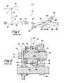
- FIG. 1 a manually operated remote control assembly 10 of the type in which the variable mechanical advantage/variable effective length torque arm assembly of the present invention is especially advantageously utilized is illustrated.
- Remote controls for change gear transmissions are well known in the prior art and are especially advantageously utilized in motor vehicles such as trucks of the "cab over engine” type which permits locating of the driver seat at the extreme front of the vehicle, thereby permitting the use of space commonly occupied by the cab for loading space.
- Remote controls of this type may be seen in greater detail by reference to United States Patent Nos. 2,040,594; 4,104,929; 4,269,282 and 4,275,612 previously mentioned above.
- remote control assembly 10 comprises a shift lever 12 which is pivotably attached at a tower assembly 14 and which has one end 16 thereof attached to a crank mechanism 18 of a control rod 20.
- Control rod 20 is supported in a support member for axial movement along its axis as indicated by arrow 22 and rotation about its axis as indicated by arrow 24 whereby rightward or leftward pivotal movement of the shift lever as indicated by arrow 26 will result in a rotational movement of control rod 24 about its axis and forward and rearward movement of shift lever 12 as indicated by arrow 28 will result in a corresponding opposite axial movement of control rod 20 in the direction of arrow 22.
- a torque arm 30 is pivotably mounted about a pivot axis transverse to the axis of control rod 20 at one end 32 thereof to the control rod 20 and is fixedly mounted at the other end 34 thereof to a shift shaft 36.
- Shift shaft 36 is supported in a shift bar housing assembly of a known type for movement along its axis in the direction of arrow 38 and rotation about its axis in the direction of arrow 40.
- the axis of shift shaft 36 is generally transverse to and spaced from the axis of control rod 20.
- Shift shaft 36 carries a shift finger 42 fixed thereto which may be aligned with the shift block members 44 carried by a plurality of generally parallel shift rails 46 extending generally transverse to the axis of shift shaft 36.
- Each of the axially movable shift rails 46 carry a shift fork 48 fixed thereto as is well known in the art.
- a rotational motion of control rod 20 will result in torque arm 30 pivoting in a plane perpendicular to the axis of control rod 20 and containing the axis of shift shaft 36 whereby an axial movement will be applied to shift shaft 36 to selectively align shift finger 42 with the shift block 44 of a selected shift rail 46.
- An axial movement of control rod 20 will result in torque arm 30 pivoting about the axis of shift shaft 36 in a plane perpendicular to the axis of shift shaft 36 thereby imparting a rotational movement to shift shaft 36 and shift finger 42 carried thereby to selectively axially move the selected shift rail 46 and shift fork 48 carried thereby.
- FIG. 2 illustrates a typical synchronized positive clutch assembly 50 for selectively engaging one of two selectable gears 52 or 54 to a driven shaft 56.
- gear 52 is fixed for rotation with a shaft 58 which may be the input shaft of a transmission or a transmission section.
- Gear 52 is constantly meshed with a countershaft gear 60 which is fixed for rotation on a countershaft 62 which additionally carries a gear 64 fixed for rotation therewith.
- Gear 64 is in constant meshing engagement with gear 54.
- Gear 54 is provided with an annular bushing 66 allowing gear 54 to rotate relative to shaft 56 when not positively clutched thereto.
- Synchronized positive clutch assembly 50 may be shifted rightwardly to engage gear 54 with shaft 56 or may be shifted leftwardly to engage gear 52 with shaft 20.
- Synchronized positive clutch assembly 50 includes a double ended axially movable clutch member 68 which is splined to shaft 56 for axial movement relative thereto and rotation therewith.
- Clutch member 68 is provided with a generally annular groove 70 for receipt of a shift fork 48 as is well known in the art.
- Gear 52 is provided with internal positive clutch teeth 72 for engagement with external clutch teeth 74 on the leftward end of clutch member 68 and gear 54 is provided with internal clutch teeth 76 for engagement with external clutch teeth 78 carried by the rightward end of clutch member 68 conical frictional clutch members 80 and 82 are carried on the leftward and rightward, respectively, ends of synchronizer pins 84 for frictional synchronizing engagement with conical frictional surfaces 86 and 88 carried by gears 52 and 54 ' respectively.
- initial axial movement of clutch 68 from the disengaged position shown will result in the synchronizer pins 84 preventing further axial movement if the positive clutch members are not at synchronous or substantially synchronous rotation and will cause the friction surfaces to engage.
- the shaft 56 and clutch member 68 which rotates therewith will be caused to rotate at a synchronous or substantially synchronous speed with the selected gear and positive clutch teeth carried thereby.
- the blocker or synchronizer pins 84 will cease to prevent further axial movement of clutch member 68 and the clutch member 68 will move through the blocked position into engagement with the selected gear.
- the initial movement of the clutch member 48 to cause the blocker to engage and to result in initial contact of the friction surfaces requires a relatively small axial movement and a relatively small axial force.
- the axial force required to engage the friction members sufficiently to bring the positive clutch members into synchronous or substantially synchronous rotation requires a relatively small axial movement (essentially compression of the friction material) but a relatively large axial force.
- further axial movement of the axially movable clutch member 68 through the blocking mechanism and into positive engagement with the selected positive clutch member requires a relatively large axial movement with a relatively small axial force.
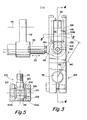
- the structure and operation of the variable mechanical advantage/variable effective length torque arm assembly 100 of the present invention may be seen in greater detail by reference to FIGS. 3-6.
- the torque arm assembly 100 is illustrated in the neutral or generally vertical position as seen in FIG. 1.
- the torque arm assembly 100 includes a generally rigid body 102 fixedly mounted at end 104 thereof to the end of the shift shaft 36 for axial and rotational movement therewith.
- the body 102 may be mounted to the end of shift shaft 36 for rotational and axial movement therewith by means of a clamping and/or spline connection or other known connecting means and the manner by which the body 102 is mounted to the shift shaft forms no part of the present invention.
- Rigid body 102 defines an axially extending elongated slot 106 extending generally transversely to the axis of control rod 20.
- the slot 106 is provided in the generally parallel biforcated upper side walls 102a and 102b of body 102 which define a second axially extending elongated slot 108 extending generally transversely to the axis of shift shaft 36 therebetween.
- Slot 106 and 108 intersect as may be seen by reference to FIG. 5.
- the upper ends of both slots 106 and 108 are defined by a cap member 110 which may be bolted to the upper end of the body 102 and may include a projection l12 defining a spring seat and guide member.
- control rod 20 is supported for axial movement and rotation about its axis by a support member 112 which may itself be pivotably mounted about a pivot axis l14 to a support structure fixed to the transmission shift bar housing assembly 116.
- An eyelet type rod end 118 is mounted to control rod 20 for rotational and axial movement therewith.
- rod end 118 could be integral with control rod 20.
- Rod end 118 is received in slot 108 and is provided with a through bore 120 into which are pressed axially outwardly flanged bushings 122.
- a pin member 124 is received within the inner bore of the bushings 122 and a roll pin 126 may be utilized to maintain the pin 124 within rod end 118.
- bushings 128 Pressed upon the outer ends of pin 124 are axially inwardly flanged bushings 128.
- the outer diameter of the flanges 130 of bushings 128 is greater than the width of slot 106 and thus maintain the rod end 118, pin 124, bushings 122 and bushings 128 assembly slidably located within slot 106.
- the hub portion of bushings 128 surrounding pin 124 are preferably of a low friction material and allow the assembly to be axially slidable in slot 106.
- a washer member 132 rests upon the upper surface of rod end 118 and provides a spring seat for a compression spring 134 compressed between the spring seat and guide 112 and washer 132 to urge the rod end 118 downwardly in slot 106.
- a resilient bumper member 136 may be provided at the bottom of slot 106 to prevent damage to the rod end 118.
- Rod end l18 is received ithrough slot 108 while pin member 124 and bushings 128 are slidably received within slot 106.
- the axial separation of the axialy outer surfaces of bushings 128 is generally equal to the width of slot 108 whereby a rotation of control rod 20 and rod end 118 about the axis of control rod 20 will impart a pivotal movement of body 102 about the axis of control rod 20.
- torque arm assembly 100 when imparting a rotational movement to shift shaft 36, torque arm assembly 100, where the rod end is in the resiliently biased position at the bottom end of slot 106 defines a effective torque arm length 138 measured from the rotational axis of shift shaft 36 to the pivot axis of rod end 118.
- the bias of spring 134 will be overcome and the rod end 118, pin 124 and bushing 128 will slide upwardly against the bias of spring 134 to obtain an increased mechanical advantage by increasing the effective length of torque arm 110 to a effective length 140.
- spring 134 will force rod end 118 and pin member 124 downwardly in slot 106 to achieve a greater rotational movement of shift shaft 36 without requiring any significant increase in axial movement of control rod 20.
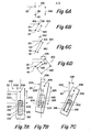
- FIGS. 6A-6D The operation and advantages of the variable mechanical advantage/variable effective length torque arm assembly 100 is schematically illustrated in FIGS. 6A-6D.
- the torque arm assembly 100 is illustrated in the neutral position whereat the shift shaft 36 and shift finger 42 are substantially vertical and have not engaged a shift block structure of a selected shift rail and thus shift fork 48 and sliding clutch member 68 is axially centered relative to clutch teeth 72 and 76.
- shift shaft 36 and shift finger 42 must be pivoted in a generally clockwise direction to engage and axially move the shift rail 46 and shift fork 48 in a generally leftward axial direction.
- the operation of torque arm 100 in the first segment of axial movement of shift fork 48 is illustrated in FIG.
- torque arm 100 in the second segment of axial movement of shift fork 48 and shift rail 46 is illustrated in FIG. 6C and comprises movement of shift fork 48 axially leftwardly to apply a relatively high axial force to the synchronizer clutch friction surfaces to cause the positive clutch members 72 and 74 to rotate at a substantially synchronous speed.
- the rod end 118 will move in slot 106 of body 102 away from shift shaft axis 36 to define a second longer effective length 140 and increased mechanical advantage associated therewith.
- control rod 20 requires little or no additional axial movement of control rod 20.
- Arrow 144 illustrates the amount of axial movement of control rod 20 which would be required to rotate the shift shaft 36 and shift finger 42 to the position shown in FIG. 7D if a fixed mechanical advantage/fixed effective torque arm length torque arm assembly having an effecitve length 140 were utilized in place of the variable mechanical advantage/variable effective length torque arm assembly 100 of the present invention.
- the amount of axial movement of control rod 20 not required as a result of utilizing the torque arm assembly 100 of the present invention is substantial.
- FIGS. 7A-7C illustrate a variable mechanical advantage/variable effective length torque arm assembly 200 utilized to convert axial movement of a control rod 20 into rotational movement of a selectively rotatable member 202 pivotable about its axis 204.
- control rod 20 is pivotably mounted at pivot point 206 at end 208 of a rigid body 210 of the torque arm assembly 200.
- Pivot point 206 defines a pivot axis substantially parallel to axis of rotation 204 of member 202.
- Rigid body 210 is provided with an axially extending elongated slot 212 in which the end 214 of member 202 is slidably but nonrotationally received.
- the end 214 of rotatable member 202 is provided with substantially flat sides which are slidably but nonrotatably engaged with flat side walls 216 defining the slot 212.
- a compression biasing spring 218 biases the member 202 to the end 220 of slot 212 closest to pivot point 206 to define a torque arm having an effective length 222. If the resistance to rotation of member 202 is insufficient to overcome the bias of spring 218 the torque arm assembly 200 will operate in the condition shown in FIGS. 7A.
- the present invention provides an improved torque arm assembly having a variable mechanical advantage/variable effective length.
- the variable mechanical advantage/variable effective length torque arm assembly of the present invention is especially advantageous when utilized in connection with a mechanism for shifting a synchronized mechanical transmission wherein the assembly provides the advantages of a relatively longer effective length torque arm for increased mechanical advantage during the segment of the shift operation requiring exertion of substantial force, namely that segment during which the synchronizing clutches are being engaged and also provides the advantage of a relatively shorter effective length for final axial movement of the shift rail and shift fork to the fully engaged position of the selected positive clutch while requiring little if any additional axial movement of the control rod member.
Landscapes
- Engineering & Computer Science (AREA)
- General Engineering & Computer Science (AREA)
- Mechanical Engineering (AREA)
- Gear-Shifting Mechanisms (AREA)
- Shafts, Cranks, Connecting Bars, And Related Bearings (AREA)
Applications Claiming Priority (2)
| Application Number | Priority Date | Filing Date | Title |
|---|---|---|---|
| US436137 | 1982-10-22 | ||
| US06/436,137 US4502346A (en) | 1982-10-22 | 1982-10-22 | Variable mechanical advantage torque arm |
Publications (2)
| Publication Number | Publication Date |
|---|---|
| EP0110520A2 true EP0110520A2 (de) | 1984-06-13 |
| EP0110520A3 EP0110520A3 (de) | 1985-09-25 |
Family
ID=23731252
Family Applications (1)
| Application Number | Title | Priority Date | Filing Date |
|---|---|---|---|
| EP83305932A Withdrawn EP0110520A3 (de) | 1982-10-22 | 1983-09-30 | Hebelarm mit veränderbarer mechanischer Übersetzung |
Country Status (4)
| Country | Link |
|---|---|
| US (1) | US4502346A (de) |
| EP (1) | EP0110520A3 (de) |
| JP (1) | JPS5993508A (de) |
| ES (1) | ES8407222A1 (de) |
Cited By (1)
| Publication number | Priority date | Publication date | Assignee | Title |
|---|---|---|---|---|
| DE3714637A1 (de) * | 1987-05-02 | 1988-12-08 | Peter Dipl Ing Hoffmann | Drehmoment-ausgleichssystem |
Families Citing this family (4)
| Publication number | Priority date | Publication date | Assignee | Title |
|---|---|---|---|---|
| JP2557722Y2 (ja) * | 1991-11-01 | 1997-12-17 | 三菱自動車工業株式会社 | シンクロメッシュ装置 |
| GB9225890D0 (en) * | 1992-12-11 | 1993-02-03 | Eaton Corp | Downshift inhibitor |
| US20060185464A1 (en) * | 2005-02-22 | 2006-08-24 | Borgwarner Inc. | Rotary actuator |
| FR2900213B1 (fr) * | 2006-04-24 | 2008-12-12 | Renault Sas | Dispositif d'assistance au passage des vitesses sur boite de vitesses manuelle |
Family Cites Families (20)
| Publication number | Priority date | Publication date | Assignee | Title |
|---|---|---|---|---|
| CA599088A (en) * | 1960-05-31 | Collins Radio Company | In-line reversing mechanism | |
| US763548A (en) * | 1903-08-21 | 1904-06-28 | Frank A Ferguson | Two-speed reversing-gear. |
| US787418A (en) * | 1904-04-19 | 1905-04-18 | Entpr Machine Company | Reversible driving mechanism. |
| US1099464A (en) * | 1913-01-31 | 1914-06-09 | Ames A Olson | Two-speed gearing. |
| US1138718A (en) * | 1913-10-21 | 1915-05-11 | Alfred N Adams | Reversing-gearing. |
| GB383375A (en) * | 1931-02-03 | 1932-11-17 | Snow & Petrelli Mfg Co | Improvements in or relating to reverse gears |
| CH169208A (de) * | 1933-04-21 | 1934-05-15 | Rothen Hans | Kraftübertragungsgestänge, insbesondere für Bremsen. |
| US2040594A (en) * | 1934-02-24 | 1936-05-12 | Fuller Mfg Co | Remote control for transmissions |
| US2385734A (en) * | 1941-10-11 | 1945-09-25 | Davenport Machine Tool Co Inc | Clutch operating means |
| US2414832A (en) * | 1944-01-13 | 1947-01-28 | Borg Warner | Planetary reverse gear |
| FR981341A (fr) * | 1948-12-29 | 1951-05-24 | Vehicules Et Tracteurs Electr | Perfectionnements aux dispositifs de commande de timoneries |
| US2900970A (en) * | 1958-02-17 | 1959-08-25 | Caterpillar Tractor Co | Single lever control for engine starting mechanism |
| DE1480678B2 (de) * | 1963-06-26 | 1976-07-15 | Zahnradfabrik Friedrichshafen AG, 7990 Friednchshafen | Fernschalteinrichtung fuer wechselgetriebe von kraftfahrzeugen |
| US3221851A (en) * | 1963-10-16 | 1965-12-07 | Eaton Mfg Co | Synchronized positive clutches |
| GB1408311A (en) * | 1972-03-17 | 1975-10-01 | Turner Mfg Co Ltd | Control mechanisms for gear boxes |
| IT1024546B (it) * | 1974-04-17 | 1978-07-20 | Fasano Osvaldo | Leva a variazione di coppia, causa ta dal aumento della forza resistente delle pompe freno e meccanismi souivalenti degli automezzi esinili |
| US4104929A (en) * | 1977-05-02 | 1978-08-08 | Dana Corporation | Shift mechanism |
| GB1572317A (en) * | 1978-03-30 | 1980-07-30 | Eaton Ltd | Shift control for change speed gear transmission for vehicles |
| US4269282A (en) * | 1979-05-31 | 1981-05-26 | Mack Trucks, Inc. | Gear shift control |
| DE3219934C2 (de) * | 1982-05-27 | 1986-06-12 | M.A.N. Maschinenfabrik Augsburg-Nürnberg AG, 8000 München | Schalteinrichtung für ein Kraftfahrzeug |
-
1982
- 1982-10-22 US US06/436,137 patent/US4502346A/en not_active Expired - Fee Related
-
1983
- 1983-09-30 EP EP83305932A patent/EP0110520A3/de not_active Withdrawn
- 1983-10-20 ES ES526588A patent/ES8407222A1/es not_active Expired
- 1983-10-22 JP JP58198956A patent/JPS5993508A/ja active Pending
Cited By (1)
| Publication number | Priority date | Publication date | Assignee | Title |
|---|---|---|---|---|
| DE3714637A1 (de) * | 1987-05-02 | 1988-12-08 | Peter Dipl Ing Hoffmann | Drehmoment-ausgleichssystem |
Also Published As
| Publication number | Publication date |
|---|---|
| US4502346A (en) | 1985-03-05 |
| JPS5993508A (ja) | 1984-05-30 |
| ES526588A0 (es) | 1984-08-16 |
| EP0110520A3 (de) | 1985-09-25 |
| ES8407222A1 (es) | 1984-08-16 |
Similar Documents
| Publication | Publication Date | Title |
|---|---|---|
| US4938088A (en) | Vehicle transmissions | |
| US4369867A (en) | Automatic transmission parking brake mechanism | |
| US4770280A (en) | Snap-action arrangement for transfer case synchronizer | |
| DE69710554T2 (de) | Synchronisierte Bereichsschalteinrichtung für zweistufiges Verteilergetriebe | |
| US6220109B1 (en) | Method and apparatus for actuating a transmission | |
| US4601214A (en) | Gear-shift mechanism for manual transmission | |
| US4515029A (en) | Compound variable mechanical advantage shifting mechanism | |
| EP1334297B1 (de) | Stellvorrichtung für ein einstellbares getriebe | |
| US5076112A (en) | Easy shift sector for transfer case | |
| US4348913A (en) | Transmission for a vehicle | |
| US5121649A (en) | Motorized gear shift control apparatus for a transmission gearbox, in particular for automotive vehicles | |
| US3805635A (en) | Remote control linkage for automotive transmission | |
| DE69501972T2 (de) | Gangschaltmechanismus für ein Getriebe | |
| US4502346A (en) | Variable mechanical advantage torque arm | |
| US4497396A (en) | Variable mechanical advantage shift lever | |
| DE19700936A1 (de) | Vorrichtung zur Betätigung eines betätigbaren Bauteiles | |
| US4846322A (en) | Park position shift selector mechanism and method | |
| DE102005054420B4 (de) | Verfahren zur Steuerung einer Parksperrvorrichtung eines Fahrzeuges mit Automatikgetriebe | |
| US5607037A (en) | Springs for vehicle transmission synchronizer | |
| US4509624A (en) | Parking brake safety mechanism for automatic transmissions | |
| US2516850A (en) | Planetary shift mechanism | |
| US3971265A (en) | Manual automotive transmission | |
| MXPA96005876A (en) | Springs for a transmission synchronizer of a vehic | |
| DE102006022848A1 (de) | Stufenlos veränderliches Getriebesystem | |
| DE19929941A1 (de) | Synchronisiereinrichtung |
Legal Events
| Date | Code | Title | Description |
|---|---|---|---|
| PUAI | Public reference made under article 153(3) epc to a published international application that has entered the european phase |
Free format text: ORIGINAL CODE: 0009012 |
|
| AK | Designated contracting states |
Designated state(s): DE FR GB SE |
|
| PUAL | Search report despatched |
Free format text: ORIGINAL CODE: 0009013 |
|
| AK | Designated contracting states |
Designated state(s): DE FR GB SE |
|
| STAA | Information on the status of an ep patent application or granted ep patent |
Free format text: STATUS: THE APPLICATION IS DEEMED TO BE WITHDRAWN |
|
| 18D | Application deemed to be withdrawn |
Effective date: 19860526 |
|
| RIN1 | Information on inventor provided before grant (corrected) |
Inventor name: REYNOLDS, JOSEPH DOUGLAS |