EP0111186A2 - Dispositif de fermeture pour des parties mécaniques mobiles - Google Patents
Dispositif de fermeture pour des parties mécaniques mobiles Download PDFInfo
- Publication number
- EP0111186A2 EP0111186A2 EP83111484A EP83111484A EP0111186A2 EP 0111186 A2 EP0111186 A2 EP 0111186A2 EP 83111484 A EP83111484 A EP 83111484A EP 83111484 A EP83111484 A EP 83111484A EP 0111186 A2 EP0111186 A2 EP 0111186A2
- Authority
- EP
- European Patent Office
- Prior art keywords
- lock
- locks
- door
- locking system
- operating
- Prior art date
- Legal status (The legal status is an assumption and is not a legal conclusion. Google has not performed a legal analysis and makes no representation as to the accuracy of the status listed.)
- Granted
Links
- 230000000903 blocking effect Effects 0.000 claims abstract description 13
- 238000000034 method Methods 0.000 claims description 9
- 230000006870 function Effects 0.000 claims description 4
- 230000008569 process Effects 0.000 claims description 3
- 230000009471 action Effects 0.000 claims description 2
- 230000007547 defect Effects 0.000 claims 2
- 238000013270 controlled release Methods 0.000 claims 1
- 238000005259 measurement Methods 0.000 claims 1
- 238000003860 storage Methods 0.000 abstract description 2
- 238000007747 plating Methods 0.000 abstract 1
- 230000007246 mechanism Effects 0.000 description 11
- 230000000694 effects Effects 0.000 description 4
- 238000011017 operating method Methods 0.000 description 4
- 230000001681 protective effect Effects 0.000 description 4
- 230000008859 change Effects 0.000 description 3
- 230000008901 benefit Effects 0.000 description 2
- 230000001419 dependent effect Effects 0.000 description 2
- 238000005553 drilling Methods 0.000 description 2
- 230000007935 neutral effect Effects 0.000 description 2
- 230000000737 periodic effect Effects 0.000 description 2
- 230000002159 abnormal effect Effects 0.000 description 1
- 230000002547 anomalous effect Effects 0.000 description 1
- 230000004888 barrier function Effects 0.000 description 1
- 230000006399 behavior Effects 0.000 description 1
- 238000010276 construction Methods 0.000 description 1
- 229910052593 corundum Inorganic materials 0.000 description 1
- 239000010431 corundum Substances 0.000 description 1
- 238000005336 cracking Methods 0.000 description 1
- 238000005520 cutting process Methods 0.000 description 1
- 230000006378 damage Effects 0.000 description 1
- 238000001514 detection method Methods 0.000 description 1
- 238000005516 engineering process Methods 0.000 description 1
- 230000006872 improvement Effects 0.000 description 1
- 230000003993 interaction Effects 0.000 description 1
- 239000002184 metal Substances 0.000 description 1
- 239000000203 mixture Substances 0.000 description 1
- 238000011022 operating instruction Methods 0.000 description 1
- 230000002093 peripheral effect Effects 0.000 description 1
- 230000002085 persistent effect Effects 0.000 description 1
- 238000002360 preparation method Methods 0.000 description 1
- 230000008672 reprogramming Effects 0.000 description 1
- 230000000717 retained effect Effects 0.000 description 1
- 238000010187 selection method Methods 0.000 description 1
- 230000003068 static effect Effects 0.000 description 1
Images

Classifications
-
- E—FIXED CONSTRUCTIONS
- E05—LOCKS; KEYS; WINDOW OR DOOR FITTINGS; SAFES
- E05B—LOCKS; ACCESSORIES THEREFOR; HANDCUFFS
- E05B65/00—Locks or fastenings for special use
- E05B65/0075—Locks or fastenings for special use for safes, strongrooms, vaults, fire-resisting cabinets or the like
-
- G—PHYSICS
- G07—CHECKING-DEVICES
- G07C—TIME OR ATTENDANCE REGISTERS; REGISTERING OR INDICATING THE WORKING OF MACHINES; GENERATING RANDOM NUMBERS; VOTING OR LOTTERY APPARATUS; ARRANGEMENTS, SYSTEMS OR APPARATUS FOR CHECKING NOT PROVIDED FOR ELSEWHERE
- G07C9/00—Individual registration on entry or exit
- G07C9/00174—Electronically operated locks; Circuits therefor; Nonmechanical keys therefor, e.g. passive or active electrical keys or other data carriers without mechanical keys
- G07C9/00658—Electronically operated locks; Circuits therefor; Nonmechanical keys therefor, e.g. passive or active electrical keys or other data carriers without mechanical keys operated by passive electrical keys
- G07C9/00674—Electronically operated locks; Circuits therefor; Nonmechanical keys therefor, e.g. passive or active electrical keys or other data carriers without mechanical keys operated by passive electrical keys with switch-buttons
- G07C9/0069—Electronically operated locks; Circuits therefor; Nonmechanical keys therefor, e.g. passive or active electrical keys or other data carriers without mechanical keys operated by passive electrical keys with switch-buttons actuated in a predetermined sequence
-
- G—PHYSICS
- G07—CHECKING-DEVICES
- G07C—TIME OR ATTENDANCE REGISTERS; REGISTERING OR INDICATING THE WORKING OF MACHINES; GENERATING RANDOM NUMBERS; VOTING OR LOTTERY APPARATUS; ARRANGEMENTS, SYSTEMS OR APPARATUS FOR CHECKING NOT PROVIDED FOR ELSEWHERE
- G07C9/00—Individual registration on entry or exit
- G07C9/00174—Electronically operated locks; Circuits therefor; Nonmechanical keys therefor, e.g. passive or active electrical keys or other data carriers without mechanical keys
- G07C9/00896—Electronically operated locks; Circuits therefor; Nonmechanical keys therefor, e.g. passive or active electrical keys or other data carriers without mechanical keys specially adapted for particular uses
- G07C9/00912—Electronically operated locks; Circuits therefor; Nonmechanical keys therefor, e.g. passive or active electrical keys or other data carriers without mechanical keys specially adapted for particular uses for safes, strong-rooms, vaults or the like
Definitions
- the invention is in the field of security technology and relates to a locking system for movable mechanical closures, in particular to an arrangement for armored doors with door / frame bolts, locking bars and locking bars which can be locked by the locking mechanism and act on the locking bars.
- Movable mechanical closures are devices that temporarily release and temporarily block an opening, such as e.g. B. Doors of all kinds (hinged doors, sliding doors, revolving doors, folding doors, lattice doors, etc.), windows, lids and barriers.
- a known mechanical vulnerability can be found e.g. B. on the locking rod for bolt actuation.
- the locking bar connects a bolt or a bolt bar provided with several bolts to the locking point of the lock.
- the locking points must be specially protected, for example by covering the lock and locking point by means of particularly hard cover plates which resist drilling, such as, for example, mixing plates of a corundum metal mixture.
- the location of the blocking points which should normally be unknown, will be within a range of what is possible, as one knows the location of the lock, and the location of the lock is determined within certain limits by the lock opening device on the outside of the armored door.
- the number of locks and therefore also the locking points is very limited, because each lock requires a connecting element that leads directly out through a hole in the armor, and an operating element on the outside that indicates the position of the lock and locking point.
- the combination locks used in security locks can be determined by a code which can be defined inside the lock in the form of a very specific, predetermined combination of a number of coding disks, i.e. H.
- the combination lock is now actuated in the case of a properly locked security lock, for example an armored door, in the sense of decoding the coding disks in any angular position relative to one another, this is nothing more than a targeted arrangement of the positions of all unlocking points on the coding disk. If this ordering is carried out according to the recipe and the lock mechanism can be actuated by "internal" unlocking to open, the order of the coding disks brought about by opening is or is frozen as it were. This state does not simply disappear after the door is closed again, the order must be removed in a very targeted manner, and the expert speaks of code rejection. Discarding the code, which unfortunately often happens in practice, must not be forgotten; because the can ierusionn d in parent Ko by means Rie gently open the tightly closed door again.
- Correct discarding of the opening code comprises the mixing of the state of each individual and all coding disks, of which a majority, for example three to four in number, can be used.
- a fleeting discarding can perhaps twist the release groove of a single pane by perhaps only ten degrees, with the effect that the door is probably closed and locked, but can be unlocked and opened again by simple, skillful exploitation of this fact with a small turn of the combination button.
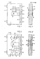
- the armored door 1 is shown in a front view without the always necessary frame area.
- two door hinges of the usual type are indicated as two rectangles 11.
- the locking bar 15 can be moved together with the locking bars 12; this movement is transmitted to the locking bar 15 with the aid of a locking drive 30.
- the lock mechanism 20, which is already known in any case, is only represented by a dashed square and a circle in it, which circle an operating device 25 is to indicate, for example a number combination button or even simply a keyhole with an associated key.
- the locking rod 13 is connected on the one hand at point 13 to the locking bar 15 and articulated on the other side to the locking point 14.
- the lock Point 14 blocks or releases the locking bar 13 and is advantageously protected behind the armor 22.
- FIG. 2 again shows in a very simplified manner an armored door 1 with a locking bar 15 carrying the bolts 12 and two hinges 11, a lock 20, the mechanism of which is connected to the locking beam 15 via a locking rod 13.
- blocking point coordinates 14 l ... 14 ... 14 distributed over large parts of the door area which of course extend in any order or disorder over the door area.
- a blocking point coordinate is now selected by means of an optional selection method, in the present case the blocking point coordinate 14 m, in the area of which the lock 20 is placed.
- the functioning of this measure naturally presupposes that there are no longer any direct bushings to the outside of the door for actuating the lock.
- the lock 20 is therefore operated remotely by electrical means.
- the door hinges can be used to ensure that cables for the power supply line from the outside to the interior of the door meet the desired security.
- the locks 20 shown in FIG. 2 'and arranged at different locations 14 index, the electrical feed lines 40 which start from these locks and which connect the operating device 25, and also the operating device 25 itself, can also be present several times and not only individually. This means that, for example, the location 14 m and a further location 14 could be occupied by a lock at the same time, two locking bars 13 also acting on the locking bar at the same time, so that two or even one operating device could be used Alternatively, unlock the two locks and thus release the locking bar to open the door.
- Figure 3 now shows a schematic representation of the elements that can be used for an electrical remote control of the mechanism for "internal" locking and unlocking. Since the ordering of the code is no longer done mechanically by turning a combination button, but is carried out mechanically decoupled, there is no longer any need to store the code in the lock mechanism itself, to store it mechanically, and on the other hand if electronic storage means are already provided storing the opening code in it is advantageous to use the uP solution.
- a typical schematic representation of a microprocessor with typical wiring can be seen on the right in FIG it remains open whether, for example, the program memory is used or whether an operating program is implemented in terms of hardware using a simple logic network.
- the data memory is used, for example, to record the opening or closing code and other data, the use of which increases security.
- An input / output circuit finally connects the processor to the periphery, which now includes one or more mechanical terminations.
- the armored door according to FIG. 2 is shown again in this example. Through a door hinge 11, the electrical leads lead to the lock 20, in the interior of which a motor-operated mechanism for "internal" unlocking is activated. If the lock 20 is then, as it were, open, the "outer" lock formed by the bolt 12 with the door frame can be released with the aid of a bolt drive 30. The door is also open.
- an input keypad 35 can be used to enter the opening code. For example, status messages, memory contents, etc. would be displayed on a display 34 as usual.
- FIG. 4 now shows an embodiment according to the general wiring in FIG. 3, in which the microprocessor with the memory for the application program and the memory for the key data and the I / O network are arranged within the door area 1, that is to say within the security zone is.
- From the I / O circuit leads lead through the hinge 11 to a keyboard 35 lying outside the door area, which keyboard is connected through the leads 40 to the electronics in the door area.
- An electrical supply line 50 leads from the I / O network to the lock actuation and converts electrical values into a mechanical drive.
- This lock actuation can be, for example, a motor for a rotary solution or a magnet for a translatory solution.
- the electrical operating variables are generated for the lock actuation.
- the operating procedure is designed in such a way that only dynamic processes of a predetermined specificity have an effect. Static states should have no effect on the lock actuation.
- AC motors for example, which are controlled with these operating variables, are used as the lock actuation.
- the control is designed for frequency-dependent operation, for example, so that the torque band of the motor can be used specifically in this solution. It should therefore not be possible, as is the case, for example, in the case of a DC motor, that a voltage level of the same polarity which persists over a long period of time could activate the lock actuation. This is no longer the case with frequency-dependent operation, and, as has already been mentioned before, only dynamic electrical variables that correspond to the predetermined parameters can cause a door opening. Any other condition keeps the mechanical closure closed for safety reasons.
- the lock is locked automatically, whereby an automatic closing of the door can also be included.
- the redundancy for security can be increased quickly and easily, for example by assigning a third, fourth, etc. code, which is not possible with the mechanical coding lock.
- the intelligence involved allows a number of variants without a mandatory measure to change the locking system.
- a blocking point to be put out of action is always behind protective armor layers, in the area of which the lock is also located, without the blocking point area being able to be estimated, as in the known prior art.
Landscapes
- Physics & Mathematics (AREA)
- General Physics & Mathematics (AREA)
- Lock And Its Accessories (AREA)
Priority Applications (1)
| Application Number | Priority Date | Filing Date | Title |
|---|---|---|---|
| AT83111484T ATE74394T1 (de) | 1982-12-03 | 1983-11-17 | Schliesssystem fuer bewegliche mechanische abschluesse. |
Applications Claiming Priority (2)
| Application Number | Priority Date | Filing Date | Title |
|---|---|---|---|
| CH7056/82 | 1982-12-03 | ||
| CH705682 | 1982-12-03 |
Publications (3)
| Publication Number | Publication Date |
|---|---|
| EP0111186A2 true EP0111186A2 (fr) | 1984-06-20 |
| EP0111186A3 EP0111186A3 (en) | 1986-03-19 |
| EP0111186B1 EP0111186B1 (fr) | 1992-04-01 |
Family
ID=4319238
Family Applications (1)
| Application Number | Title | Priority Date | Filing Date |
|---|---|---|---|
| EP83111484A Expired - Lifetime EP0111186B1 (fr) | 1982-12-03 | 1983-11-17 | Dispositif de fermeture pour des parties mécaniques mobiles |
Country Status (5)
| Country | Link |
|---|---|
| EP (1) | EP0111186B1 (fr) |
| JP (1) | JPH061016B2 (fr) |
| AT (1) | ATE74394T1 (fr) |
| CA (1) | CA1225250A (fr) |
| DE (1) | DE3382539D1 (fr) |
Cited By (5)
| Publication number | Priority date | Publication date | Assignee | Title |
|---|---|---|---|---|
| EP0329931A3 (fr) * | 1988-02-22 | 1990-03-14 | BKS GmbH | Installation électromécanique de fermeture de porte |
| FR2666614A1 (fr) * | 1990-09-11 | 1992-03-13 | Telia | Dispositif de commande d'ouverture de portes, notamment de coffres-forts et, en general, de toutes portes fortes. |
| US5196841A (en) * | 1982-12-03 | 1993-03-23 | Bauer Ag | Vault door locking system featuring microprocessor-based locking means with redundancy control override |
| DE4426902A1 (de) * | 1993-09-16 | 1995-03-23 | Btv S A | Elektronisches Schloß bzw. Türöffner für Magnetkarten |
| CN113689597A (zh) * | 2021-08-26 | 2021-11-23 | 珠海格力电器股份有限公司 | 门锁的开锁控制方法、装置、存储介质、处理器及门锁 |
Families Citing this family (5)
| Publication number | Priority date | Publication date | Assignee | Title |
|---|---|---|---|---|
| JP4871627B2 (ja) * | 2006-04-04 | 2012-02-08 | 株式会社 エピア | エアバッグ付のダンボール、紙製容器等の梱包容器 |
| CN106013988B (zh) * | 2016-07-20 | 2019-06-11 | 海门市彼维知识产权服务有限公司 | 具有伸缩触发件的锁闭结构 |
| CN106014000B (zh) * | 2016-07-20 | 2019-07-12 | 南通市台盈新材料科技有限公司 | 保险箱锁合套件 |
| CN106050009B (zh) * | 2016-07-20 | 2019-05-14 | 赵金 | 药品储存箱 |
| US11661787B2 (en) * | 2020-03-27 | 2023-05-30 | JVA Partners | Safe and lock detection system |
Citations (2)
| Publication number | Priority date | Publication date | Assignee | Title |
|---|---|---|---|---|
| EP0021670A1 (fr) | 1979-06-07 | 1981-01-07 | Bjoern Lyng | Serrure à permutation notamment pour coffres-forts |
| CH629565A5 (de) | 1978-05-03 | 1982-04-30 | Bauer Kassenfabrik Ag | Schalteinrichtung zur kontrolle der schliessstellung einer fluegeltuere. |
Family Cites Families (8)
| Publication number | Priority date | Publication date | Assignee | Title |
|---|---|---|---|---|
| FR1600310A (fr) * | 1968-12-31 | 1970-07-20 | ||
| US3881171A (en) * | 1973-12-03 | 1975-04-29 | Mosler Safe Co | Vault protected with electronic time and combination lock |
| JPS598242Y2 (ja) * | 1974-07-09 | 1984-03-14 | 株式会社小糸製作所 | 2輪自動車用シ−ルドビ−ム形電球 |
| DE2506007A1 (de) * | 1975-02-13 | 1976-08-19 | Mueller Gerhard Kg | Schloss fuer tueren, insbesondere fuer tresore, wert- und kassenschraenke |
| JPS6031990B2 (ja) * | 1978-12-13 | 1985-07-25 | 株式会社熊平製作所 | 金庫扉の錠止め機構 |
| JPS5628286U (fr) * | 1979-08-09 | 1981-03-17 | ||
| JPS5629078A (en) * | 1979-08-20 | 1981-03-23 | Hitachi Ltd | Filter for pump |
| JPS5651157U (fr) * | 1979-09-19 | 1981-05-07 |
-
1983
- 1983-11-17 EP EP83111484A patent/EP0111186B1/fr not_active Expired - Lifetime
- 1983-11-17 DE DE8383111484T patent/DE3382539D1/de not_active Expired - Fee Related
- 1983-11-17 AT AT83111484T patent/ATE74394T1/de not_active IP Right Cessation
- 1983-11-23 CA CA000441779A patent/CA1225250A/fr not_active Expired
- 1983-12-02 JP JP58229029A patent/JPH061016B2/ja not_active Expired - Lifetime
Patent Citations (2)
| Publication number | Priority date | Publication date | Assignee | Title |
|---|---|---|---|---|
| CH629565A5 (de) | 1978-05-03 | 1982-04-30 | Bauer Kassenfabrik Ag | Schalteinrichtung zur kontrolle der schliessstellung einer fluegeltuere. |
| EP0021670A1 (fr) | 1979-06-07 | 1981-01-07 | Bjoern Lyng | Serrure à permutation notamment pour coffres-forts |
Cited By (6)
| Publication number | Priority date | Publication date | Assignee | Title |
|---|---|---|---|---|
| US5196841A (en) * | 1982-12-03 | 1993-03-23 | Bauer Ag | Vault door locking system featuring microprocessor-based locking means with redundancy control override |
| EP0329931A3 (fr) * | 1988-02-22 | 1990-03-14 | BKS GmbH | Installation électromécanique de fermeture de porte |
| FR2666614A1 (fr) * | 1990-09-11 | 1992-03-13 | Telia | Dispositif de commande d'ouverture de portes, notamment de coffres-forts et, en general, de toutes portes fortes. |
| EP0475866A1 (fr) * | 1990-09-11 | 1992-03-18 | Societe A Responsabilite Limitee Dite: T.E.L.I.A. | Dispositif de commande d'ouverture de portes, notamment de coffres-forts et, en général, de toutes portes fortes |
| DE4426902A1 (de) * | 1993-09-16 | 1995-03-23 | Btv S A | Elektronisches Schloß bzw. Türöffner für Magnetkarten |
| CN113689597A (zh) * | 2021-08-26 | 2021-11-23 | 珠海格力电器股份有限公司 | 门锁的开锁控制方法、装置、存储介质、处理器及门锁 |
Also Published As
| Publication number | Publication date |
|---|---|
| DE3382539D1 (de) | 1992-05-07 |
| CA1225250A (fr) | 1987-08-11 |
| JPH061016B2 (ja) | 1994-01-05 |
| JPS59109677A (ja) | 1984-06-25 |
| EP0111186B1 (fr) | 1992-04-01 |
| EP0111186A3 (en) | 1986-03-19 |
| ATE74394T1 (de) | 1992-04-15 |
Similar Documents
| Publication | Publication Date | Title |
|---|---|---|
| DE3853571T2 (de) | Elektronisches Sicherheitsschloss. | |
| EP0824624B1 (fr) | Dispositif de securite pour la fermeture d'une porte d'une armoire de commande, d'un habillage de machine ou analogue | |
| EP0111186B1 (fr) | Dispositif de fermeture pour des parties mécaniques mobiles | |
| EP0720136A2 (fr) | Dispositif pour armer un système d'alarme et pour surveiller une porte d'entrée | |
| DE2902193A1 (de) | Sicherheitsschloss | |
| DE3304304C3 (de) | System zur gemeinsamen Verriegelung und/oder Entriegelung einer Mehrzahl von Schlössern | |
| DE19527801A1 (de) | Schließsystem | |
| DE19602438C2 (de) | Kombinationsschloß | |
| EP1908899A2 (fr) | Système de verrouillage | |
| DE4244414A1 (fr) | ||
| DE2400550A1 (de) | Variable schliessvorrichtung | |
| EP0848122B1 (fr) | Elément d'actionnement rétroadaptable et système de sécurité avec élément d'actionnement | |
| DE3817308C1 (fr) | ||
| EP2686512B1 (fr) | Armoire de sécurité, en particulier armoire pour substances dangereuses | |
| DE29923398U1 (de) | Schließsystem für Möbel | |
| EP0000744B1 (fr) | Coffre-fort pour dépot de clés | |
| DE19518491C2 (de) | Anordnung aus zwei Schließzylindern für abzusichernde Zugangsbereiche | |
| DE3503933C2 (fr) | ||
| EP3396641B1 (fr) | Installation de fermeture | |
| DE2045339A1 (de) | Elektrisches Schaltschloß | |
| CH667126A5 (en) | Combined mechanical and electrical security door lock - includes mechanical and electronic number combination locks coupled to common locking mechanism | |
| DE9216137U1 (de) | Multifunktionsbefehlseinrichtung | |
| DE102004011762B3 (de) | Gehäuse für die Elektroinstallation | |
| EP0678638B1 (fr) | Serrure électromécanique | |
| EP0989267A2 (fr) | Dispositif de verrouillage et porte avec un tel dispositif |
Legal Events
| Date | Code | Title | Description |
|---|---|---|---|
| PUAI | Public reference made under article 153(3) epc to a published international application that has entered the european phase |
Free format text: ORIGINAL CODE: 0009012 |
|
| AK | Designated contracting states |
Designated state(s): AT BE CH DE FR GB IT LI LU NL SE |
|
| PUAL | Search report despatched |
Free format text: ORIGINAL CODE: 0009013 |
|
| AK | Designated contracting states |
Kind code of ref document: A3 Designated state(s): AT BE CH DE FR GB IT LI LU NL SE |
|
| 17P | Request for examination filed |
Effective date: 19860401 |
|
| 17Q | First examination report despatched |
Effective date: 19870702 |
|
| RAP1 | Party data changed (applicant data changed or rights of an application transferred) |
Owner name: BAUER AG |
|
| GRAA | (expected) grant |
Free format text: ORIGINAL CODE: 0009210 |
|
| RAP1 | Party data changed (applicant data changed or rights of an application transferred) |
Owner name: BAUER SYSTEMTECHNIK AG |
|
| ITF | It: translation for a ep patent filed | ||
| AK | Designated contracting states |
Kind code of ref document: B1 Designated state(s): AT BE CH DE FR GB IT LI LU NL SE |
|
| REF | Corresponds to: |
Ref document number: 74394 Country of ref document: AT Date of ref document: 19920415 Kind code of ref document: T |
|
| REF | Corresponds to: |
Ref document number: 3382539 Country of ref document: DE Date of ref document: 19920507 |
|
| GBT | Gb: translation of ep patent filed (gb section 77(6)(a)/1977) | ||
| ET | Fr: translation filed | ||
| PLBE | No opposition filed within time limit |
Free format text: ORIGINAL CODE: 0009261 |
|
| STAA | Information on the status of an ep patent application or granted ep patent |
Free format text: STATUS: NO OPPOSITION FILED WITHIN TIME LIMIT |
|
| 26N | No opposition filed | ||
| EPTA | Lu: last paid annual fee | ||
| EAL | Se: european patent in force in sweden |
Ref document number: 83111484.8 |
|
| PGFP | Annual fee paid to national office [announced via postgrant information from national office to epo] |
Ref country code: CH Payment date: 19990204 Year of fee payment: 16 |
|
| PGFP | Annual fee paid to national office [announced via postgrant information from national office to epo] |
Ref country code: GB Payment date: 19990504 Year of fee payment: 16 Ref country code: SE Payment date: 19990504 Year of fee payment: 16 |
|
| PGFP | Annual fee paid to national office [announced via postgrant information from national office to epo] |
Ref country code: AT Payment date: 19990505 Year of fee payment: 16 |
|
| PGFP | Annual fee paid to national office [announced via postgrant information from national office to epo] |
Ref country code: LU Payment date: 19990506 Year of fee payment: 16 |
|
| PGFP | Annual fee paid to national office [announced via postgrant information from national office to epo] |
Ref country code: NL Payment date: 19990518 Year of fee payment: 16 |
|
| PGFP | Annual fee paid to national office [announced via postgrant information from national office to epo] |
Ref country code: FR Payment date: 19990525 Year of fee payment: 16 |
|
| PGFP | Annual fee paid to national office [announced via postgrant information from national office to epo] |
Ref country code: DE Payment date: 19990531 Year of fee payment: 16 |
|
| PGFP | Annual fee paid to national office [announced via postgrant information from national office to epo] |
Ref country code: BE Payment date: 19990614 Year of fee payment: 16 |
|
| PG25 | Lapsed in a contracting state [announced via postgrant information from national office to epo] |
Ref country code: LU Free format text: LAPSE BECAUSE OF NON-PAYMENT OF DUE FEES Effective date: 19991117 Ref country code: GB Free format text: LAPSE BECAUSE OF NON-PAYMENT OF DUE FEES Effective date: 19991117 Ref country code: AT Free format text: LAPSE BECAUSE OF NON-PAYMENT OF DUE FEES Effective date: 19991117 |
|
| PG25 | Lapsed in a contracting state [announced via postgrant information from national office to epo] |
Ref country code: SE Free format text: LAPSE BECAUSE OF NON-PAYMENT OF DUE FEES Effective date: 19991118 |
|
| PG25 | Lapsed in a contracting state [announced via postgrant information from national office to epo] |
Ref country code: LI Free format text: LAPSE BECAUSE OF NON-PAYMENT OF DUE FEES Effective date: 19991130 Ref country code: CH Free format text: LAPSE BECAUSE OF NON-PAYMENT OF DUE FEES Effective date: 19991130 Ref country code: BE Free format text: LAPSE BECAUSE OF NON-PAYMENT OF DUE FEES Effective date: 19991130 |
|
| BERE | Be: lapsed |
Owner name: BAUER SYSTEMTECHNIK A.G. Effective date: 19991130 |
|
| PG25 | Lapsed in a contracting state [announced via postgrant information from national office to epo] |
Ref country code: NL Free format text: LAPSE BECAUSE OF NON-PAYMENT OF DUE FEES Effective date: 20000601 |
|
| GBPC | Gb: european patent ceased through non-payment of renewal fee |
Effective date: 19991117 |
|
| REG | Reference to a national code |
Ref country code: CH Ref legal event code: PL |
|
| EUG | Se: european patent has lapsed |
Ref document number: 83111484.8 |
|
| PG25 | Lapsed in a contracting state [announced via postgrant information from national office to epo] |
Ref country code: FR Free format text: LAPSE BECAUSE OF NON-PAYMENT OF DUE FEES Effective date: 20000731 |
|
| NLV4 | Nl: lapsed or anulled due to non-payment of the annual fee |
Effective date: 20000601 |
|
| PG25 | Lapsed in a contracting state [announced via postgrant information from national office to epo] |
Ref country code: DE Free format text: LAPSE BECAUSE OF NON-PAYMENT OF DUE FEES Effective date: 20000901 |
|
| REG | Reference to a national code |
Ref country code: FR Ref legal event code: ST |
|
| APAH | Appeal reference modified |
Free format text: ORIGINAL CODE: EPIDOSCREFNO |